Skip to content
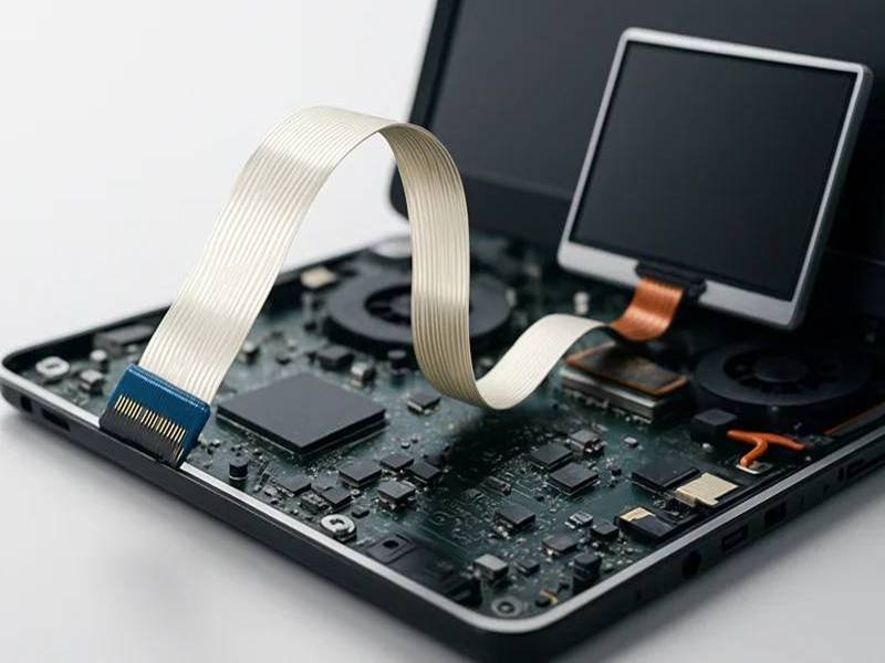
Open a laptop screen, printer, medical monitor, industrial control panel, camera module, or automotive display, and you will often find a thin flat cable hidden inside. This cable may look simple, but it solves one of the hardest problems in modern electronic design: how to connect multiple circuits in a narrow space without using a bulky wire harness.
FFC, or Flexible Flat Cable, is a thin flat cable made with parallel conductors laminated between insulation films. It is widely used to connect PCBs, displays, touch panels, sensors, cameras, printers, medical devices, and compact electronic modules. FFC cables save space, reduce weight, simplify assembly, and help product designers route signals through tight mechanical structures.
The real challenge is not understanding what FFC means. The real challenge is choosing the correct FFC for the device. Pitch, pin count, conductor thickness, contact direction, reinforcement length, material, shielding, bending requirement, and connector matching can all affect whether the cable works properly. Many sourcing mistakes happen because the cable “looks similar” but the pitch, contact side, or thickness is wrong.
That is why engineers and purchasing teams often send Sino-Conn product photos, samples, or connector models and ask: “Can you make the same FFC cable?” The answer usually starts with careful measurement, drawing confirmation, and specification checking before production begins.
What Is an FFC Cable?
An FFC cable is a Flexible Flat Cable designed to transmit signals, data, or low-to-medium power between electronic components in a compact space. It consists of multiple flat copper conductors arranged in parallel and laminated between thin insulating films.

FFC cables are commonly used where traditional round cables are too bulky or difficult to route. Because of their flat profile, consistent conductor spacing, and lightweight construction, FFC cables have become a standard interconnect solution in modern electronics.
Today, FFC cables can be found inside:
- LCD displays
- Touchscreen systems
- Laptops
- Printers
- Medical monitors
- Industrial control panels
- Automotive displays
- Cameras
- Embedded systems
- POS terminals
- Home appliances
As electronic products continue becoming thinner and more integrated, the demand for FFC cables continues to grow.
Many engineers consider FFC not simply as a cable, but as a mechanical design tool. In many products, the choice of FFC directly affects enclosure size, assembly efficiency, thermal design, and manufacturing cost.
FFC Meaning
FFC stands for Flexible Flat Cable.
The name accurately describes the cable structure.
Flexible means the cable can bend during installation and routing.
Flat means the conductors are arranged side-by-side in a ribbon-like structure.
Cable means it provides an electrical path between two electronic assemblies.
Unlike traditional wire harnesses, FFC cables do not use individually insulated round wires.
The comparison below helps illustrate the difference.
| Feature | FFC Cable | Traditional Wire Harness |
|---|---|---|
| Structure | Flat parallel conductors | Multiple round wires |
| Thickness | Extremely thin | Relatively thick |
| Weight | Very light | Heavier |
| Routing Space | Minimal | Larger |
| Assembly Speed | Fast | Moderate |
| Appearance | Organized and clean | Bulkier |
| Automation Compatibility | Excellent | Moderate |
This difference becomes increasingly important in modern electronics.
For example, a modern laptop display may have less than 3 mm of available cable routing space.
A traditional harness simply cannot fit.
An FFC cable allows manufacturers to route 20, 30, or even 50 circuits through an extremely narrow area while maintaining reliable performance.
Many customers contact Sino-Conn with only a photo of an existing cable and ask whether the same product can be manufactured.
The challenge is that two FFC cables can look identical while having completely different specifications.
Factors such as pitch, contact direction, conductor thickness, reinforcement size, and connector compatibility must all be verified before production.
FFC Construction
Although an FFC cable appears simple, its design is the result of carefully balancing flexibility, durability, electrical performance, and manufacturing efficiency.
A standard FFC cable consists of several layers.
| Component | Function |
|---|---|
| Copper Conductors | Carry signals or power |
| Insulation Film | Prevent short circuits |
| Adhesive Layer | Bonds cable structure |
| Reinforcement Layer | Improves connector insertion stability |
| Exposed Contact Area | Interfaces with connectors |
| Optional Shield Layer | Improves EMI performance |
The conductors are usually manufactured from high-conductivity copper.
Depending on application requirements, conductor thickness may vary.
Common conductor thickness options include:
| Copper Thickness | Typical Use |
|---|---|
| 18 μm | Compact electronics |
| 35 μm | General-purpose applications |
| 50 μm | Higher current designs |
| 70 μm | Specialized power applications |
Increasing conductor thickness improves current-carrying capability but reduces flexibility.
This creates a trade-off that engineers must consider.
For example:
A touchscreen display cable may prioritize flexibility.
A power distribution cable may prioritize current capacity.
A medical monitoring device may require both.
Material selection also plays a major role.
Most FFC cables use PET insulation film because it provides an excellent balance between cost and performance.
For more demanding environments, PI (Polyimide) materials may be selected.
| Material | Temperature Range | Common Applications |
|---|---|---|
| PET | Up to approximately 80–105°C | Consumer electronics |
| PI | Up to approximately 200°C | Industrial and automotive systems |
Customers often focus on cable length and pin count during sourcing.
However, experienced engineers usually pay more attention to:
- Pitch
- Conductor thickness
- Contact style
- Reinforcement dimensions
- Temperature rating
- Connector compatibility
These factors ultimately determine whether the cable will function correctly inside the product.

FFC Applications
FFC cables are used in almost every industry that requires compact electronic packaging.
The reason is straightforward.
Modern devices continue shrinking while adding more functionality.
As PCB density increases and available space decreases, FFC cables provide a practical solution.
The table below highlights common applications.
| Industry | Common FFC Application |
|---|---|
| Consumer Electronics | LCD displays, cameras, laptops |
| Medical Equipment | Patient monitors, diagnostic displays |
| Industrial Automation | HMI panels, control systems |
| Automotive Electronics | Instrument clusters, infotainment |
| Office Equipment | Printers, scanners |
| Retail Equipment | POS terminals |
| Security Systems | Cameras, access control devices |
| Embedded Systems | SBCs, display interfaces |
Medical equipment provides a good example of why FFC cables are valuable.
Many medical displays require:
- High reliability
- Compact installation
- Clean cable routing
- Stable signal transmission
A bulky wire harness may create unnecessary space constraints inside the enclosure.
An FFC cable allows designers to route multiple signal paths through a very small area while maintaining a clean internal layout.
At Sino-Conn, custom FFC projects for medical devices, industrial displays, and embedded systems are common.
Some customers provide complete engineering drawings.
Others provide only a photo or an old sample.
In both situations, engineering review is often necessary to verify:
- Pitch size
- Pin count
- Contact orientation
- Connector compatibility
- Mechanical dimensions
One industrial display customer approached Sino-Conn after experiencing sourcing issues with an obsolete FFC cable.
The original supplier had discontinued the part, and no technical documentation was available.
Using only the sample cable and connector information, the engineering team measured the pitch, conductor count, contact direction, and reinforcement dimensions. A replacement drawing was prepared and approved before sampling.
The customer was able to continue production without redesigning the display module.
This situation is more common than many people realize.
In the FFC industry, successful sourcing often depends as much on engineering support as it does on manufacturing capability.
That is why understanding the complete FFC structure—not just its appearance—is the first step toward selecting the right cable for a product.
Which FFC Types Are Most Common?
Not all FFC cables are the same. In fact, two FFC cables may appear almost identical to the naked eye but be completely incompatible with each other.
This is one of the most common reasons why engineers, purchasing teams, and maintenance departments encounter sourcing problems. A cable may have the same length and the same number of circuits, but if the pitch, contact orientation, thickness, reinforcement structure, or conductor specification differs, the cable may not fit the connector or function properly.
When customers contact Sino-Conn for replacement FFC cables, many initially provide only a photo or an old sample. The first step is usually not pricing. The first step is identifying exactly which type of FFC cable is being used.
The most common FFC classifications are based on:
- Pitch
- Contact orientation
- Conductor count
- Insulation material
- Shielding structure
- Reinforcement design
- Conductor thickness
Understanding these differences can prevent costly sourcing mistakes and help engineers choose a cable that matches both electrical and mechanical requirements.
FFC Pitch Options
Pitch is the distance from the center of one conductor to the center of the next conductor.
Among all FFC specifications, pitch is usually the most important because it determines whether the cable can physically mate with the connector.
Even a small difference can make the cable unusable.
The most common FFC pitch sizes used in today’s electronics are:
| Pitch | Typical Industries | Common Applications |
|---|---|---|
| 0.30 mm | Consumer Electronics | Cameras, smartphones |
| 0.50 mm | Display Systems | Laptops, LCD modules |
| 0.80 mm | Embedded Systems | Industrial displays |
| 1.00 mm | Industrial Equipment | HMI panels, controllers |
| 1.25 mm | Power Applications | Larger signal and power circuits |
| 2.54 mm | Specialized Equipment | Legacy systems |
In actual projects, 0.5 mm and 1.0 mm pitch account for a significant percentage of FFC demand.
Each pitch size offers different advantages.
| Smaller Pitch | Larger Pitch |
|---|---|
| Saves space | Easier handling |
| Higher circuit density | Better mechanical tolerance |
| Narrower cable width | Easier connector alignment |
| More compact devices | Better for industrial environments |
For example, a 40-pin cable using 0.5 mm pitch has a conductor width of approximately 20 mm.
The same 40-pin cable using 1.0 mm pitch would require approximately 40 mm of width.
In a laptop display, that size difference can determine whether the product can be manufactured at all.
One customer developing an embedded touchscreen system requested a replacement cable based solely on length and pin count.
After measuring the sample, the pitch was found to be 0.8 mm rather than the assumed 1.0 mm.
Had production started immediately, the cable would not have fit the connector and the entire batch would have been unusable.
This is why pitch verification is always one of the first steps in custom FFC projects at Sino-Conn.
FFC Contact Types
Contact orientation is another specification that creates frequent confusion.
Many customers focus on length, pitch, and pin count but overlook contact direction.
However, contact orientation directly determines whether the cable can connect correctly.
The two most common configurations are:
| Contact Type | Description |
|---|---|
| Type A | Contacts on the same side |
| Type D | Contacts on opposite sides |
Visually, the difference appears small.
Functionally, the difference is critical.
A Type A cable inserted into a design requiring Type D may not make electrical contact at all.
The selection depends on connector placement.
For example:
- PCB connectors facing the same direction often use one contact style.
- PCB connectors facing opposite directions often require the other.
The following issues frequently occur when contact orientation is not verified:
- No electrical connection
- Improper insertion
- Twisted cable routing
- Mechanical stress during assembly
- Increased risk of cable damage
One industrial automation customer experienced intermittent communication failures after replacing an FFC cable sourced from a local distributor.
The cable had the correct pitch and conductor count but used the opposite contact orientation.
The connector appeared to lock properly, but several conductors failed to make consistent contact.
After reviewing the assembly, the issue was resolved by supplying the correct contact configuration.
For this reason, Sino-Conn includes contact orientation details in all custom drawing approvals before production begins.
FFC Material Options
The material used in an FFC cable affects much more than appearance.
It influences:
- Flexibility
- Operating temperature
- Service life
- Chemical resistance
- Mechanical durability
- Cost
The most common insulation materials are PET and PI.
| Material | Operating Temperature | Typical Use |
|---|---|---|
| PET | Approximately 80°C–105°C | Consumer electronics |
| PI (Polyimide) | Up to approximately 200°C | Industrial, automotive, medical |
| Reinforced PET | Enhanced durability | Equipment with repeated assembly |
PET remains the most widely used material because it offers excellent value and good electrical insulation.
PI becomes more attractive when products operate in demanding environments.
Examples include:
- Industrial control systems
- Automotive electronics
- Medical equipment
- High-temperature applications
Material selection often depends on operating conditions rather than industry alone.
Questions engineers typically consider include:
- What temperature will the cable experience?
- Will the cable move repeatedly?
- Is the environment humid?
- Are cleaning chemicals involved?
- Does the product require a long service life?
For instance, a medical display used in a hospital may undergo daily cleaning and continuous operation.
A consumer tablet may operate under far less demanding conditions.
Although both products may use FFC cables, the material priorities can be very different.
At Sino-Conn, customers frequently request guidance when replacing obsolete FFC cables because the original material specifications are unavailable. Reviewing the application environment often helps identify the most suitable replacement.
FFC Shielded vs Unshielded
Most standard FFC cables are unshielded.
For many display and control applications, this is perfectly adequate.
However, as electronic systems become faster and more densely packed, EMI considerations become increasingly important.
Shielding can help reduce interference caused by:
- Motors
- Power supplies
- Wireless modules
- RF systems
- High-speed data signals
The two primary categories are:
| Type | Characteristics |
|---|---|
| Unshielded FFC | Lower cost, thinner structure |
| Shielded FFC | Improved EMI protection |
The decision depends on the application.
Unshielded FFC is commonly used in:
- LCD displays
- Consumer electronics
- Printers
- Embedded control panels
Shielded FFC is more commonly used in:
- Medical equipment
- Industrial automation
- Automotive electronics
- High-speed display systems
- Sensitive sensor applications
Many engineers assume shielding is simply an extra layer added to the cable.
In practice, successful shielding requires consideration of:
- Shield material
- Grounding method
- Connector compatibility
- Cable thickness
- Installation environment
A poorly implemented shield may add cost without improving performance.
One industrial customer operating equipment near servo drives experienced unstable display signals.
The original unshielded cable worked correctly in laboratory conditions but encountered interference during field operation.
After reviewing the environment, a shielded FFC design was implemented and the signal stability improved significantly.
This illustrates an important principle:
Shielding should be driven by actual electrical conditions rather than assumptions.
FFC Conductor Count and Reinforcement Options
Beyond pitch and materials, conductor count is another major differentiator.
Common conductor counts include:
| Conductor Count | Typical Applications |
|---|---|
| 4–10 Pin | Sensors, small modules |
| 12–20 Pin | Displays, touch panels |
| 24–40 Pin | Embedded systems |
| 50–80 Pin | High-density electronics |
| 100+ Pin | Specialized equipment |
Higher conductor counts allow more signals to be transmitted through a compact cable.
However, increasing conductor count may also increase:
- Cable width
- Complexity
- Cost
- Connector requirements
Reinforcement design is equally important.
Most FFC cables include stiffeners at the contact area.
These stiffeners help:
- Improve insertion stability
- Maintain contact pressure
- Prevent cable damage
- Support repeated mating cycles
Common stiffener materials include:
- PET
- PI
- FR materials
Improper stiffener thickness is a surprisingly common cause of connection problems.
A cable may have the correct pitch and conductor count, yet still fail because the reinforcement thickness does not match the connector specification.
This is why Sino-Conn carefully reviews:
- Pitch
- Contact orientation
- Reinforcement dimensions
- Connector compatibility
- Material selection
before finalizing custom FFC drawings.
For engineers and purchasing teams, understanding these FFC variations is essential. Selecting the correct type at the beginning of a project can prevent redesigns, production delays, and unnecessary costs later in development.
Why Use FFC Cables?
FFC cables have been used in electronics for decades, but their importance has increased dramatically as products continue to become smaller, thinner, lighter, and more powerful.
A modern laptop contains more functionality than an industrial computer from twenty years ago, yet occupies only a fraction of the space. Medical devices are becoming more portable. Industrial control systems are becoming more compact. Automotive displays are becoming larger while dashboard space becomes more limited.
All of these trends create the same challenge:
How do you connect multiple electronic components inside a limited space without increasing product size, weight, assembly complexity, or manufacturing cost?
This is where FFC cables provide significant advantages.
An FFC cable is not simply a replacement for a wire harness. In many products, it allows engineers to build designs that would be difficult or impossible with traditional cable assemblies.
The decision to use FFC is usually driven by a combination of:
- Space limitations
- Product weight targets
- Assembly efficiency
- Manufacturing cost
- Electrical performance
- Product appearance
- Long-term reliability
The following sections explain why FFC has become one of the most widely used interconnect solutions across consumer electronics, industrial equipment, medical devices, automotive systems, and embedded electronics.
FFC and Space Saving
Space is often the first reason engineers choose FFC.
In many electronic products, internal space is more valuable than the cost of the cable itself.
For example:
A laptop display assembly may provide only a few millimeters of clearance between the LCD module and the rear cover.
A medical monitor may contain multiple PCBs, power supplies, displays, cooling systems, and communication modules inside a compact enclosure.
An automotive display may require dozens of signal connections while fitting inside a tightly packaged dashboard.
Traditional wire harnesses consume significant space because each conductor requires:
- Individual insulation
- Air space between wires
- Bundle routing clearance
- Additional fastening structures
FFC eliminates much of this wasted volume.
The comparison below illustrates the difference.
| Cable Type | Typical Thickness |
|---|---|
| Standard Wire Harness | 5–15 mm |
| Ribbon Cable | 1–5 mm |
| FFC Cable | 0.10–0.50 mm |
The difference becomes even more obvious when conductor count increases.
For example:
| Connection Requirement | Wire Harness Width | FFC Width |
|---|---|---|
| 20 Circuits | Large bundle | Approximately 10 mm |
| 40 Circuits | Very bulky | Approximately 20 mm |
| 60 Circuits | Difficult routing | Approximately 30 mm |
In products where every millimeter matters, this reduction can significantly influence overall design.
One industrial display customer approached Sino-Conn because their existing wire harness interfered with enclosure assembly. The original design required technicians to manually route the harness around several components before final assembly.
After converting the design to an FFC solution, cable routing became significantly simpler, assembly time decreased, and the enclosure could be assembled more consistently.
The cable itself did not change the device function.
It changed how efficiently the product could be manufactured.
FFC and Flexibility
The word “flexible” is part of the FFC name, but flexibility means much more than simply bending.
For engineers, flexibility affects:
- Product design freedom
- Assembly convenience
- Connector reliability
- Long-term durability
A highly flexible cable can follow complex routing paths without placing excessive force on connectors or PCB solder joints.
This becomes particularly important in products with:
- Hinged displays
- Folding mechanisms
- Sliding components
- Serviceable panels
- Moving modules
The flexibility of an FFC cable depends on several factors.
| Design Element | Influence |
|---|---|
| Copper Thickness | Thinner copper improves flexibility |
| Cable Width | Narrower cables bend more easily |
| Material Type | PET and PI behave differently |
| Shield Structure | Shielding may reduce flexibility |
| Reinforcement Length | Affects bending near connectors |
Not every application requires maximum flexibility.
For example:
A fixed display connection may only bend once during installation.
A printer cable may bend thousands of times during product life.
An automotive display cable may experience continuous vibration.
A medical device cable may require both flexibility and durability.
This is why FFC selection should always consider actual operating conditions.
One customer manufacturing portable diagnostic equipment initially selected an FFC based on dimensions alone.
After prototype testing, engineers discovered that the cable routing required repeated movement during device opening and closing.
A revised cable structure was recommended that improved flex performance without increasing overall dimensions.
Small design changes often produce significant improvements in reliability.
FFC and Fast Assembly
Assembly cost is a major factor in electronic manufacturing.
When a factory produces thousands or tens of thousands of units per month, reducing assembly time by only a few seconds per unit can create substantial savings.
FFC cables simplify assembly because they are highly standardized.
Instead of routing individual wires, operators simply insert the cable into the connector and lock the mechanism.
The difference becomes clear when comparing assembly processes.
| Process Step | Wire Harness | FFC |
|---|---|---|
| Individual Wire Management | Required | Not Required |
| Routing Complexity | Higher | Lower |
| Installation Time | Longer | Shorter |
| Visual Verification | More Difficult | Easier |
| Repeatability | Moderate | Excellent |
Many electronics manufacturers value FFC because it reduces opportunities for human error.
The conductors remain fixed in position.
The spacing remains consistent.
The cable follows the same routing path every time.
This helps improve production consistency.
One touchscreen equipment manufacturer compared two assembly methods during pilot production.
The FFC design reduced installation time by approximately 25% compared with the original wire harness solution.
While the exact savings depend on the application, the trend is consistent across many industries.
Simpler assembly often translates into:
- Lower labor costs
- Faster production
- Better consistency
- Fewer assembly errors
For OEM manufacturers producing large volumes, these benefits can be just as important as the cable cost itself.
FFC and Cost Control
Many people assume FFC is selected because it is the cheapest option.
That is not always true.
The cost of an FFC cable should be evaluated within the context of the entire product.
A cable that costs slightly more may reduce expenses elsewhere.
Examples include:
- Faster assembly
- Smaller enclosure size
- Reduced labor
- Lower shipping weight
- Improved reliability
- Simplified inventory management
The comparison below helps illustrate this concept.
| Cost Factor | Wire Harness | FFC |
|---|---|---|
| Cable Cost | Often Lower | Moderate |
| Assembly Labor | Higher | Lower |
| Product Size Impact | Larger | Smaller |
| Routing Complexity | Higher | Lower |
| Manufacturing Efficiency | Moderate | High |
| Automation Compatibility | Moderate | Excellent |
This is why many engineering teams evaluate total project cost rather than focusing solely on cable pricing.
Consider a display system that uses a traditional harness.
If switching to FFC allows the enclosure to be reduced by even a few millimeters, material savings across the entire product may exceed the difference in cable cost.
A customer developing a compact industrial controller experienced exactly this situation.
The original wire harness solution was slightly cheaper.
However, the FFC design reduced assembly time, simplified cable routing, and allowed the enclosure size to be reduced.
The overall product cost decreased even though the cable itself cost more.
At Sino-Conn, these discussions occur regularly during project reviews.
Some customers prioritize the lowest possible unit cost.
Others focus on assembly efficiency, space optimization, or product reliability.
The best solution depends on the product’s design goals.
For this reason, successful FFC selection rarely comes down to cable price alone.
The real question is:
Which solution creates the best balance between performance, manufacturability, reliability, and total product cost?
In many modern electronic products, the answer is often an FFC cable.
How Do You Choose an FFC?
Choosing an FFC cable starts with one simple rule: do not choose by appearance alone.
Many FFC cables look almost the same in photos. They may have the same color, similar length, and the same number of visible conductors. But small differences in pitch, contact direction, cable thickness, conductor size, stiffener design, or material can decide whether the cable fits correctly or fails during assembly.
For engineers, the right FFC must match the electrical design, connector system, mechanical space, and working environment.
For purchasing teams, the right FFC must also match cost target, lead time, documentation needs, and future production stability.
A complete FFC selection usually checks these points:
| Selection Item | What to Confirm | Why It Matters |
|---|---|---|
| Pitch | 0.3 mm, 0.5 mm, 1.0 mm, etc. | Must match connector |
| Pin Count | Number of conductors | Must match circuit requirement |
| Length | Overall cable length | Affects routing and assembly |
| Contact Type | Same side or opposite side | Must match connector direction |
| Cable Thickness | Total thickness at contact area | Must fit connector lock |
| Stiffener Size | Length and thickness | Affects insertion stability |
| Conductor Thickness | Copper thickness and width | Affects current and flexibility |
| Material | PET, PI, reinforced material | Affects temperature and durability |
| Shielding | Shielded or unshielded | Affects EMI performance |
| Compliance | RoHS, REACH, PFAS, UL, COC | Supports customer approval |
If even one of these items is wrong, the cable may not work.
A common sourcing mistake is sending a supplier a picture and saying, “Please quote this FFC.” A photo can help, but it cannot reliably show pitch, conductor thickness, or contact-side structure. For accurate quotation and production, a drawing, sample, connector model, or detailed specification is much safer.
At Sino-Conn, many custom FFC projects begin with incomplete information. Customers may only have a sample, photo, or device model. In these cases, our team helps check key dimensions, prepare drawings, and confirm specifications before sampling. This reduces the risk of producing a cable that looks right but cannot be used.
FFC Length Selection
FFC length is one of the first specifications customers provide, but it is also one of the easiest to underestimate.
Many people measure only the straight-line distance between two connectors. In real product design, the cable usually needs to follow a routing path. It may need to bend around plastic ribs, pass under a PCB, go through a hinge, or leave room for assembly handling.
A cable that is 10 mm too short can create connector stress.
A cable that is 30 mm too long can create folding problems, interfere with nearby parts, or increase signal exposure.
Length selection should consider:
- Connector-to-connector distance
- Actual cable routing path
- Required bending radius
- Assembly tolerance
- Movement allowance
- Service or repair access
- Final enclosure space
Different applications require different length strategies.
| Application | Length Strategy | Reason |
|---|---|---|
| Fixed PCB-to-PCB Link | Use the shortest safe length | Reduces clutter and signal exposure |
| LCD Display Connection | Add routing margin | Prevents cable tension during assembly |
| Hinged Cover | Include movement allowance | Prevents fatigue during opening and closing |
| Sliding Module | Match full travel distance | Avoids pulling during movement |
| Serviceable Equipment | Leave maintenance slack | Allows disassembly without damage |
For fixed internal connections, shorter is often better. It keeps the internal structure clean and reduces unnecessary cable movement.
For moving parts, shorter is not always safer. The cable needs enough length to move without sharp bending or pulling at the connector.
A practical example involved a compact industrial display. The customer first requested an FFC length based on the straight-line distance between the display connector and PCB connector. During assembly review, the cable had to pass around a plastic support column, which added extra routing distance. If the original length had been used, the cable would have been under constant tension after assembly. The final design added a small length margin and improved reliability without changing the enclosure design.
At Sino-Conn, when customers are unsure about length, we recommend sending the internal layout drawing, installation photo, or sample cable. In many cases, reviewing the real routing path helps avoid trial-and-error sampling.
FFC Pitch Selection
Pitch is the center-to-center distance between adjacent conductors. It is one of the most critical FFC specifications because it must match the connector exactly.
If the pitch is wrong, the cable cannot mate with the connector correctly.
Common FFC pitch sizes include:
| FFC Pitch | Common Use | Main Advantage |
|---|---|---|
| 0.30 mm | Small camera modules, compact devices | Maximum space saving |
| 0.50 mm | LCD displays, laptops, touch panels | High circuit density |
| 0.80 mm | Embedded systems, display boards | Balance of size and handling |
| 1.00 mm | Industrial equipment, medical devices | Easier assembly |
| 1.25 mm | Larger signal or low-power lines | Stronger mechanical tolerance |
| 2.54 mm | Legacy or special designs | Easier manual handling |
Smaller pitch makes the cable narrower, but it also increases the need for accurate assembly and connector matching.
For example:
| Pin Count | 0.5 mm Pitch Approx. Width | 1.0 mm Pitch Approx. Width |
|---|---|---|
| 20 Pin | About 10 mm | About 20 mm |
| 30 Pin | About 15 mm | About 30 mm |
| 40 Pin | About 20 mm | About 40 mm |
| 50 Pin | About 25 mm | About 50 mm |
The space difference is huge. In a laptop, 0.5 mm pitch may be necessary. In an industrial controller, 1.0 mm may be easier to assemble and more reliable during maintenance.
Pitch cannot be judged accurately from a normal photo. A close-up image with a ruler can help, but the safest methods are:
- Check the connector model
- Measure the existing sample
- Review the PCB drawing
- Confirm the original cable specification
- Send the sample to the supplier for measurement
One customer asked Sino-Conn to quote a 30-pin FFC based on a photo. The customer assumed it was 1.0 mm pitch because the cable looked wide. After checking the connector model, it was actually 0.8 mm pitch. That small difference would have made the cable unusable if not confirmed before production.
This is why pitch confirmation should happen before quotation, not after sampling.
FFC Current Rating
FFC cables are often used for signals, but they can also carry power in many devices.
Current rating depends on conductor width, copper thickness, temperature rise, cable length, and how many conductors carry current at the same time.
A cable used only for low-speed signals may use thinner conductors.
A cable carrying display backlight power, motor control signals, or internal device power may need thicker copper or wider conductor design.
Key factors that affect FFC current capacity include:
| Factor | Effect |
|---|---|
| Copper Thickness | Thicker copper supports more current |
| Conductor Width | Wider conductor reduces resistance |
| Cable Length | Longer cable increases resistance |
| Ambient Temperature | Higher temperature reduces safety margin |
| Number of Power Lines | More parallel lines can share current |
| Heat Dissipation | Limited airflow increases temperature rise |
Common copper thickness options include:
| Copper Thickness | Suitable Use |
|---|---|
| 18 μm | Low-current signal transmission |
| 35 μm | General signal and light power |
| 50 μm | Higher current or longer cable |
| 70 μm | Special power-oriented designs |
A simple way to reduce current stress is to assign multiple conductors to the same power or ground path. This is common in display modules and embedded systems.
For example, instead of using one conductor for 1A current, a design may use two or three conductors in parallel to reduce resistance and temperature rise.
Engineers should confirm:
- Maximum operating current
- Peak current
- Voltage level
- Signal type
- Duty cycle
- Allowed temperature rise
- Working environment temperature
A common mistake is assuming that “same pin count” means the cable can carry the same load. If one FFC uses 35 μm copper and another uses 18 μm copper, their electrical performance can be very different.
At Sino-Conn, when customers request custom FFC for power-related applications, we normally ask about voltage, current, conductor count, and working environment. This helps avoid under-designed cables that may heat up or fail prematurely.
FFC Connector Matching
Connector matching is where many FFC sourcing mistakes happen.
An FFC must match the connector in several details, not just pitch and pin count.
Important connector-matching items include:
| Matching Item | Why It Matters |
|---|---|
| Pitch | Must align with connector contacts |
| Pin Count | Must match circuit quantity |
| Contact Direction | Must face connector terminals |
| Contact Length | Must reach correct contact area |
| Total Thickness | Must fit connector locking structure |
| Stiffener Thickness | Affects insertion and contact pressure |
| Cable Width | Must fit connector opening |
| Insertion Depth | Affects electrical connection |
Many FFC connectors use a ZIF or non-ZIF structure.
ZIF means Zero Insertion Force. The connector latch opens, the cable is inserted, and then the latch closes to hold the cable.
Non-ZIF connectors require more insertion force and depend heavily on cable end thickness and stiffness.
If the stiffener is too thin, contact pressure may be weak.
If it is too thick, the cable may not insert correctly or the latch may not close.
Contact direction is another major issue.
| Contact Style | Description |
|---|---|
| Same-Side Contacts | Exposed contacts face the same side at both ends |
| Opposite-Side Contacts | Exposed contacts face opposite sides |
A cable can have the correct pitch, length, and pin count but still fail if the contact direction is wrong.
This is especially common when customers reorder from photos or old samples without a drawing.
For this reason, Sino-Conn provides drawings for custom FFC projects before production. The drawing normally shows cable length, pitch, pin count, exposed contact side, reinforcement length, contact length, and key dimensions. Customers can review and approve the file before sampling or mass production.
FFC Performance Verification
A good FFC selection process should end with verification.
Before moving from sample to production, engineers should check both electrical and mechanical performance.
Basic verification items include:
| Check Item | Purpose |
|---|---|
| Continuity Test | Confirms every conductor is connected |
| Short Circuit Test | Ensures conductors are isolated |
| Dimension Check | Confirms length, width, and pitch |
| Contact Inspection | Confirms exposed copper quality |
| Connector Fit Test | Confirms insertion and locking |
| Function Test | Confirms performance inside device |
| Bend Check | Confirms routing safety |
For medical, industrial, automotive, or high-reliability products, additional testing may be needed:
- Temperature test
- Humidity test
- Flex test
- Vibration test
- EMI check
- Impedance test
- Pull test
- Aging test
Not every project needs every test. The correct test plan depends on the application.
A consumer display cable may only need standard electrical and dimensional testing.
An industrial control cable used near motors may need EMI evaluation.
A medical device cable may need additional documentation and reliability verification.
At Sino-Conn, FFC products are checked through multiple quality steps, including process inspection, finished product inspection, and pre-shipment inspection. For custom projects, production is based on the approved drawing to reduce variation between samples and bulk orders.
Choosing the right FFC is not difficult when the correct information is available. The key is to confirm the hidden details before production starts. Pitch, contact side, thickness, conductor structure, material, and connector compatibility matter just as much as length and pin count.
A safe approach is to provide one of the following when requesting a quote:
- Drawing
- Connector model
- Existing sample
- Close-up product photo
- PCB connector information
- Electrical requirement
- Application description
With these details, Sino-Conn can help identify the correct FFC structure, prepare drawings, recommend materials, and provide samples for testing before volume production.

How Can FFC Be Customized?
One of the biggest misconceptions about FFC cables is that they are standard off-the-shelf products with limited customization options.
In reality, a large percentage of FFC cables used in medical devices, industrial equipment, automotive displays, embedded systems, commercial electronics, and OEM products are custom-designed around a specific application.
The reason is simple.
FFC cables sit at the intersection of electrical design and mechanical design.
A PCB layout may determine the pin count.
The enclosure design may determine the cable length.
The connector system may determine the pitch.
The operating environment may determine the material.
The signal type may determine whether shielding is required.
As a result, two products performing similar functions may use completely different FFC designs.
At Sino-Conn, many FFC projects begin with:
- An existing sample
- A product photo
- A discontinued part number
- A connector model
- A hand sketch
- A PCB drawing
- An engineering concept
In many cases, customers do not have a complete FFC specification.
The engineering team helps convert the available information into a manufacturable design and approved drawing before production begins.
The most commonly customized areas include:
| Customization Area | Typical Modification |
|---|---|
| Length | 30 mm to 3000 mm+ |
| Pitch | 0.3 mm to 2.54 mm |
| Pin Count | 4 to 100+ circuits |
| Contact Direction | Same-side or opposite-side |
| Conductor Thickness | 18 μm to 70 μm+ |
| Material | PET, PI, reinforced structures |
| Shielding | Standard or EMI-protected |
| Stiffener | Custom thickness and length |
| Pinout | Custom conductor assignments |
| Connector Integration | Complete cable assembly |
The flexibility of FFC customization is one reason it remains popular across so many industries.
Custom FFC Length
Length is the most frequently customized FFC specification.
Many people assume selecting cable length is simple.
In practice, length directly affects:
- Installation
- Routing
- Reliability
- Manufacturing efficiency
- Serviceability
A cable that is too short can place constant stress on connectors.
A cable that is too long can create routing problems and occupy valuable internal space.
Most successful projects begin by analyzing the actual cable path rather than simply measuring the distance between two connectors.
The difference can be significant.
| Measurement Method | Result |
|---|---|
| Straight-Line Distance | Often Too Short |
| Actual Routing Path | More Accurate |
| Routing + Assembly Margin | Preferred |
For example, a cable connecting an LCD module to a PCB may need to:
- Route around plastic supports
- Pass beneath a shielding plate
- Fold around structural features
- Allow assembly movement
A straight-line measurement of 120 mm may become a required cable length of 150 mm or more.
One industrial control customer originally specified a 100 mm cable based on connector spacing.
After reviewing installation photos, the actual routing path required approximately 135 mm.
Producing the original design would have created tension on the connector after assembly.
This issue was identified during the drawing review stage and corrected before samples were built.
At Sino-Conn, customers frequently provide:
- Housing drawings
- Assembly photos
- Existing samples
This information allows engineers to verify that the selected length works not only electrically but also mechanically.
Length customization can range from extremely short internal jumpers to multi-meter specialized FFC assemblies.
Custom FFC Pinout
Many standard FFC cables use a one-to-one conductor arrangement.
Pin 1 connects to Pin 1.
Pin 2 connects to Pin 2.
Pin 3 connects to Pin 3.
However, many OEM products require custom conductor assignments.
This is especially common when:
- Existing PCB designs must be retained
- Connector locations change
- Signal routing needs optimization
- Legacy systems require adaptation
Custom pinout design can eliminate the need for:
- Adapter boards
- Additional wiring
- PCB redesigns
- Secondary harnesses
Examples of custom pinout modifications include:
| Pinout Option | Purpose |
|---|---|
| Signal Crossing | Match connector orientation |
| Power Redistribution | Improve current handling |
| Ground Enhancement | Improve signal stability |
| Mixed Signal Routing | Separate power and data |
| Legacy Conversion | Maintain compatibility |
One customer developing a medical display system redesigned the controller PCB but wanted to continue using the existing display assembly.
Changing the display interface would have delayed the project and increased costs.
Instead, a custom FFC pinout was developed that matched the new PCB while maintaining compatibility with the display.
The modification allowed the project to proceed without changing either major component.
This approach is often faster and less expensive than redesigning electronic hardware.
For custom pinout projects, Sino-Conn provides drawings showing conductor assignments before production, allowing engineers to verify every circuit position.
Custom FFC Materials
Material selection has a direct impact on how the cable performs throughout the life of the product.
Two FFC cables may have identical dimensions yet perform very differently because of material differences.
The most commonly customized materials include:
| Material | Main Advantage |
|---|---|
| PET | Cost-effective |
| Reinforced PET | Better mechanical durability |
| PI (Polyimide) | Higher temperature capability |
| High-Flex Construction | Improved bending performance |
| Shielded Structure | Better EMI protection |
The right material depends on the application.
Questions often considered include:
- Will the cable move repeatedly?
- What temperature will it experience?
- Is the environment humid?
- Are cleaning chemicals present?
- Is long-term durability critical?
- Are EMI concerns present?
The following comparison illustrates how application requirements influence material selection.
| Application | Material Priority |
|---|---|
| Consumer Electronics | Cost and compact size |
| Industrial Equipment | Temperature resistance |
| Medical Devices | Reliability and cleanliness |
| Automotive Electronics | Durability and temperature performance |
| Portable Equipment | Flexibility |
One customer developing a handheld medical device initially selected a standard PET structure because it met the dimensional requirements.
After reviewing the application, it became clear the cable would experience frequent movement and regular cleaning.
A more robust material solution was recommended to improve durability without significantly increasing cost.
Material customization often delivers some of the largest improvements in product reliability.
Custom FFC Shielding
As electronic systems become more complex, EMI protection becomes increasingly important.
Many FFC cables operate perfectly without shielding.
Others require shielding to maintain stable performance.
Shielded FFC designs are commonly used in:
- Medical equipment
- Industrial automation
- Automotive displays
- High-speed displays
- Sensitive sensor systems
Shielding options may include:
| Shield Option | Benefit |
|---|---|
| Foil Shield | Basic EMI protection |
| Conductive Layer | Reduced interference |
| Grounded Shield | Improved signal integrity |
| Custom Shield Design | Application-specific protection |
The decision depends on factors such as:
- Signal speed
- Cable length
- Nearby power electronics
- RF environment
- Motor proximity
One industrial customer operating equipment near servo drives experienced intermittent display issues.
The original cable passed all basic functional tests.
However, field operation exposed the cable to significant electrical noise.
A custom shielded FFC solution improved signal stability without requiring PCB modifications.
This example highlights an important point:
Shielding should be selected based on operating conditions rather than assumptions.
Custom FFC Assemblies
Many projects require more than a standalone FFC cable.
Customers increasingly request complete assemblies that simplify procurement and production.
Common assembly options include:
| Assembly Feature | Benefit |
|---|---|
| Connector Integration | Simplifies installation |
| Pre-Assembled Cable Sets | Reduces assembly time |
| EMI Components | Improved performance |
| Labeling | Easier identification |
| Custom Reinforcement | Better mechanical fit |
| Protective Layers | Improved durability |
Instead of sourcing multiple components from different suppliers, many OEMs prefer receiving a ready-to-install assembly.
This approach can:
- Reduce purchasing complexity
- Improve production efficiency
- Reduce assembly errors
- Simplify inventory management
At Sino-Conn, many customers begin with a simple request such as:
“Can you make the same cable?”
After reviewing the project, the final solution often includes custom lengths, modified pinouts, improved materials, shielding enhancements, and connector integration.
The result is a cable assembly optimized for the actual application rather than a standard product adapted to fit.
That flexibility is one of the main reasons FFC technology continues to be widely used in modern electronics, medical equipment, industrial systems, and embedded devices.
Why Choose Sino-Conn FFC?
Finding an FFC supplier is easy.
Finding a supplier that can correctly identify an unknown FFC cable, prepare drawings, recommend improvements, support prototypes, maintain production consistency, and provide complete documentation is much more difficult.
Many FFC sourcing problems are not caused by manufacturing capability.
They happen much earlier.
For example:
- The pitch is identified incorrectly.
- The contact orientation is misunderstood.
- The stiffener thickness does not match the connector.
- The cable length is measured incorrectly.
- The replacement cable uses a different conductor thickness.
- The customer only has a sample and no drawing.
When these issues are not discovered before production, the result is often wasted time, additional sample rounds, delayed projects, and higher development costs.
This is why many engineers evaluate a supplier based on engineering support rather than production capacity alone.
At Sino-Conn, a large percentage of FFC projects are not standard catalog products. Most are custom designs developed around a customer’s specific device.
Customers typically come to us with:
- Existing samples
- Product photos
- Connector part numbers
- Mechanical drawings
- PCB layouts
- Engineering concepts
- Obsolete part numbers
Our role is not simply to manufacture the cable.
Our role is to help customers move from concept to working product as quickly and accurately as possible.
FFC Engineering Support
One of the biggest differences between a trading supplier and a technical supplier is engineering involvement.
Many FFC projects begin with incomplete information.
A customer may know:
- The cable length
- The pin count
- The product model
But may not know:
- Pitch
- Contact direction
- Copper thickness
- Stiffener specification
- Material type
- Connector compatibility
This situation is extremely common.
In fact, many OEM maintenance teams contact Sino-Conn because they are trying to replace a cable from equipment that was designed years ago.
The original supplier may no longer exist.
The documentation may be unavailable.
The only available information may be an old cable sample.
This is where engineering support becomes valuable.
Sino-Conn can assist with:
| Engineering Service | Customer Benefit |
|---|---|
| Sample Analysis | Identify unknown cable specifications |
| Connector Matching | Reduce compatibility risks |
| Pitch Verification | Prevent sourcing mistakes |
| Drawing Preparation | Faster engineering approval |
| Material Recommendations | Better reliability |
| Shielding Recommendations | Improved signal performance |
| Pinout Verification | Avoid wiring errors |
| Alternative Solutions | Reduce cost or lead time |
One industrial automation customer needed to replace a discontinued FFC cable used in a control panel.
The original documentation was unavailable.
Using the sample cable, connector photos, and PCB dimensions, the engineering team identified the pitch, conductor count, contact orientation, and stiffener structure.
A replacement drawing was prepared and approved before production.
The customer avoided redesigning the control board and continued production without interruption.
This type of project is common because many electronic products remain in service for years after the original supplier stops supporting them.
FFC Drawing Service
Drawings are one of the most overlooked parts of a successful FFC project.
Many sourcing problems occur because assumptions are made instead of specifications being confirmed.
For example:
A customer may request:
- 30 Pin
- 0.5 mm Pitch
- 200 mm Length
That information alone is not enough to manufacture a reliable replacement.
Important details still need verification.
These include:
- Contact direction
- Contact length
- Cable thickness
- Stiffener thickness
- Reinforcement length
- Material type
- Tolerance requirements
This is why Sino-Conn prepares drawings before production.
A proper FFC drawing helps both sides verify exactly the same product.
Typical drawing content includes:
| Drawing Information | Purpose |
|---|---|
| Overall Length | Dimensional verification |
| Pitch | Connector compatibility |
| Pin Count | Circuit verification |
| Contact Orientation | Mechanical compatibility |
| Stiffener Dimensions | Connector fit |
| Material Specification | Performance confirmation |
| Tolerance Information | Manufacturing control |
For most projects, drawings can be prepared within approximately three days.
For urgent projects where information is complete, drawings may be prepared significantly faster.
Many customers use these drawings internally for:
- Engineering approval
- Purchasing approval
- Production planning
- Supplier qualification
A drawing often prevents problems that would otherwise only be discovered after samples arrive.
FFC Quality Control
A custom FFC cable is only useful if every production batch remains consistent.
Even small variations can create assembly issues.
Examples include:
- Pitch deviation
- Incorrect conductor count
- Contact plating defects
- Stiffener thickness variation
- Cable length variation
- Contact orientation errors
This is why quality control plays a major role in FFC manufacturing.
At Sino-Conn, inspection takes place throughout production rather than only after assembly is completed.
The quality process generally includes:
| Inspection Stage | Purpose |
|---|---|
| Incoming Inspection | Verify raw materials |
| Process Inspection | Monitor production consistency |
| Finished Product Inspection | Verify functionality |
| Pre-Shipment Inspection | Confirm shipment quality |
Every custom project is produced according to the approved drawing.
Inspection commonly includes:
- Length verification
- Pitch verification
- Pin count verification
- Contact orientation verification
- Visual inspection
- Connector fit verification
- Continuity testing
For many industrial and medical customers, consistency is often more important than achieving the lowest possible unit price.
A slightly cheaper cable provides little value if it causes production interruptions later.
One embedded computing customer required multiple prototype batches over several months.
Because each batch was used for a different stage of product validation, dimensional consistency was critical.
Maintaining the same specifications throughout each build allowed testing to proceed without unexpected changes.
FFC Compliance Documents
Modern supply chains require much more than a physical cable.
Many customers must also provide documentation to engineering teams, quality departments, customers, and regulatory organizations.
Depending on the industry, documentation requirements may be extensive.
Common requests include:
| Document | Purpose |
|---|---|
| Specification Sheet | Technical review |
| Product Drawing | Design approval |
| RoHS Declaration | Environmental compliance |
| REACH Declaration | Chemical compliance |
| PFAS Declaration | Material transparency |
| COC | Certificate of Conformity |
| COO | Country of Origin |
| Material Information | Supplier qualification |
Medical, industrial, automotive, and commercial customers often require these documents before approving a new supplier.
At Sino-Conn, supporting documentation can be provided alongside the manufacturing process.
This helps customers complete:
- Internal reviews
- Supplier audits
- Product qualification
- Customer approval procedures
Faster documentation often means faster project approval.
FFC Rapid Samples
Product development schedules are becoming shorter every year.
Many engineering teams no longer have months available for prototype development.
A delayed cable can delay:
- Functional testing
- Mechanical verification
- Firmware development
- System integration
- Product certification
- Customer demonstrations
This is why sample lead time matters.
Sino-Conn supports both prototype and production programs.
Typical lead times include:
| Project Stage | Lead Time |
|---|---|
| Drawing Preparation | About 3 Days |
| Standard Samples | Approximately 2 Weeks |
| Urgent Samples | As Fast As 2–3 Days |
| Standard Production | Approximately 3–4 Weeks |
| Expedited Production | Around 2 Weeks |
Customers often use rapid samples for:
- Engineering validation
- Mechanical testing
- Functional testing
- Design verification
- Customer approval
One medical device startup needed custom FFC assemblies for a demonstration unit that would be presented to investors.
The project schedule was extremely tight.
By accelerating drawing review and sample production, testing was completed before the presentation date.
Fast response is not only about speed.
It helps customers keep development projects moving forward.
FFC Custom Manufacturing
Many FFC suppliers focus primarily on standard catalog products.
However, custom requirements are becoming increasingly common.
Customers often need modifications such as:
| Custom Requirement | Example |
|---|---|
| Length | 50 mm to several meters |
| Pin Count | 4–100+ circuits |
| Pitch | 0.3 mm to 2.54 mm |
| Material | PET, PI, reinforced structures |
| Shielding | EMI protection |
| Pinout | Custom conductor assignments |
| Contact Direction | Same-side or opposite-side |
| Assembly Features | Labels, connectors, reinforcement |
At Sino-Conn, custom projects represent a significant portion of production activity.
Many customers come with a challenge rather than a part number.
For example:
- An obsolete FFC that can no longer be purchased
- A product redesign requiring a new pinout
- A medical device requiring improved reliability
- An industrial controller requiring shielding
- An embedded system needing a custom length
In these situations, flexibility matters.
The ability to modify dimensions, materials, electrical definitions, and mechanical features allows customers to create solutions that fit their products rather than forcing their products to fit standard components.
For engineers, this often means fewer compromises.
For purchasing teams, it means more sourcing options.
For OEM manufacturers, it means faster development and smoother production.
These are the reasons many customers choose Sino-Conn not only as an FFC manufacturer, but as a long-term engineering and production partner for custom interconnect solutions.
Conclusion
FFC cables have become an essential part of modern electronics because they help designers save space, reduce weight, simplify assembly, and improve product integration.
From LCD displays and industrial control systems to medical devices, embedded computing platforms, automotive electronics, and consumer products, FFC technology continues to support increasingly compact designs.
The most successful FFC projects begin with a clear understanding of:
- Pitch
- Length
- Contact orientation
- Material
- Current requirements
- Connector compatibility
Choosing the correct specification early helps avoid redesigns, assembly issues, and unnecessary project delays.
If you are looking for a custom FFC cable, need help identifying an existing cable, want to optimize a design, or require engineering support for a new project, the Sino-Conn team can help.
Simply send a drawing, connector model, specification sheet, sample, or even a product photo. Our engineers can review the application, prepare drawings, recommend suitable materials, and provide prototype or production solutions tailored to your requirements.
Whether you need one prototype or high-volume production, Sino-Conn can support your FFC project from concept to delivery.