...

News & Article

Cable Assembly Insights. Built for Professionals.

Stay up to date with the latest in cable assembly engineering, connector compatibility, industry certifications, and real-world sourcing tips. Our blog is curated for engineers, R&D teams, and global buyers looking for practical insights and proven solutions.

Tutorials | Technical Specs | Market Trends | Application Use Cases

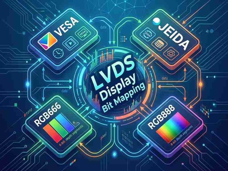
How Does LVDS Display Channel Mapping Work?

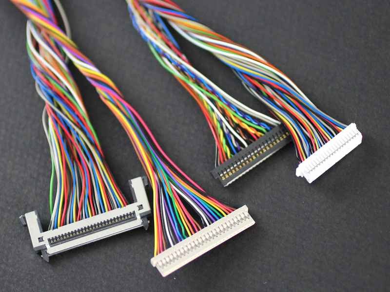
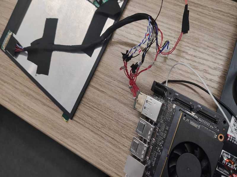
An LVDS display cable can look completely correct and still produce the wrong image. The connectors may mate cleanly, every conductor may pass continuity, and the panel may even light up, yet colors can be wrong, alternating columns can appear out of order, or the display can flicker only after the cable is installed inside the enclosure.
Read More »
Micro Coax Construction: How Is a Micro Coaxial Cable Built?

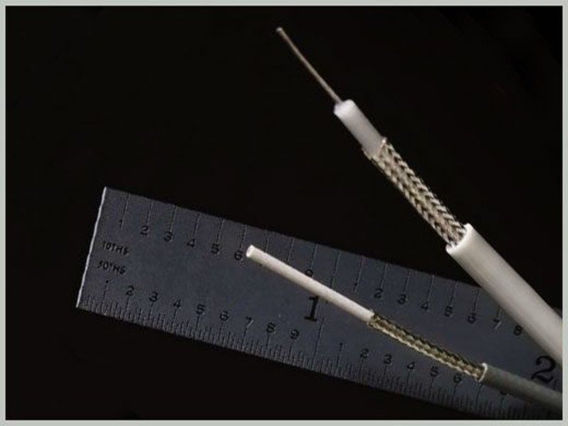
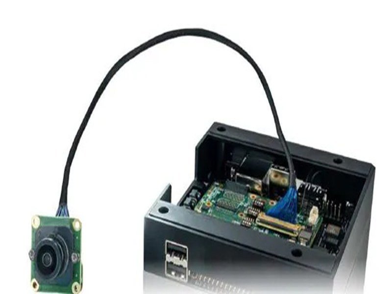
Micro coax looks simple until a product team tries to fit dozens of high-speed signal paths through a hinge, camera head, medical probe, display housing, or compact embedded device. The cable may be smaller than a millimeter in outside diameter, yet its center conductor, dielectric, shield, jacket, connector transition, and grounding path all have to work together.

Read More »
30-Pin vs 40-Pin eDP Display Connectors: What Is the Difference and Which One Is Compatible?

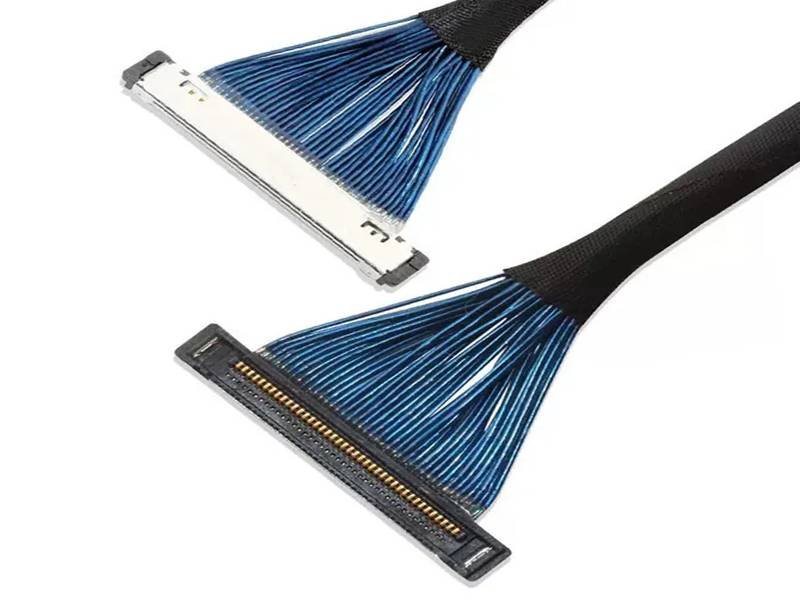
A display can look perfectly compatible on a specification sheet and still give you a black screen the moment it is connected. The panel may be the same size, use the same eDP interface, and even advertise the same resolution, yet one small assumption can derail the whole replacement or development project: treating 30-pin or 40-pin as a complete electrical specification. In practice, those numbers tell you how many contacts are available, not what every contact does or whether the source, cable, and panel were designed to work together.

Read More »
Micro Coax Cable Weight: How Much Does It Weigh and What Affects It?

A few grams of cable rarely look important on a drawing, but they can matter once that cable is routed through a camera gimbal, robotic joint, medical imaging head, AR/VR device, UAV payload, or compact display hinge. In these systems, cable weight can influence inertia, drag, connector loading, routing force, available space, and even how smoothly a moving module behaves. That is why engineers searching for micro coax cable weight usually need more than a single catalog number.

Read More »
What Micro Coax Cable Size Do You Need? AWG, OD and Selection Guide

Micro coax cable size looks simple until a design has to fit inside a real product. An engineer may start with an AWG number, then discover that the finished cable outside diameter, connector pitch, channel count, impedance, bend path, and signal loss all affect whether the assembly will actually work. That is why a useful size decision goes beyond a basic AWG chart and treats the cable as part of a complete interconnect system.

Read More »
What Causes LVDS Cable Common-Mode Noise and How Can You Reduce It?

LVDS is widely chosen because differential signaling is good at rejecting noise, yet that reputation can hide an important practical detail: an LVDS link is only as balanced as the physical channel carrying it. Between the transmitter and receiver are PCB breakouts, fine-pitch connectors, stripped termination zones, cable pairs, shields, grounds, bends, clamps, and nearby power circuits. A small asymmetry in any of these areas can turn a clean differential link into a source of common-mode current, electromagnetic radiation, or reduced signal margin. That is why a cable can pass continuity testing and still fail an EMC test, or work on a bench and become unstable after installation inside the final product.

Read More »
BER vs Eye Diagram for High-Speed Cable Links: What Does Each Test Really Prove?

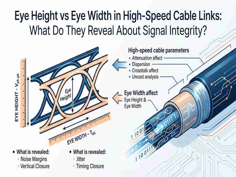
A high-speed cable can look healthy on an oscilloscope and still produce errors in the real system. That sounds contradictory until the two tests are separated by purpose. An eye diagram shows the electrical margin around a receiver decision, while BER measures whether those decisions actually turn into correct or incorrect bits over time. As data rates rise, the difference matters more because rare jitter events, pattern-dependent distortion, connector discontinuities, crosstalk, attenuation, and receiver behavior can hide behind an eye that appears comfortable during a short acquisition.

Read More »

Stay Ahead with Expert Insights

Want custom sourcing advice or technical answers? Subscribe to get new posts in your inbox or send your question directly to our engineer team.

Ask For A Quick Quote

We will contact you within 24 Hours, please pay attentionto the email with the suffx”@sino-conn.com”.