 Skip to content
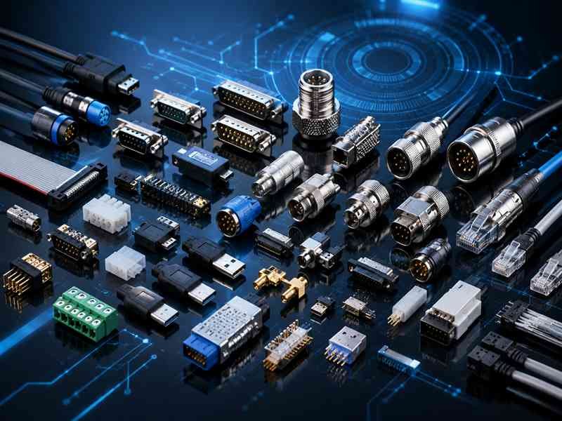
A connector looks like a small part, but in many electronic products, it decides whether the whole system works reliably or fails unexpectedly. A medical monitor may lose signal because of poor contact. An industrial robot may stop because vibration loosens a connector. A wireless device may show weak performance because the RF connector does not match the cable impedance. These are not rare problems. They are real issues engineers, purchasing teams, and OEM factories face every day.
Connectors are electromechanical parts used to join electrical circuits, cables, wires, PCB boards, or devices together. They allow power, signal, and data to pass through a system while keeping the connection removable, serviceable, and easier to assemble. Common connector types include wire connectors, RF connectors, USB connectors, circular connectors, waterproof connectors, and custom connectors for specific applications.
For many projects, choosing connectors is not only about matching a part number. Customers often need to confirm voltage, current, pitch, pin count, material, cable OD, shielding, impedance, locking structure, operating temperature, waterproof level, flame rating, flexibility, and certification requirements. If one detail is ignored, the connector may still fit physically but fail electrically or mechanically.
At Sino-Conn, many connector and cable assembly inquiries start from a very simple message: “Can you make this?” Sometimes the customer sends a drawing. Sometimes they only send a photo. Sometimes they have an original connector part number but want a more flexible compatible solution. The real work starts after that first question—checking the application, identifying the connector, confirming the cable structure, preparing drawings, building samples, and testing every finished assembly before shipment.
This guide explains what connectors are, which connector types are commonly used, and what customers should check before choosing a connector for a cable assembly project.
What Are Connectors?
Connectors are the physical interface that allows electricity, signals, or data to travel between two points in an electronic system. They may look like small components, but they directly influence whether a product operates reliably, can be assembled efficiently, and remains serviceable throughout its lifecycle.
Every electronic system contains connection points. A medical monitor must connect sensors to control boards. A robot must connect motors, cameras, and controllers. A communication device must connect antennas, power supplies, and data interfaces. Without connectors, these connections would need to be permanently soldered together, making manufacturing, maintenance, upgrades, and repairs extremely difficult.
In modern product design, connectors are no longer viewed as simple accessories. They are considered critical system components because they affect electrical performance, mechanical reliability, installation efficiency, maintenance costs, and product lifespan.
For many customers contacting Sino-Conn, the connector is often one of the least understood parts of the project. Engineers usually focus on PCB design, software, sensors, displays, or communication protocols. Purchasing teams focus on cost and delivery. However, connector selection often becomes a hidden factor that determines whether a product performs reliably in real-world conditions.
A connector that costs only a few dollars can sometimes protect equipment worth thousands or even tens of thousands of dollars.
What Is a Connector?
A connector is an electromechanical device designed to create a removable connection between electrical circuits, cables, wires, PCBs, or electronic equipment.
The key word is “removable.”
Unlike soldered joints, connectors allow devices to be disconnected and reconnected without damaging the system. This flexibility makes manufacturing faster, maintenance easier, and product upgrades more practical.
Most connectors contain several important elements working together:
| Component | Function | Impact on Performance |
|---|---|---|
| Housing | Holds terminals in position | Mechanical stability |
| Contacts | Conduct current or signal | Electrical performance |
| Insulator | Separates contacts | Safety and reliability |
| Locking Mechanism | Prevents accidental disconnects | Vibration resistance |
| Shielding Structure | Reduces EMI | Signal quality |
| Sealing Components | Protect against water and dust | Environmental protection |
| Strain Relief | Protects cable exit area | Longer service life |
The complexity of connectors varies greatly depending on the application.
For example:
| Application | Typical Connector Complexity |
|---|---|
| LED Lighting | 2-4 contacts |
| Industrial Sensors | 4-12 contacts |
| USB Interfaces | 4-24 contacts |
| Medical Imaging Systems | 20-100+ contacts |
| Aerospace Systems | Hundreds of contacts possible |
This explains why two connectors that look almost identical externally may have completely different specifications internally.
A connector used for charging a device may carry several amps of current, while another connector of similar size may be transmitting high-speed data at several gigabits per second.
Selecting based on appearance alone is one of the most common mistakes seen in sourcing projects.
How Do Connectors Work?
At their most basic level, connectors work by creating a controlled electrical contact between conductive terminals.
When the male and female sides mate together, metal contacts touch under carefully designed pressure. This pressure creates a stable conductive path through which power, signals, or data can travel.
The challenge is maintaining that connection over time.
A connector may experience:
- Vibration
- Mechanical shock
- Repeated mating cycles
- Temperature changes
- Moisture exposure
- Dust contamination
- Chemical exposure
- Continuous cable movement
Each of these conditions can affect contact quality.
For example, in a robotic system, a connector may experience thousands of bending cycles every week. In an outdoor communication system, a connector may be exposed to rain, UV radiation, and temperature fluctuations for years. In medical equipment, signal quality may need to remain stable even after repeated cleaning and maintenance procedures.
The table below illustrates how different connector design factors affect performance:
| Design Factor | Customer Benefit |
|---|---|
| Gold-Plated Contacts | Lower contact resistance and corrosion |
| Positive Locking | Reduced accidental disconnection |
| Shielded Housing | Better EMI performance |
| Waterproof Seals | Longer outdoor service life |
| High Cycle Rating | Suitable for repeated use |
| Precision Terminals | Stable signal transmission |
This is one reason why connector specifications are often much more detailed than customers initially expect.
When Sino-Conn provides connector specifications, customers frequently request information such as:
- Voltage rating
- Current rating
- Contact resistance
- Insulation resistance
- Operating temperature
- Material type
- Cable OD compatibility
- Shielding structure
- Mating cycles
- Flame rating
- UV resistance
- Oil resistance
- Halogen-free requirements
- PFAS compliance
Each specification contributes to the connector’s ability to perform reliably in its intended environment.
Why Are Connectors Important?
Many electronic failures are eventually traced back to connection problems.
In field applications, failures often originate at connection points rather than within the cable itself.
A loose terminal, incorrect pin assignment, insufficient strain relief, damaged contact, or poor sealing structure can all cause unexpected downtime.
The financial impact can be surprisingly large.
Consider the following examples:
| Industry | Cost of Connector Failure |
|---|---|
| Industrial Automation | Production downtime |
| Medical Equipment | Service interruptions |
| Telecommunications | Network disruption |
| Robotics | Equipment stoppage |
| Test Equipment | Inaccurate measurements |
| Transportation Systems | Safety concerns |
For OEM manufacturers, connector reliability directly affects warranty costs.
For engineers, connector performance affects validation results.
For purchasing teams, connector quality affects supplier evaluation and customer satisfaction.
For end users, connectors often determine whether equipment works consistently or becomes a source of ongoing maintenance issues.
One industrial customer approached Sino-Conn after experiencing recurring failures on a motor control cable assembly.
The original connector met the electrical requirements on paper but lacked sufficient strain relief. Continuous cable movement gradually damaged the conductors near the connector exit point.
The connector itself was not defective.
The application requirements had simply not been fully considered during the original design stage.
After redesigning the strain relief structure and updating the cable routing, the assembly achieved a significantly longer service life.
This illustrates an important lesson:
A connector should not be evaluated only by its datasheet.
It should be evaluated by how it performs in the actual application.
Where Are Connectors Used?
Connectors are found in almost every modern industry because nearly every electronic system depends on reliable electrical connections.
The variety of applications continues to grow as products become more connected, automated, and data-driven.
Some common examples include:
| Industry | Connector Applications |
|---|---|
| Medical | Ultrasound systems, patient monitors, imaging equipment |
| Industrial Automation | PLCs, sensors, motors, servo systems |
| Robotics | Cameras, motion controllers, power systems |
| Telecommunications | Antennas, base stations, network equipment |
| Automotive | ADAS systems, displays, sensors |
| Aerospace | Avionics and communication systems |
| Consumer Electronics | Computers, charging devices, displays |
| Test Equipment | Oscilloscopes, measurement systems |
At Sino-Conn, connector inquiries come from a wide range of industries.
Some customers provide complete engineering drawings and detailed specifications.
Others provide only:
- A connector photo
- An old cable sample
- A competitor product
- A hand-drawn sketch
- A device photo
One recent customer from the robotics sector sent only several photographs of a damaged cable assembly removed from a robotic arm.
No part numbers were visible.
No drawings existed.
The goal was simply to create a replacement assembly with improved reliability.
After identifying the connector family, measuring cable dimensions, confirming pin assignments, and generating engineering drawings, sample assemblies were produced for testing.
The customer later adopted the new assembly for ongoing production.
Situations like this are common because many products remain in service for years after the original documentation has disappeared.
This is why connector suppliers need more than manufacturing capability.
They need engineering capability as well.
The ability to identify unknown connectors, recommend alternatives, generate drawings, and support custom cable assemblies often saves customers significant time during product development and maintenance projects.
As electronic systems become smaller, faster, and more connected, the role of connectors continues to grow. Whether the application involves power transmission, signal integrity, waterproof protection, RF communication, or high-speed data transfer, the connector remains one of the most important components in the entire system.
Which Connectors Are Most Common?
Connectors come in thousands of configurations, but most cable assembly and electronic projects rely on a relatively small number of connector categories. Understanding these common connector types helps engineers make better design decisions, helps purchasing teams communicate more effectively with suppliers, and helps OEM manufacturers avoid costly mistakes during product development.
One reason connector selection can be confusing is that many connectors look similar from the outside. Two connectors may have the same number of pins and nearly identical dimensions, yet support completely different voltages, currents, signal speeds, environmental ratings, or mating cycles.
In practice, the “best” connector is usually not the most expensive connector or the most advanced connector. It is the connector that matches the electrical requirements, installation space, operating environment, maintenance expectations, and budget of the project.
At Sino-Conn, inquiries involving connector identification are extremely common. Many customers arrive with only a connector photo, a cable sample, or a product image from a competitor. In these situations, understanding connector categories becomes the first step toward finding a workable solution.
What Are Wire Connectors?
Wire connectors are the most widely used connector family in the electronics industry.

Almost every electronic device contains wire connectors somewhere inside the product. They are used to connect wires to PCBs, wires to sensors, wires to displays, batteries, motors, power supplies, and communication modules.
Although they may appear simple, wire connectors account for a significant portion of all connector applications worldwide.
Common wire connector families include:
| Connector Type | Common Applications |
|---|---|
| Wire-to-Wire | Cable extensions, battery systems |
| Wire-to-Board | PCB connections |
| IDC Connectors | Ribbon cable assemblies |
| Crimp Connectors | Industrial wiring |
| Terminal Blocks | Power distribution |
| Board-In Connectors | Compact electronics |
Wire connector selection is heavily influenced by several factors:
| Selection Factor | Common Values |
|---|---|
| Pitch | 1.0mm, 1.25mm, 2.0mm, 2.54mm, 3.96mm |
| Pin Count | 2 to 50+ positions |
| Current Rating | 1A to 20A+ |
| Wire Gauge | 30AWG to 12AWG |
| Locking Style | Friction, latch, snap, screw |
| Mating Cycles | 50 to 5000+ |
Many customers underestimate the importance of matching wire gauge and current rating.
For example, a connector designed for 28AWG signal wire may physically accept a larger conductor but generate excessive heat when carrying higher current loads. Over time, this can cause terminal damage, insulation degradation, or intermittent failures.
One automation customer approached Sino-Conn after experiencing connector overheating in a control cabinet. The original connector was selected primarily because it fit the available space. After reviewing the application, it became clear that the connector’s current rating was too close to the system’s operating load.
A higher-rated connector and heavier wire gauge solved the issue without requiring changes to the rest of the system.
This illustrates an important point: connector dimensions alone should never drive connector selection.
What Are RF Connectors?
RF connectors are specifically designed to carry radio frequency signals while maintaining controlled impedance and minimizing signal loss.

Unlike standard wire connectors, RF connectors operate in environments where even small changes in impedance can affect performance.
This is especially important in applications such as:
- Wireless communication systems
- GPS equipment
- Cellular infrastructure
- Industrial wireless networks
- Medical imaging systems
- Drone communication systems
- RF test equipment
- Antenna assemblies
The most common RF connector families include:
| RF Connector | Typical Frequency Range | Common Applications |
|---|---|---|
| SMA | Up to 18 GHz or higher | RF modules, antennas |
| SMB | Up to 4 GHz | Compact communication systems |
| BNC | Up to 4 GHz | Test equipment |
| TNC | Up to 11 GHz | Outdoor communication |
| N-Type | Up to 18 GHz | Base stations |
| MMCX | Up to 6 GHz | Compact devices |
| U.FL / IPEX | Up to 6 GHz | Internal antennas |
Signal loss becomes increasingly important as frequencies rise.
The table below illustrates why cable and connector matching matters:
| Frequency | Small Impedance Error Impact |
|---|---|
| Below 100 MHz | Often minimal |
| 500 MHz | Noticeable |
| 1 GHz | Significant |
| 5 GHz | Critical |
| 10 GHz+ | Extremely critical |
A common mistake is focusing entirely on the connector while ignoring the cable.
A premium RF connector cannot compensate for a poor cable choice.
Likewise, a high-quality coaxial cable may still perform poorly if improperly terminated.
At Sino-Conn, RF cable assembly projects typically involve reviewing:
- Connector type
- Cable impedance
- Frequency requirements
- Cable length
- Shielding structure
- Installation environment
- Connector orientation
This approach helps customers avoid performance problems before production begins.
What Are USB Connectors?
USB connectors have become one of the most recognizable connector families in the world.

What started as a simple computer interface has evolved into a universal platform for power delivery, data transfer, communication, video transmission, and embedded system connectivity.
Today, USB connectors are used in:
- Industrial automation
- Medical equipment
- Robotics
- Machine vision systems
- AI computing hardware
- Portable instruments
- Embedded electronics
- Consumer devices
The most common USB connector types include:
| USB Type | Common Application |
|---|---|
| USB-A | Computers and chargers |
| USB-B | Printers and industrial devices |
| Mini USB | Legacy equipment |
| Micro USB | Portable electronics |
| USB-C | Modern devices and communication systems |
USB-C has become particularly important because of its flexibility.
Depending on the design, a USB-C assembly may support:
- Power delivery
- USB 2.0 communication
- High-speed data
- Video output
- Device programming
- Embedded system debugging
However, not all USB-C assemblies are wired identically.
This creates confusion for many customers.
For example:
| USB-C Application | Wiring Complexity |
|---|---|
| Charging Only | Low |
| USB 2.0 Data | Moderate |
| USB 3.x Data | High |
| Video Transmission | Very High |
| Custom Industrial Communication | Application Specific |
One customer contacted Sino-Conn requesting a USB-C cable that looked identical to an existing product.
After discussing the application, it became clear that the cable required:
- Dual CC lines
- Full USB 2.0 connectivity
- SBU lines
- EMI shielding
Although externally identical, the internal wiring was significantly different from a standard charging cable.
This situation is far more common than many buyers realize.
What Are Circular Connectors?
Circular connectors are among the most durable connector families available.

Their round housing design provides excellent mechanical strength, reliable alignment, and effective sealing options.
These connectors are widely used in:
- Industrial automation
- Servo systems
- Sensors
- Motors
- Medical equipment
- Transportation systems
- Outdoor equipment
- Robotics
Popular circular connector families include:
| Connector Family | Typical Use |
|---|---|
| M5 | Miniature sensors |
| M8 | Compact industrial devices |
| M12 | Sensors and industrial Ethernet |
| M16 | Control systems |
| M23 | Servo motors |
| Push-Pull | Medical equipment |
| Aviation Connectors | Industrial equipment |
One reason circular connectors remain popular is their ability to withstand vibration.
Many include:
- Threaded locking
- Bayonet locking
- Push-pull locking
- Waterproof sealing
For industrial applications, connector durability often matters more than connector size.
An M12 connector installed in a factory may operate continuously for years while experiencing vibration, temperature changes, and frequent maintenance activity.
At Sino-Conn, circular connector projects frequently involve custom cable assemblies where customers require:
- Specific cable lengths
- Shielded constructions
- Right-angle configurations
- Custom pin assignments
- Overmolded structures
These customizations help simplify installation while improving long-term reliability.
What Are Waterproof Connectors?
Waterproof connectors are designed to protect electrical systems from water, dust, humidity, and environmental contamination.

Demand for waterproof connectors continues to grow as more equipment moves outdoors or operates in harsh environments.
Common industries using waterproof connectors include:
- LED lighting
- Agriculture
- Marine systems
- Transportation
- Renewable energy
- Security systems
- Outdoor communications
- Industrial automation
The most common protection standards are:
| Protection Level | Typical Capability |
|---|---|
| IP65 | Water spray protection |
| IP67 | Temporary immersion |
| IP68 | Extended immersion |
| IP69K | High-pressure washdown |
Many customers focus only on the connector rating itself.
In reality, waterproof performance depends on the complete assembly.
Several elements work together:
- Connector housing
- Gaskets
- Cable seals
- Overmolding
- Cable jacket
- Assembly process
One outdoor monitoring equipment manufacturer approached Sino-Conn after experiencing water ingress problems despite using IP67-rated connectors.
After inspection, the issue was not the connector.
The cable outer diameter was smaller than the sealing range specified by the connector manufacturer.
This prevented the seal from compressing properly.
After updating the cable structure and sealing design, the issue was eliminated.
This example highlights an important lesson:
A waterproof connector is only as effective as the cable assembly surrounding it.
For outdoor systems, reviewing the complete assembly is often more important than focusing solely on the connector specification.
As electronic systems become more connected and more specialized, these five connector categories—wire connectors, RF connectors, USB connectors, circular connectors, and waterproof connectors—continue to dominate new product development across industrial, medical, communication, robotics, transportation, and consumer markets.
Understanding how each connector category works makes it much easier to select the right solution, reduce project risk, and avoid expensive redesigns later in the development process.
How Do You Choose Connectors?
Selecting a connector is often more complicated than selecting a cable.
Many engineers spend weeks designing PCBs, selecting processors, optimizing software, and validating system performance, yet connector selection is sometimes treated as an afterthought. In reality, connectors sit at the intersection of electrical performance, mechanical design, manufacturing efficiency, field maintenance, and long-term reliability.
A connector may only represent a small percentage of the total product cost, but it frequently becomes one of the most critical components in the entire system.
At Sino-Conn, connector selection discussions often begin with a simple question:
“Can this connector work?”
A better question is:
“Will this connector continue working reliably for the next five years in the actual application?”
The answer depends on many factors including electrical requirements, environmental conditions, installation constraints, maintenance expectations, production volume, and supply chain stability.
The goal is not simply to find a connector that fits.
The goal is to find a connector that continues performing reliably throughout the product’s lifecycle.
Which Connector Fits Your Application?
Every connector is designed for a specific purpose.
A connector that performs perfectly inside a desktop computer may fail quickly inside a robot arm. A connector suitable for charging a consumer device may be completely unsuitable for a medical imaging system.
Before selecting any connector, it is important to understand what the connector is actually required to do.
The first questions engineers should ask include:
| Question | Why It Matters |
|---|---|
| Is it carrying power or signals? | Determines current and voltage requirements |
| Is data transmission involved? | Determines signal integrity requirements |
| Is RF involved? | Requires impedance control |
| Will the connector move? | Influences locking and strain relief design |
| Is maintenance required? | Impacts mating cycle requirements |
| Is space limited? | Determines connector size and orientation |
Different applications place different priorities on connector performance.
| Application | Primary Connector Requirement |
|---|---|
| Medical Device | Reliability and signal quality |
| Industrial Automation | Durability and vibration resistance |
| Robotics | Flexibility and bending performance |
| Communication Equipment | Signal integrity |
| Consumer Electronics | Cost and compact size |
| Outdoor Equipment | Waterproof protection |
One robotics customer contacted Sino-Conn because their original connector continuously failed after several months of operation.
The connector itself was not defective.
The issue was that the cable assembly experienced continuous movement exceeding the connector’s intended application. By redesigning the connector orientation and improving cable strain relief, service life increased substantially.
This demonstrates why application understanding should always come before connector selection.
Which Connector Fits Your Environment?
Environmental conditions are responsible for a large percentage of connector failures.
A connector operating in a clean laboratory experiences very different conditions than one installed on agricultural equipment, factory machinery, or outdoor communication infrastructure.
Ignoring environmental factors often leads to expensive field failures.
Several environmental conditions should be evaluated early:
| Environmental Factor | Connector Impact |
|---|---|
| Temperature | Material stability |
| Humidity | Corrosion risk |
| Dust | Contact contamination |
| Water | Seal requirements |
| Oil | Material compatibility |
| UV Exposure | Housing degradation |
| Vibration | Connector loosening |
| Chemicals | Material resistance |
Temperature alone can significantly affect connector performance.
For example:
| Temperature Range | Common Considerations |
|---|---|
| 0°C to 40°C | Standard commercial applications |
| -20°C to 85°C | Industrial equipment |
| -40°C to 125°C | Automotive systems |
| Above 150°C | Specialized applications |
Many customers focus on electrical specifications while overlooking environmental conditions.
A connector may pass all laboratory testing yet fail prematurely when exposed to:
- Factory oils
- Cleaning chemicals
- Salt spray
- UV radiation
- Continuous vibration
One outdoor surveillance equipment manufacturer approached Sino-Conn after experiencing repeated connector failures.
The original connector met the required IP rating, but the housing material was not designed for prolonged UV exposure. Over time, the plastic became brittle and cracked.
After switching to a more suitable material and reviewing the complete cable assembly design, reliability improved significantly.
The lesson is simple:
The environment often determines connector lifespan more than the electrical load itself.
How Important Is EMI Shielding?
Electromagnetic interference is often discovered only after a system enters testing or field operation.
Everything may appear to work correctly during early development, but once multiple electronic systems are installed together, unexpected communication issues can appear.
Common symptoms include:
- Unstable data transmission
- Sensor errors
- Communication interruptions
- Video distortion
- RF performance degradation
- Unexpected system resets
In many cases, insufficient shielding is the root cause.
Connectors play an important role in overall EMI performance because every connection point can potentially become a source of interference or a path for unwanted noise.
Applications where shielding is particularly important include:
| Application | Shielding Importance |
|---|---|
| RF Systems | Extremely High |
| Medical Imaging | Extremely High |
| Industrial Ethernet | High |
| Machine Vision | High |
| Servo Systems | High |
| AI Computing Hardware | High |
| High-Speed USB | High |
Shielding solutions commonly include:
- Foil shielding
- Braided shielding
- Combination shielding
- Metal connector shells
- Grounded connector designs
A common mistake is assuming the cable shielding alone provides sufficient protection.
The connector termination must also maintain shielding continuity.
For example, a shielded cable connected to a plastic connector without proper grounding may lose much of its shielding effectiveness.
At Sino-Conn, EMI-related projects often involve reviewing the complete signal path rather than only the connector itself. This includes cable construction, shielding termination, grounding methods, connector materials, and assembly techniques.
In high-speed communication systems, medical equipment, and RF applications, shielding performance can directly influence product certification, system stability, and customer satisfaction.
How Do You Compare Connector Types?
Comparing connectors requires looking beyond appearance and price.
Two connectors may seem similar but perform very differently depending on the application.
The table below illustrates some common trade-offs:
| Connector Type | Advantages | Limitations |
|---|---|---|
| Wire Connector | Economical, versatile | Limited environmental protection |
| RF Connector | Excellent signal performance | Higher assembly precision required |
| USB Connector | Universal compatibility | Application-specific wiring |
| Circular Connector | Strong mechanical reliability | Larger physical size |
| Waterproof Connector | Environmental protection | Higher cost |
| Push-Pull Connector | Fast operation | Premium pricing |
When evaluating connectors, engineers typically compare:
| Selection Criteria | Importance |
|---|---|
| Voltage Rating | Safety |
| Current Rating | Thermal performance |
| Contact Resistance | Signal quality |
| Mating Cycles | Service life |
| Locking Mechanism | Mechanical security |
| Shielding | EMI control |
| Size | Installation space |
| Cost | Budget control |
| Lead Time | Production planning |
A connector should be evaluated as part of the complete system rather than as an individual component.
For example, selecting a miniature connector may save space but create assembly challenges.
Selecting a highly rugged connector may improve durability but increase cost and installation complexity.
The best connector usually balances performance, reliability, availability, and cost.
Original or Compatible Connectors?
This is one of the most common topics discussed with customers.
Many projects begin with a specific connector part number from a well-known manufacturer. However, supply chain conditions, lead times, MOQ requirements, and project budgets often create interest in compatible alternatives.
The decision should be based on project requirements rather than assumptions.
| Factor | Original Connector | Compatible Connector |
|---|---|---|
| Cost | Higher | Lower |
| Availability | Sometimes Limited | Often Better |
| Lead Time | Longer | Faster |
| MOQ | Higher | More Flexible |
| Customization | Limited | More Flexible |
| Fit and Function | Original Specification | Equivalent Application Performance |
For engineering validation projects, prototype development, maintenance replacement, and many industrial applications, compatible connectors can offer significant advantages.
Several customers working with Sino-Conn have chosen compatible connectors because:
- Production schedules could not wait for original lead times.
- Prototype quantities were too small for original MOQ requirements.
- Existing products required custom cable modifications.
- Budget constraints favored alternative solutions.
One customer developing a communication device required a specific connector family from a major international brand. Lead times exceeded twelve weeks.
After technical evaluation, a compatible connector solution was tested and approved for development work. The customer was able to continue product validation immediately while maintaining the option to switch to original connectors later if required.
This approach reduced project delays and accelerated development.
The most successful connector projects rarely begin by asking:
“What is the cheapest connector?”
Instead, they begin by asking:
“What connector solution best supports the product, the schedule, and the long-term business goals?”
That shift in thinking often leads to better technical decisions, fewer production issues, and a more reliable finished product.
How Are Custom Connectors Made?
Many people hear the phrase “custom connector” and immediately imagine a completely new connector being designed from scratch.
In reality, most custom connector projects are not about inventing a new connector. They are about modifying, adapting, or integrating existing connector platforms into a cable assembly that solves a specific problem.
This distinction is important because it directly affects project cost, development time, tooling requirements, and production risk.
For example, a customer may need:
- A non-standard cable length
- A special pin assignment
- A different cable material
- A unique overmolded shape
- Improved shielding
- Better waterproof performance
- A connector orientation that fits a tight installation space
The connector itself may remain unchanged, while the cable assembly becomes highly customized.
At Sino-Conn, most custom connector projects fall into this category. Customers are rarely asking for a completely new connector design. They are usually trying to solve an application challenge that standard products cannot address.
A successful custom connector project typically follows a structured process involving engineering review, drawing creation, material selection, sample validation, production, and testing.
How Are Connectors Designed?
Every custom connector project starts with information gathering.
The quality of the final product depends heavily on the quality of information collected during the early stages.
Customers generally fall into several categories:
| Customer Type | Information Usually Provided |
|---|---|
| Design Engineer | Drawings, specifications, requirements |
| OEM Factory | BOM, drawings, quantities |
| Purchasing Team | Part number or existing supplier information |
| Distributor | Product photos and basic descriptions |
| Maintenance Team | Existing sample or damaged assembly |
The amount of information varies dramatically.
Some projects arrive with complete technical packages containing:
- Connector part numbers
- Cable specifications
- Pin assignments
- 3D drawings
- Electrical requirements
- Testing standards
Other projects begin with a simple message:
“Can you make this cable?”
Along with several photos.
Both situations are common.
The first stage of connector design usually involves collecting information such as:
| Design Parameter | Typical Requirement |
|---|---|
| Voltage | 5V to 1000V+ |
| Current | mA to hundreds of amps |
| Signal Type | Power, data, RF, video |
| Wire Gauge | AWG size |
| Cable OD | Mechanical compatibility |
| Shielding | EMI protection |
| Operating Temperature | Environmental suitability |
| Waterproof Level | IP requirements |
| Flexibility | Static or dynamic use |
At Sino-Conn, engineering reviews often uncover missing information before production begins.
For example, a customer may specify the connector model but not the cable bending requirements. Another customer may specify cable length but overlook current requirements.
These details may seem minor initially, but they often determine long-term reliability.
How Are Connectors Customized?
Customization can occur at many different levels.
Most customers are surprised by how many variables can be adjusted without changing the connector family itself.
The most common customization options include:
| Customization Area | Examples |
|---|---|
| Cable Length | 100mm to 100m+ |
| Pinout | Custom wiring definitions |
| Cable Material | PVC, TPU, TPE, Silicone |
| Connector Orientation | Straight, right-angle, left-angle |
| Shielding | Foil, braid, hybrid |
| Jacket Color | Customer-specific colors |
| Overmolding | Customized shape and protection |
| Labeling | Logos, serial numbers, part numbers |
| Waterproofing | IP67, IP68 designs |
A practical example comes from a robotics customer.
The original cable assembly worked electrically but repeatedly failed during field operation.
The issue was not the connector.
The issue was cable routing.
The cable needed to pass through a moving axis with a tight bending radius.
After reviewing the application, the project was modified by:
- Changing cable material
- Improving strain relief
- Adjusting connector exit direction
- Optimizing cable routing
The connector remained the same.
The performance improved significantly.
This is often how custom connector projects work in practice.
Small design changes can have a major impact on reliability.
How Are Connectors Assembled?
Connector assembly combines multiple manufacturing processes into a finished product.
Each process affects final quality.
Even the best connector can perform poorly if assembly quality is inconsistent.
A typical custom connector assembly process includes:
| Manufacturing Step | Purpose |
|---|---|
| Wire Cutting | Length accuracy |
| Wire Stripping | Terminal preparation |
| Crimping | Electrical connection |
| Soldering | Special terminations |
| Terminal Insertion | Correct pin location |
| Shield Termination | EMI protection |
| Overmolding | Mechanical protection |
| Labeling | Product identification |
| Testing | Quality verification |
One of the most critical operations is crimping.
Poor crimps are responsible for many field failures.
A properly formed crimp creates both:
- Electrical connection
- Mechanical retention
Common crimp-related issues include:
- Under-crimping
- Over-crimping
- Broken strands
- Incomplete conductor insertion
- Damaged insulation support
Because of this, professional cable assembly production relies on controlled tooling, inspection procedures, and operator training.
At Sino-Conn, assembly teams work with detailed drawings approved by customers before production begins. This helps ensure that connector orientation, pin assignments, cable lengths, and other critical details remain consistent throughout manufacturing.
How Are Connectors Tested?
Testing is where a design becomes a verified product.
Without testing, there is no reliable way to confirm that the finished assembly matches customer requirements.
The level of testing depends on the application.
For consumer products, basic electrical verification may be sufficient.
For medical, industrial, communication, and military applications, testing requirements are often much stricter.
Common connector assembly tests include:
| Test | Purpose |
|---|---|
| Continuity Test | Verify electrical paths |
| Pinout Verification | Confirm wiring sequence |
| Insulation Resistance | Detect leakage paths |
| Hi-Pot Test | Verify insulation strength |
| Pull Force Test | Evaluate mechanical strength |
| Dimensional Inspection | Confirm assembly accuracy |
| Visual Inspection | Detect cosmetic defects |
| Functional Testing | Simulate real operation |
Many customers are surprised to learn how much testing occurs before shipment.
For example, a simple cable assembly containing 20 conductors may require verification of:
- 20 correct connections
- 190 potential short-circuit combinations
- Correct polarity
- Correct shielding termination
The complexity increases rapidly as pin counts grow.
At Sino-Conn, quality control generally includes multiple inspection stages:
| Inspection Stage | Objective |
|---|---|
| Incoming Material Inspection | Verify connector and cable quality |
| In-Process Inspection | Monitor assembly consistency |
| Finished Product Inspection | Verify assembly quality |
| Pre-Shipment Inspection | Final approval |
This layered approach helps identify problems before products reach customers.
How Are Connector Drawings Created?
Connector drawings are one of the most important documents in a custom connector project.
A drawing converts ideas into measurable specifications.
Without a drawing, misunderstandings become much more likely.
A good connector drawing typically includes:
| Information | Purpose |
|---|---|
| Connector Model | Component identification |
| Pin Assignment | Electrical definition |
| Cable Length | Mechanical specification |
| Wire Information | Electrical capability |
| Connector Orientation | Assembly accuracy |
| Material Information | Compliance verification |
| Revision History | Change management |
One reason customers choose custom cable assembly suppliers rather than distributors is drawing support.
Many distributors can provide part numbers.
Fewer suppliers can generate manufacturing drawings.
At Sino-Conn, drawing support is often a key part of the project.
Many customers begin with:
- Photos
- Existing samples
- Competitor products
- Hand sketches
- Legacy assemblies
Engineering teams then create:
- CAD drawings
- PDF drawings
- Wiring diagrams
- Pinout documentation
For standard projects, drawings are often completed within several days.
Simple projects can sometimes be completed within hours.
Before production begins, customers review and approve drawings.
This approval process significantly reduces the risk of misunderstandings regarding:
- Connector orientation
- Pin definitions
- Cable length
- Material selection
- Shielding structure
One industrial customer previously sourced assemblies from multiple suppliers and experienced repeated wiring inconsistencies.
After implementing a controlled drawing approval process, assembly errors were dramatically reduced.
The lesson was straightforward:
The drawing is not paperwork.
The drawing is the blueprint that connects engineering expectations to manufacturing reality.
The most successful custom connector projects are rarely the ones with the most complex technology. They are the ones where requirements are clearly defined, drawings are accurate, communication is efficient, and testing confirms that the finished product performs exactly as expected.
That is why custom connector manufacturing is not simply about building cables. It is about translating a customer’s application requirements into a reliable, repeatable, and manufacturable solution.
Which Connector Supplier Is Best?
Finding the right connector is only half of the challenge. The other half is finding a supplier that can consistently deliver the correct connector, the correct cable assembly, the correct documentation, and the correct support throughout the life of a project.
Many companies initially compare suppliers based on unit price alone. This approach often works for standard off-the-shelf products, but custom connector and cable assembly projects are different. A low quotation means very little if the supplier cannot identify a connector correctly, cannot support engineering changes, cannot provide drawings, or cannot maintain quality consistency during mass production.
The best connector supplier is not necessarily the cheapest supplier. The best connector supplier is the one that helps reduce project risk.
For engineers, that means technical support.
For OEM factories, that means stable production.
For purchasing teams, that means reliable delivery.
For distributors, that means fewer customer complaints.
For end users, that means dependable product performance.
At Sino-Conn, many new customers contact us after experiencing problems with previous suppliers. Interestingly, the most common complaints are rarely about connector technology itself. They are usually related to communication, quality consistency, lead times, documentation, or engineering support.
Choosing a connector supplier should therefore be viewed as selecting a long-term project partner rather than simply purchasing a component.
What Should a Connector Supplier Provide?
Many connector suppliers can sell connectors.
Far fewer suppliers can support a project from concept to production.
A professional connector supplier should provide far more than a quotation sheet.
The supplier should be capable of supporting engineering discussions, identifying risks, creating drawings, recommending materials, producing prototypes, and maintaining quality consistency throughout production.
The table below summarizes what customers typically need from a connector supplier:
| Support Capability | Why It Matters |
|---|---|
| Technical Consultation | Helps avoid design mistakes |
| Connector Identification | Useful when no part number exists |
| Drawing Support | Reduces communication errors |
| Material Specifications | Supports engineering approval |
| Prototype Production | Verifies design before mass production |
| Quality Documentation | Supports customer audits |
| Production Updates | Improves project visibility |
| Engineering Change Support | Allows design optimization |
A common situation at Sino-Conn involves customers who only have a product photograph.
No drawing.
No BOM.
No connector part number.
No supplier information.
Only a photograph.
For many suppliers, this becomes an obstacle.
For experienced engineering teams, it becomes the starting point.
By identifying the connector family, measuring dimensions, reviewing cable structure, and creating drawings, the project can move forward even when documentation is incomplete.
This capability becomes especially valuable for maintenance projects, legacy equipment, and products that have been in service for many years.
How Fast Can Connectors Be Delivered?
Lead time has become one of the most important purchasing factors in recent years.
Many product launches are delayed not because designs are incomplete, but because components are unavailable.
Connector lead times can vary dramatically depending on:
| Factor | Impact on Delivery |
|---|---|
| Connector Availability | Very High |
| Original vs Compatible Parts | High |
| Cable Material Availability | Medium |
| Production Volume | Medium |
| Testing Requirements | Medium |
| Custom Tooling | Medium |
For custom cable assemblies, delivery speed often depends on how quickly technical details can be confirmed.
A project with complete drawings may move into production immediately.
A project requiring connector identification, drawing creation, and engineering review will naturally take longer.
Typical project timelines at Sino-Conn are:
| Project Stage | Typical Time |
|---|---|
| Connector Identification | Same day to 2 days |
| Drawing Preparation | Within 3 days |
| Standard Samples | Around 2 weeks |
| Urgent Samples | 2–3 days |
| Batch Production | 3–4 weeks |
| Expedited Orders | Around 2 weeks |
Many customers underestimate the importance of fast engineering response.
A supplier who replies within hours can often save several days or even weeks during product development.
One robotics customer previously waited nearly a week for every drawing revision from another supplier. After switching projects to Sino-Conn, drawing revisions were typically completed within 24 hours, allowing the development team to move much faster.
The connector itself remained unchanged.
The project timeline improved significantly.
Can a Connector Supplier Support Small Orders?
Most successful products begin with small quantities.
Very few products start with an order for 10,000 pieces.
The development process usually follows a progression:
| Project Stage | Typical Quantity |
|---|---|
| Initial Prototype | 1–10 pcs |
| Functional Testing | 10–50 pcs |
| Engineering Validation | 50–200 pcs |
| Pilot Production | 200–1000 pcs |
| Mass Production | 1000+ pcs |
Unfortunately, many suppliers focus primarily on large-volume business and show limited interest in prototype projects.
This creates challenges for engineering teams.
A startup developing a medical device may only need five assemblies.
A robotics engineer may only require two prototypes.
A testing laboratory may need one custom cable.
If the supplier imposes high MOQ requirements, product development slows down.
One reason many engineers choose Sino-Conn is the ability to start with very small quantities.
There is no MOQ requirement.
Projects can begin from a single piece.
This flexibility allows engineers to validate designs before committing to larger production quantities.
Several long-term customers originally started with fewer than ten samples and later expanded into recurring production orders.
Supporting small projects is often the first step toward supporting large projects.
How Is Connector Quality Controlled?
Quality control is one of the most important indicators of a supplier’s capabilities.
A cable assembly may appear perfect externally while containing hidden problems internally.
Examples include:
- Incorrect pin assignments
- Damaged terminals
- Weak crimps
- Poor solder joints
- Incomplete shielding termination
- Wrong wire specifications
- Incorrect connector orientation
These problems are often difficult to detect after installation.
In industrial equipment, finding a wiring mistake after deployment can require hours of troubleshooting.
In medical equipment, downtime can become much more costly.
This is why quality systems matter.
At Sino-Conn, connector assemblies are subjected to multiple inspection stages.
| Inspection Stage | Purpose |
|---|---|
| Incoming Inspection | Verify materials |
| In-Process Inspection | Verify assembly quality |
| Finished Inspection | Verify completed product |
| Pre-Shipment Inspection | Final approval |
In addition to visual inspection, many projects also undergo:
| Test Type | Purpose |
|---|---|
| Continuity Test | Verify electrical connections |
| Pinout Verification | Confirm wiring sequence |
| Insulation Test | Detect shorts and leakage |
| Pull Force Test | Verify mechanical strength |
| Dimensional Inspection | Confirm assembly accuracy |
| Functional Testing | Simulate actual operation |
For many custom cable assemblies, 100% continuity testing and pinout verification are performed before shipment.
This significantly reduces the risk of field failures caused by assembly errors.
Customers in regulated industries often require additional documentation.
Common requests include:
- UL documentation
- RoHS declarations
- REACH declarations
- PFAS statements
- Material specifications
- COC
- COO
Providing these documents quickly can be just as important as delivering the product itself.
Why Do Customers Change Connector Suppliers?
Most supplier changes are not driven by price alone.
Customers often remain loyal to suppliers for years when projects are running smoothly.
Supplier changes usually occur when recurring problems begin affecting schedules, quality, or communication.
The most common reasons include:
| Reason | Customer Impact |
|---|---|
| Slow Response | Delayed projects |
| Long Lead Times | Missed deadlines |
| Poor Communication | Engineering confusion |
| Inconsistent Quality | Field failures |
| High MOQ | Development delays |
| Limited Engineering Support | Increased project risk |
| Inflexible Customization | Reduced design options |
One industrial automation customer contacted Sino-Conn after repeatedly encountering production delays.
The previous supplier could manufacture the assemblies but struggled with engineering revisions.
Every design change required lengthy communication cycles.
As a result, product development slowed significantly.
After transitioning the project, engineering drawings, prototype revisions, and sample updates were completed much faster, allowing the customer to meet launch schedules.
This situation is common across many industries.
Customers rarely switch suppliers because of one isolated issue.
They switch because several small problems gradually create larger project risks.
Why Do Engineers Prefer Technical Suppliers?
Engineers often evaluate suppliers differently than purchasing teams.
Purchasing departments naturally focus on:
- Price
- Lead time
- Payment terms
Engineers typically focus on:
- Technical capability
- Problem-solving ability
- Response speed
- Customization flexibility
- Product reliability
When development schedules are tight, technical support becomes extremely valuable.
One missing connector specification can delay a project.
One incorrect pin assignment can invalidate weeks of testing.
One misunderstood drawing revision can create costly production scrap.
This is why engineering support often becomes a major competitive advantage.
At Sino-Conn, technical discussions frequently involve:
- Connector recommendations
- Alternative connector solutions
- Shielding strategies
- Cable material selection
- Waterproof design
- Connector orientation optimization
- Drawing reviews
- Prototype validation
Many customers discover that these conversations save more money than negotiating a lower unit price.
Preventing a mistake is almost always less expensive than correcting one.
Why Choose Sino-Conn for Connector Projects?
Choosing a connector supplier ultimately comes down to reducing risk.
Customers need confidence that the supplier can understand requirements, create accurate drawings, manufacture consistently, and support future changes.
Sino-Conn supports customers across medical, industrial, robotics, communication, testing, AI hardware, and embedded electronics industries.
Key capabilities include:
| Capability | Sino-Conn Support |
|---|---|
| Connector Identification | From photos, samples, or part numbers |
| Drawing Creation | CAD and PDF support |
| Prototype Service | Starting from 1 piece |
| Fast Samples | As fast as 2–3 days |
| Custom Cable Assemblies | Length, pinout, material, shielding |
| Connector Options | Original and compatible solutions |
| Documentation | RoHS, REACH, PFAS, COC, COO and more |
| Quality Control | Multi-stage inspection process |
| Engineering Support | Direct technical communication |
Many projects begin with incomplete information.
Sometimes the customer has only a photograph.
Sometimes they have only an old cable.
Sometimes they simply know what the product needs to do.
That is enough to start the conversation.
The most successful connector projects are not necessarily the most complex ones. They are the projects where engineering requirements are clearly understood, communication is efficient, and the supplier can consistently transform ideas into reliable products.
That is ultimately what separates a connector vendor from a connector partner.
Final Thoughts
Connectors may appear to be small components, but they influence nearly every aspect of an electronic system.
The right connector can improve reliability, simplify assembly, reduce maintenance costs, and accelerate product development.
The wrong connector can create troubleshooting headaches, production delays, field failures, and unnecessary expenses.
Whether you are developing a medical device, industrial automation system, robotic platform, RF communication product, testing instrument, AI hardware platform, or custom electronic equipment, connector selection should be approached as an engineering decision rather than a purchasing decision.
The most successful projects typically begin with a clear understanding of:
- Electrical requirements
- Mechanical constraints
- Environmental conditions
- Compliance requirements
- Future production goals
Just as importantly, they begin with a supplier capable of supporting those requirements.
At Sino-Conn, we help customers move from ideas, samples, photos, and drawings to fully tested connector and cable assembly solutions.
Our team can support:
| Capability | Support |
|---|---|
| Connector Identification | From photos or samples |
| Engineering Drawings | CAD and PDF support |
| Custom Cable Assemblies | Length, pinout, material, shielding |
| Prototype Production | From 1 piece |
| Rapid Samples | As fast as 2–3 days |
| Batch Production | Typical 3–4 weeks |
| Quality Inspection | Multiple inspection stages |
| Documentation Support | RoHS, REACH, PFAS, COC, COO and more |
If you are currently searching for a connector solution, trying to identify an existing connector, developing a new product, or looking for a more responsive cable assembly partner, feel free to contact the Sino-Conn engineering team.
Even if all you have is a photo, an old sample, or a rough idea of what you need, we can help turn it into a manufacturable solution.
Many successful projects start with a simple question:
“Can you make this?”
The next one could be yours.


