 Skip to content

Electrical cable size sounds simple—just pick a number, match the conductor, and install it. But in real engineering, cable size is one of the most misunderstood variables. People assume size is only about “thickness” or AWG, when in reality, electrical cable size is a combination of conductor cross-section, insulation thickness, shielding structure, OD tolerance, twisting pattern, current loading, and even environmental temperature. Choosing the wrong size creates silent but dangerous failure modes: overheating, signal distortion, EMI noise, voltage loss, connector mismatch, and premature cracking.
The size of an electrical cable refers to its conductor cross-section (AWG or mm²), overall diameter (OD), insulation thickness, and shielding structure. Cable size directly affects current capacity, voltage drop, heat dissipation, bend radius, and connector compatibility. Selecting the correct size depends on electrical load, distance, temperature, installation environment, and industry standards. Proper sizing ensures safety, reliability, and long-term durability in all applications.
In practice, cable sizing is rarely straightforward. A customer may send Sino-conn a photo of a cable and say, “We need exactly this,” without realizing that the cable’s OD, strand count, and insulation thickness were originally chosen for a specific temperature limit, routing space, or connector type. One engineer once brought us a cable that kept failing inside a robotic arm. The conductor size was correct—but the insulation was too thick, making the cable stiff and forcing it to bend beyond its safe radius. After reducing OD by 0.4 mm and switching to finer strands, the machine ran two million cycles without failure.
Cable size is not a number. It is a performance strategy.
And the deeper you understand it, the fewer surprises your equipment will face.
Let’s break down what “cable size” truly means—and how to choose the right size for your application.
What Does Electrical Cable Size Actually Mean?
Electrical cable size refers to the conductor cross-sectional area (AWG or mm²), insulation thickness, shielding design, and overall diameter (OD). These dimensions determine current capacity, flexibility, voltage drop, heat dissipation, and connector compatibility. Cable size is not only about “thickness”—it is the combined effect of conductor structure, materials, and engineering requirements for the specific application.

Most people think cable size is the same as “AWG” or “mm²,” but professionals know that cable size is a multi-layer engineering decision. The conductor defines how much current a cable can safely carry, but insulation thickness affects voltage rating, environmental protection affects jacket size, and shielding determines how large the final OD becomes. Two cables with the same AWG can have completely different OD, flexibility, EMI behavior, and connector compatibility.
At Sino-conn, we see this misunderstanding every week. A customer sends us a photo of a cable from an old machine, expecting us to match it visually. But what they don’t realize is that the original manufacturer chose that size due to cabinet space constraints, thermal load, bend radius limits, or specific insulation requirements. Even a seemingly small OD difference of 0.2–0.4 mm can decide whether the cable fits through a grommet or fails a bending test.
Another common scenario: customers ask for “18AWG wire,” but do not mention the insulation thickness. An 18AWG conductor can have an OD of 2.0 mm, 2.4 mm, 3.2 mm, or even 4.0 mm depending on insulation and jacket. Without clarifying these details, connector mismatch or overheating can easily occur.
Cable size also impacts:
- Voltage drop over long distances
- Heat generation under continuous current
- Mechanical strength under pulling force
- Flexibility in robotic arms or moving chains
- EMI performance in sensitive electronics
- Compatibility with standard or custom connectors
From a manufacturing standpoint, Sino-conn evaluates cable size by mapping each project’s usage conditions:
Step 1 — Identify electrical load (current, voltage, resistance)
Step 2 — Determine environment (heat, oil, bending, UV)
Step 3 — Define insulation/jacket thickness
Step 4 — Adjust OD to match routing or connector needs
Step 5 — Confirm final size with CAD drawings in 30–180 minutes
Cable size is never random—it’s engineered. And choosing the right size ensures that no matter the application, the cable performs safely, consistently, and long-term.
What Parameters Define Cable Size? (AWG, mm², OD)
Electrical cable size is defined by three measurable values:
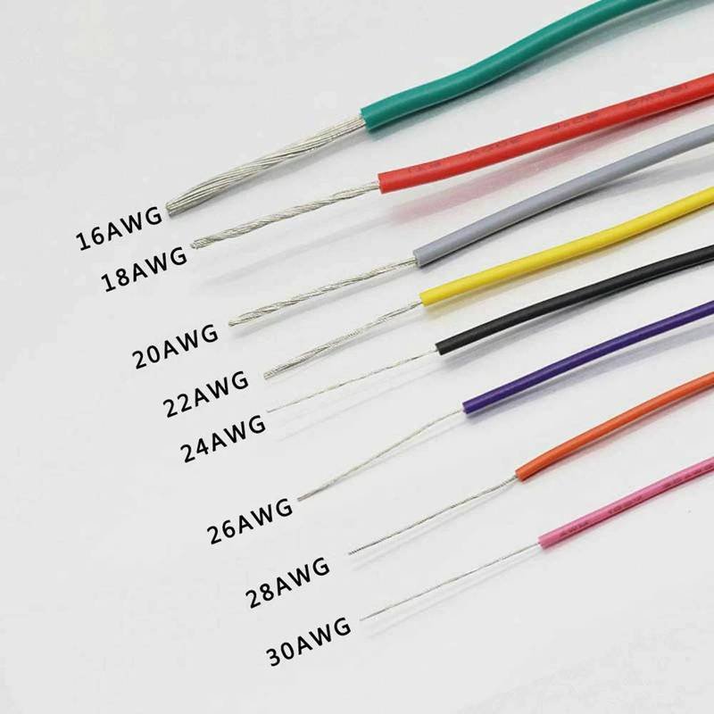
1) Conductor Size (AWG or mm²)
- Determines current-carrying ability
- Smaller AWG = thicker conductor
- Sino-conn supports 10AWG–34AWG and 0.02–16 mm²
2) Insulation Thickness
- Determines dielectric strength
- Influences OD and flexibility
3) Overall Diameter (OD)
- Affects routing space
- Must match connector openings
- Sino-conn controls OD within ±0.05–0.10 mm
A cable is “correct size” only when all three are optimized together.
How Do Diameter & Cross-Section Affect Current Capacity?
The larger the cross-sectional area of the conductor, the lower the resistance and the higher the current capacity. For example:
| Conductor Size | DC Resistance (Ω/km) | Typical Current |
|---|---|---|
| 24 AWG | ~85 Ω/km | 0.5–2A |
| 20 AWG | ~33 Ω/km | 3–5A |
| 16 AWG | ~13 Ω/km | 8–12A |
| 12 AWG | ~5.2 Ω/km | 12–20A |
Sino-conn performs resistance measurement on every spool before crimping or assembly.
Why Size Is More Than the Conductor?
Even with correct AWG, a cable may fail because:
- Insulation too thick → cable too stiff
- Shield braid too dense → OD too large
- Jacket too soft → poor abrasion resistance
- Filler too rigid → causes stress points
This is why Sino-conn analyzes structure layer by layer before finalizing drawings.
Which Cable Size Standards Are Common Today?
The most common cable size standards are AWG (American Wire Gauge), mm² (metric cross-sectional area), and OD (overall diameter). AWG is used mainly in the U.S., while mm² is used in Europe and Asia. Different industries—telecom, automotive, medical, and automation—use their own preferred size formats. Sino-conn supports all major sizing standards and provides fast drawings to help customers convert between AWG and mm².

Cable size standards vary globally, which often confuses buyers. A U.S. customer may request 22 AWG, while a European engineer asks for 0.34 mm²—both meaning nearly the same conductor size. Meanwhile, Japan may specify OD first, while automation engineers focus on flexibility and strand count. This inconsistency makes cross-border sourcing difficult, especially when customers rely on old supplier drawings or outdated product codes.
At Sino-conn, we routinely help customers translate between standards. For example:
- A German engineer sends a datasheet specifying “0.14 mm².”
- A U.S. distributor asks for “26 AWG twisted pair.”
- A Japanese OEM requests “2.2 mm OD max.”
Even though all refer to “cable size,” each uses a different measurement language.
AWG is logarithmic: every 3 steps roughly double the cross-sectional area. mm² is linear and more intuitive. OD varies depending on insulation and jacket type. When customers mix these standards, misunderstandings occur—leading to cables that cannot fit connectors, fail bend radius tests, or overheat during operation.
Sino-conn’s engineering team solves this by generating conversion-based drawings within 30–180 minutes. These drawings show:
- Conductor size (AWG + mm²)
- Strand count (e.g., 19/0.16)
- Insulation thickness
- Shield structure
- Final OD
- Connector compatibility
- Pin-out mapping
We create these drawings for every order, even prototypes, ensuring the cable size is understood correctly before production.
Sino-conn supports all global sizing systems:
AWG (U.S.–dominated markets)
mm² (EU, China, SE Asia)
OD-based classification (Japan, robotics industries)
Core count & pair layout (telecom, audio)
Special automotive and EV sizes (e.g., 25 mm², 35 mm² battery cables)
Each industry has its preferred sizing approach:
| Industry | Common Size System | Notes |
|---|---|---|
| Telecom | AWG + OD | Focus on impedance & attenuation |
| Robotics | OD + strand count | Flexibility is key |
| Medical | mm² + insulation rating | Halogen-free required |
| Consumer Electronics | AWG | USB, HDMI, LVDS rely on precise AWG |
| Automotive/EV | mm² | High-current applications |
Size standardization is not about numbers—it’s about application logic. Sino-conn’s role is to translate the customer’s language into manufacturable specifications.
What Is the Difference Between AWG and mm²?
- AWG decreases as wire becomes thicker
- mm² increases as wire becomes thicker
- AWG is logarithmic; mm² is linear
- Sino-conn provides conversion charts and ensures resistance math is correct
Example:
| AWG | mm² |
|---|---|
| 26 | 0.14 |
| 24 | 0.22 |
| 22 | 0.34 |
| 20 | 0.50 |
| 18 | 0.75 |
Are Size Rules Different Across Countries?
Yes:
- U.S. → AWG
- Europe → mm²
- Japan → OD + core layout
- Middle East → UL-style sizing
- Automotive → mm² only
- Robotics → OD tolerance is more important than AWG
Sino-conn adapts drawings based on the target market.
Which Size Standards Does Sino-conn Support?
Sino-conn supports:
- 30+ AWG classes
- mm² from 0.02 to 16 mm²
- OD tolerances ±0.05–0.10 mm
- Multi-core, twisted pairs, coax sizes
- Strip lengths, pin-outs, custom OD requirements
How Do Current, Voltage & Temperature Influence Cable Size?
Electrical cable size is determined by the combined effect of current load, voltage rating, temperature environment, and installation distance. Higher current requires a larger conductor to reduce heat and resistance; higher voltage needs thicker insulation; long distances increase voltage drop; and elevated temperatures reduce ampacity. Sino-conn evaluates these factors using real resistance data, derating curves, and thermal measurements to recommend the correct conductor size and insulation thickness for every application.
Current, voltage, and temperature are the three forces that shape how an electrical cable behaves under real working conditions. Most failures we see at Sino-conn—overheated insulation, brittle jackets, unstable voltage at the load, random signal noise—are caused by cables that were sized according to theory, not actual conditions inside the machine.
Current = heat + resistance
Whenever current flows through a conductor, it generates heat. If the conductor cross-section is too small, heat accumulates faster than it dissipates. In some customer cases, PVC insulation reached 95–105°C, even though the equipment environment was only 40–50°C. This happens when the conductor is sized only according to tables, without accounting for installation density and continuous load.
Sino-conn solves this by using actual measured resistance (Ω/km) from our copper spools—not catalog values. Our resistance tolerance is ±2%, which allows accurate voltage-drop and ampacity calculations.
Voltage = insulation thickness + dielectric strength
Voltage does not change the conductor size directly, but it determines how thick and how strong the insulation must be. For example:
- 300V → PVC insulation thickness around 0.45–0.55 mm
- 600V → PVC/XLPE insulation thickness around 0.7–0.9 mm
- 1000V → XLPE or rubber insulation, thickness often >1.0 mm
When Sino-conn receives projects for 600V or 1000V systems (EV chargers, industrial machines), our engineering team increases insulation thickness and uses materials with higher dielectric strength, such as 125°C XLPE. We also control eccentricity during extrusion to ensure uniform thickness with variance < 10%.
Temperature = real-world ampacity
All conductors have a temperature limit. Exceeding it causes:
- insulation to harden
- jacket to shrink or crack
- copper to oxidize
- long-term resistance increase
PVC is typically rated for 80°C, XLPE for 105–125°C, silicone for 180–200°C.
But in real equipment, ambient temperature is rarely at laboratory conditions. A cable routed near a transformer, motor, or power supply may see 65–85°C continuously.
This is where Sino-conn applies derating.
Temperature Derating Example (Real Sino-conn Case)
Customer requirement:
- 24AWG conductor
- 2.5A continuous current
- Inside a sealed metal housing (estimated internal 70°C)
According to UL charts:
- 24AWG can carry up to 3.5A in free air
But derating at 70°C reduces safe ampacity to ~1.8–2A.
The cable began to discolor after 3 months.
Sino-conn’s solution:
- Upgrade conductor to 22 AWG (0.34 mm²)
- Switch insulation to XLPE (125°C)
- Increase OD by only 0.12 mm
- Heat test at 75°C × 72 hours
Result:
- Temperature stabilized at 58–62°C
- Cable lifespan increased over 5×
This is why Sino-conn always requests current, distance, and environment details before quoting or drawing.
How Do You Calculate the Correct Conductor Size?
Sino-conn uses three data points for sizing:
1) Real copper resistance (Ω/km)
Measured from the actual spool using a calibrated tester.
2) Working current & duty cycle
Continuous loads require 15–30% larger conductor.
3) Thermal derating
Heat sources inside equipment reduce ampacity significantly.
Example sizing logic Sino-conn uses:
Required AWG = Current × Distance Factor × Temperature Derating
This replaces “guessing” with engineering.
What Role Do Voltage Drop & Distance Play?
Voltage drop becomes critical for:
- USB power cables
- LED lighting
- Servo/stepper motor power
- Long DC runs (5–20 m)
Sino-conn uses the formula:
Voltage Drop = 2 × Length × Current × Resistance per meter
For USB products, Sino-conn often upsizes the power lines from:
- 28AWG → 24AWG or 22AWG, to keep voltage above 4.75V at the device end.
For motor cables, we adjust cross-section so torque output remains stable across distance.
How Does Temperature Rating Change Size Needs?
Each insulation material has a defined temperature limit:
| Material | Max Temp | Notes |
|---|---|---|
| PVC | 80°C | Cost-effective; weak in heat |
| XLPE | 105–125°C | Stable for industrial & VFD cables |
| Silicone | 180–200°C | For ovens, motors, heating areas |
The hotter the environment, the larger the conductor must be to avoid heat accumulation.
Real Sino-conn Production Example:
A Japanese robotics company needed a thin OD cable but with 90°C continuous operation.
Original:
- 26 AWG
- PVC insulation
- OD 3.2 mm
Problem:
- Hardening and cracking after ~400k bends
Sino-conn redesign:
- 26 AWG → kept same AWG
- PVC → changed to TPE (105°C)
- Added cotton fillers for smoother bending
- Reduced insulation thickness by 0.05 mm to keep OD at 3.2 mm
- Spiral shield instead of braid
Result:
- Bend life improved from 0.4 million → 2.9 million cycles
- Same OD, better thermal & mechanical performance
Which Cable Sizes Are Common for Different Applications?
Different applications require different electrical cable sizes based on current load, bend requirements, signal integrity, and environmental conditions. Power systems usually use thicker conductors (10–18 AWG), communication and control cables rely on smaller gauges (24–30 AWG), robotics requires thin OD with ultra-fine strands, and EV systems use large mm² cables. Sino-conn helps customers choose cable sizes by analyzing real current, routing space, temperature, and connector OD limitations.
Cable size requirements vary significantly across industries because each environment imposes different stresses—heat, EMI, bending cycles, space constraints, or voltage stability. At Sino-conn, nearly 70% of new inquiries involve customers asking, “What size cable should we use?” Sometimes they bring only a photo or a damaged sample. Other times, they reference a size from a previous supplier that failed prematurely.
We learned that application-based sizing is far more important than relying on generic charts. For example:
- A CNC machine may require thicker insulation because the cable runs near a spindle motor.
- A robotic arm may require the same AWG as standard cables, but with a thinner OD and finer strands to survive millions of bends.
- A medical analyzer may need a very small gauge, but with precise impedance and low noise.
- An EV battery cable must withstand both high current and vibration.
Cable sizing must fit the machine—not just the theory.
Below is a detailed breakdown of common cable sizes used in major industries, along with Sino-conn’s real production insights and the exact data we evaluate when designing custom cables.
What Sizes Are Used for Power Transmission?
Power cables are sized primarily based on safe current flow and heat dissipation. Sino-conn manufactures thousands of power cables every month for automation OEMs, appliance factories, EV chargers, and control panels.
Typical Power Cable Conductor Sizes
| Application | Common Sizes | Notes |
|---|---|---|
| Industrial machines | 10–16 AWG, 4–6 mm² | Heavy load, higher heat |
| Home appliances | 14–18 AWG, 1–2.5 mm² | Cost + safety balance |
| LED drivers / low-voltage | 18–22 AWG | Short distance, stable voltage |
| Small electronics | 20–24 AWG | 5–12V DC systems |
Sino-conn Real Engineering Insight
When producing power cables, we measure:
- Copper resistance (Ω/km) before extrusion
- Insulation concentricity (target <10%)
- OD tolerance (±0.1 mm) to fit grommets & connectors
- Current testing using 5A–20A load banks
For one U.S. HVAC manufacturer, we upgraded a 16AWG cable to XLPE insulation and increased conductor from 26/0.254 strands to 41/0.254 strands (same AWG but higher flex life). This reduced heating by 22–28% in their compressor cabinet.
Which Sizes Fit Control, Communication & Signal Cables?
Signal cables prioritize stability over current capacity. Engineers often specify size based on impedance, capacitance, and EMI sensitivity rather than AWG alone.
Common Size Range for Signal Cables
| Cable Type | Typical Sizes |
|---|---|
| Ethernet (Cat5e/6) | 24–26 AWG solid or stranded |
| USB & HDMI | 28–34 AWG data pairs; 20–24 AWG power |
| LVDS | 28–32 AWG |
| Encoder / servo feedback | 26–28 AWG twisted shielded pairs |
| Medical signal lines | 30–36 AWG ultra-fine stranded |

Sino-conn Production Experience
When customers only provide a sample or image, our team dissects the cable to measure:
- Conductor diameter (using micrometer)
- Number of strands (e.g., 7, 19, 37, 48)
- Pair twist rate (e.g., 25–35 twists/meter)
- Shield density (foil + braid coverage 70–95%)
- Insulation hardness (Shore A)
- OD positioning relative to connector entry
This allows us to recreate signal cables with the same impedance and electrical behavior even if original drawings are not available.
A German robotics client once sent us a worn-out encoder cable. After analysis, we discovered the original cable had inconsistent OD (variation ±0.18 mm). We redesigned with:
- Exact 28 AWG
- Spiral shield
- TPU jacket
- OD variation controlled to ±0.05 mm
This eliminated signal noise during high-speed motion.
What Sizes Are Used in Robotics, Automation & High-Flex Applications?
High-flex environments place unique demands on cable size—not only conductor gauge, but OD, jacket material, and strand fineness.
Typical Sizes for Motion Applications
| Application | Common Sizes |
|---|---|
| Drag-chain control cable | 22–26 AWG, ultra-fine 37–48 strands |
| Servo motor cable (power) | 16–20 AWG |
| Servo encoder pairs | 26–28 AWG |
| Robot joint wiring | 24–30 AWG, micro-OD versions |
Why Size Is Different in Robotics
Robotic cables usually fail not because of AWG, but because of:
- OD too large for bending path
- Jacket too rigid
- Filler too stiff
- Braid too tight
- Strand count too low
Sino-conn High-Flex Design Data
For high-flex projects, we apply the following:
- 48/0.08 or 37/0.10 strand structures
- TPU jackets with abrasion rating >10,000 cycles Taber test
- Bend test performed at 180 cycles/min
- Noise-sensitive cores shielded with spiral shields
- OD tolerance controlled to ±0.05–0.08 mm
For a Japanese automation company, we redesigned a 24 AWG cable from standard PVC to TPU and increased strand count from 19 to 37. Bend life increased from 0.8 million cycles → 4.2 million cycles.
What Sizes Are Used in EV, Automotive & High-Current Systems?
EV and automotive applications handle higher current than typical industrial wiring.
Common Sizes
| Application | Size |
|---|---|
| EV battery cable | 10–35 mm² |
| Charging interface cable | 4–16 mm² |
| Automotive sensors | 20–24 AWG |
| CAN-bus / LIN | 22–24 AWG twisted pair |
Sino-conn Production Insight
EV cable projects typically require:
- Tinned copper or oxygen-free copper
- High-temperature insulation (XLPE, silicone)
- Vibration-resistant crimping
- Heat-shrink + molded boots
- Low-resistance lugs with precise crimp depth
For a European EV startup, our redesign lowered temperature rise by 17–21% under a 40A load by upgrading from a cheaper aluminum-core cable to a high-strand-count 16 mm² OFC conductor.
What Sizes Are Used in Medical Devices?
Medical devices need extremely small and flexible cables.
Typical Sizes
- 30–36 AWG signal wires
- 26–28 AWG power cores
- UL-approved LSZH jackets
Sino-conn Medical-Sector Insights
We stay within:
- < 0.5 mm OD for certain probe wires
- Strand count 7 to 19 for micro-flex
- Smooth surface extrusion to avoid skin irritation
- Halogen-free materials only
One U.S. manufacturer needed a 0.38 mm OD wire with strict impedance tolerance. We controlled insulation thickness to ±0.015 mm, achieving consistent results across 20,000-unit batches.
How Do Cable Size, OD & Structure Affect Flexibility & Routing?
Cable flexibility is determined by conductor stranding, insulation thickness, jacket hardness, overall diameter (OD), and shielding style. Larger OD and thicker insulation reduce bendability, while finer strands and softer jackets improve motion performance. In routing-constrained applications such as robotics or compact control boxes, Sino-conn adjusts OD, fillers, strand count, and shield type to match the required bend radius and achieve stable long-term operation.
Flexibility and routing performance depend on the entire cable structure, not just AWG. After working with automation, robotics, EV, and medical customers for years, Sino-conn learned that even a minor OD change—0.15 to 0.30 mm—can determine whether a cable lasts months or years.
Most cable failures we analyze come from:
- OD too large for the bend path
- insulation too thick causing stiffness
- jacket too rigid (often low-cost PVC)
- strand count too low, leading to metal fatigue
- braid too tight (95% coverage makes the cable stiff)
- filler materials that don’t compress
When a cable bends repeatedly, each layer behaves differently. If the layers do not move harmoniously, stress concentrates and the conductor breaks from fatigue.
Sino-conn actively redesigns cable structure for OEM clients by adjusting:
- stranding flexibility(19 → 37 → 48 strands)
- insulation thickness(reducing 0.05–0.15 mm)
- jacket hardness(soft PVC → TPE → TPU)
- filler softness(cotton yarn vs. PP rod)
- shielding method(braid → spiral → hybrid)
- roundness accuracy(±0.05–0.10 mm)
Once these factors are optimized, bend life can improve 3–8×, even at the same AWG.
How Does OD Affect Bend Radius?
OD is usually the first mistake engineers make. A cable may be electrically correct but mechanically impossible to route.
Standard bend radius rules:
| Cable Type | Bend Radius |
|---|---|
| Normal flexible cable | 8–10 × OD |
| High-flex cable | 4–6 × OD |
| Ultra-flex robotic cable | 3–4 × OD |
Example from Sino-conn
A Japanese robot manufacturer sent us a 3.8 mm OD cable that repeatedly failed at the wrist joint. Electrically it was fine. Mechanically:
- bend radius required: 18 mm
- actual bend radius (based on OD): 30+ mm
This mismatch caused internal conductor cracking after ~600,000 cycles.
Sino-conn redesign:
- reduced OD to 3.4 mm
- changed jacket to TPU 90A
- switched braid to spiral shield
- used 48-strand copper instead of 19-strand
Result:
- bend life increased from 0.6 million → 4.3 million cycles
- no further returns from customer in 2 years
Even a 0.4 mm OD reduction made the cable compatible with the robot’s routing path.
Why Shielding & Fillers Change Flexibility?
Shielding is often chosen for EMI performance, but it also controls stiffness.
Braid Coverage vs Flexibility
| Braid Density | Flexibility | EMI Performance |
|---|---|---|
| ~70% | High | Medium |
| ~85% | Balanced | High |
| ~95% | Very stiff | Very high |
Many customers ask for 95% braid coverage “for quality,” but robots and drag chains cannot handle such stiffness.
Sino-conn often replaces braid with:
- spiral shield (excellent flexibility)
- foil + spiral hybrid (for encoder cables)
Fillers also shift behavior
- Cotton yarn → compressible, smooth bends
- PP rope → stable, medium stiffness
- PVC rod → stiff, used for vertical cables
- Filler-less → risks deformation under bending
For a European CNC machine OEM, switching fillers from PP to cotton improved cable bending smoothness and eliminated the loud “creaking” sound during rapid-axis movement.
Do High-Flex Cables Require Smaller Strands?
Yes. Strand size is one of the most critical elements in cable flexibility.
Typical Strand Configurations
| Type | Stranding | Flex Performance |
|---|---|---|
| Standard cable | 7/0.30 | Poor |
| Flexible cable | 19/0.18 | Good |
| High-flex cable | 37/0.10 | Excellent |
| Ultra-flex robotic cable | 48/0.08 | Exceptional |
Sino-conn uses 48/0.08 or 37/0.10 constructions for cables installed inside:
- robotic joints
- drag chains
- medical equipment with micro-bending
- dynamic sensor cables

Sino-conn Test Data
Our bending machines test cables at:
- 180 cycles/min
- ±45° oscillation
- conducted for 1–5 million cycles
We record:
- temperature rise
- outer jacket wear
- internal conductor cracking
- shield deformation
For one U.S. industrial automation client, upgrading from 19-strand to 37-strand extended cable life from 1.2 million → 3.8 million cycles, without changing AWG.
How Do Insulation & Jacket Materials Affect Routing?
Material hardness is the second biggest driver of flexibility after strand count.
Typical Jacket Hardness Comparison
| Material | Shore A | Flexibility |
|---|---|---|
| PVC | 90–95A | Medium |
| TPE | 85–90A | High |
| TPU | 80–90A | Very high |
| Silicone | ~50A | Extremely flexible |
Sino-conn frequently changes jacket materials to match routing requirements:
- PVC → for indoor control boxes
- TPU → for robots and high-flex drag chains
- Silicone → for high-temperature motion
- LSZH → for medical/transportation safety standards
Real Sino-conn example:
A customer required an OD of 3.0–3.2 mm to fit through a cable gland. Their supplier used rigid PVC, making the cable too stiff.
We switched to TPU (85A) and reduced insulation thickness by 0.06 mm. Routing became smooth, and cable breakage dropped to zero over 15 months of usage.
Why OD Tolerance Matters for Routing?
Many cables fail not because of electrical reasons but because OD does not match the connector or cable gland.
Sino-conn maintains OD tolerance at:
- ±0.05 mm for robotic cables
- ±0.08 mm for control cables
- ±0.10 mm for general-purpose cables
OD mismatch issues we solved:
- cables too thick for Molex/JST housings
- cables that could not fit TE/AMP grommets
- encoder cables failing due to insulation crush
- HDMI/USB disconnection from strain mismatch
OD tolerance is part of flexibility and routing—not just a visual dimension.
How to Select the Right Cable Size for Your Project?
Choosing the correct cable size requires evaluating real working current, voltage, distance, temperature, mechanical routing, and connector limitations. Standard charts are only a starting point; actual applications often demand custom conductor size, insulation thickness, or OD. Sino-conn analyzes resistance, bend radius, EMI, and installation environment to recommend accurate sizing and provides drawings within 30 minutes–3 hours to ensure the cable fits both electrical and mechanical requirements.
Selecting the right cable size is never as simple as “pick an AWG.” In real projects, sizing becomes a balance between electrical performance, mechanical durability, and physical space. At Sino-conn, almost 50% of sizing problems we solve come from projects where the customer used the correct AWG but the wrong insulation thickness, OD, or material combination—resulting in overheating, cracked insulation, EMI noise, or routing failure during installation.
To choose the right cable size, you must understand how the cable will actually behave in the machine—not how it behaves in a theoretical chart.
Below is Sino-conn’s real-world engineering process used for OEM factories, robotics manufacturers, medical device developers, and industrial automation teams.
What Questions Should Engineers Answer Before Selecting a Cable Size?
Before quoting or designing, Sino-conn asks engineers a set of specific questions. These determine conductor size, insulation thickness, OD, shielding, and jacket material.
1. Current load
- Continuous or peak?
- Duty cycle?
- Startup surge?
A 2.5A continuous load may require 3A–3.5A rated conductor.
2. Operating temperature
- Inside a sealed box?
- Near motors, transformers, heaters?
A cable rated 3A at 25°C often derates to 1.8–2.0A at 70°C.
3. Cable length
Distance is often the hidden enemy. A 5m cable at 24 AWG can lose >0.3–0.5V at 2A.
4. Installation space
- Maximum OD allowed?
- Tight bends?
- Cable glands or connector entry limits?
5. Mechanical movement
- Static?
- Hinged panel?
- Drag chain?
- Robotic joint?
6. Environment
- Oil, UV, vibration, humidity?
7. Compliance
- UL, RoHS, REACH, PFAS-free, LSZH?
This information tells Sino-conn which cable size is correct—not just AWG, but the entire structure.
How Does Environment Affect the Required Cable Size?
Environmental factors often matter more than electrical ones.
Heat
Heat accelerates insulation aging. A cable rated 80°C installed near a motor operating at 65–75°C will fail early unless insulation is upgraded to XLPE or silicone.
Example:
A customer’s 18 AWG PVC cable hardened within 6 months due to 70°C ambient temperature. Sino-conn switched to XLPE insulation and improved lifespan to 3+ years.
Oil & Chemicals
In factories, cable jackets swell or crack from oil exposure. The solution is TPU or TPE jackets.
UV
Outdoor use requires UV-stabilized PE or TPU; otherwise jacket becomes brittle after 3–12 months.
Vibration
Automotive and HVAC compressors require thicker insulation and stranded conductors.
Humidity
Medical devices often require halogen-free, mold-resistant materials.
Sino-conn selects conductor size + insulation + jacket to match each environmental risk.
This is why customers often send us failed samples—we analyze the root cause and redesign the cable with proper sizing and materials.
How Does Voltage Drop Affect Cable Size Choice?
Voltage drop becomes important whenever:
- cable length > 2–3 meters
- load is sensitive (USB, LED, DC motors)
- power source is low-voltage (5V, 12V, 24V)
Voltage Drop Formula Sino-conn Uses:
Vdrop = 2 × Length × Current × Resistance_per_meter
For USB charging lines:
- Customers often request 28AWG for power.
- But at 2–3 meters, 28AWG drops too much voltage.
- Sino-conn usually upgrades power cores to 22–24 AWG.
Example:
A U.S. client had devices shutting down unexpectedly. Their 3-meter USB cable used 28AWG power cores. Sino-conn redesigned to 24AWG, and output voltage increased from 4.52V → 4.85V at 1.8A load.
Voltage drop is not a theory—it impacts real equipment behavior, especially at low voltage.
How Do Routing Constraints Determine Cable Size?
Even if AWG is correct, the cable may not physically fit the equipment.
Routing constraints include:
- maximum OD allowed by cable glands
- minimum bend radius allowed by joints
- fixed mechanical paths inside robots or arms
- connector entry dimensions
For example, a European automation client needed a cable routed through a 6.5 mm ID gland. The original supplier’s cable had 6.7–6.9 mm OD variation. It jammed the assembly line.
Sino-conn redesigned:
- reduced insulation thickness by 0.08 mm
- switched to soft PVC jacket
- precisely controlled OD to 6.45 ± 0.05 mm
- passed 100% OD measurement before packing
After adjustment, the cable routed smoothly and the OEM standardized the specification for 12 future models.
OD is a critical part of cable sizing—not just an afterthought.
Does Customization Change the Required Cable Size?
Yes. Customization often changes cable size because each connector has its own:
- pin pitch
- crimp barrel size
- strain relief design
- housing entry diameter
Examples from Sino-conn Projects:
1. JST/Molex housings
Require strict OD to avoid loose or angled insertion.
We control strip length to ±0.2 mm and OD to ±0.05 mm.

2. RJ45/USB assemblies
Require precise twisted pair AWG for impedance match.
Sino-conn adjusts insulation thickness to maintain 95–110 Ω.

3. EV battery connectors
Require 10–50 mm² conductors with vibration-proof crimps.

4. Medical devices
Need miniature OD cables (0.3–1.5 mm), often 30–36 AWG.

So the final cable size depends on the connector—not just electrical specs.
Sino-conn’s Cable Sizing Workflow
Sino-conn uses a structured workflow to recommend the correct cable size:
Step 1 — Analyze electrical data
Current, voltage, resistance, distance.
Step 2 — Evaluate environment
Heat, oil, vibration, movement.
Step 3 — Check mechanical constraints
OD, bend radius, connector fit.
Step 4 — Build engineering drawing(30 min–3 hours)
Includes:
- AWG/mm²
- strand count
- insulation & jacket thickness
- shield type
- final OD
- pin-out
- connector specs
Step 5 — Sample production(2–3 days)
Urgent projects supported.
Step 6 — Mass production(2 weeks)
Based on confirmed drawing.
This ensures that every cable—whether 1 piece or 10,000 pieces—matches real application needs.
Conclusion — Ready to Size Your Cable Correctly?
Choosing the correct cable size is more than selecting an AWG. It’s a combination of understanding current load, voltage drop, temperature, EMI, bend radius, OD limits, and connector requirements. Sino-conn has helped hundreds of OEM factories, R&D teams, and distributors design cables that last longer, perform better, and pass compliance testing on the first attempt.

If you have a cable sample, drawing, photo, or even a rough description…
Start Your Project with Sino-conn
Share your requirements, dimensions, or cable photo.
Sino-conn’s engineers will prepare a drawing, calculate the correct size, and recommend materials that match your environment and application.
Get Your Custom Cable Solution Today.



