 Skip to content
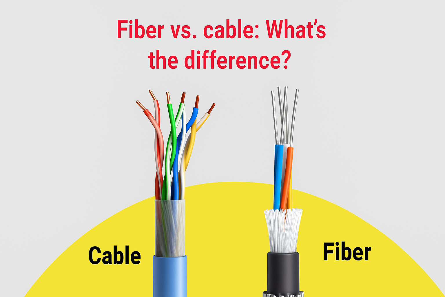
In today’s connected world, the speed of data defines productivity — from industrial automation to cloud computing, every second of latency can mean lost efficiency. Behind this digital speed race stand two giants of communication: fiber and cable. While both deliver internet connectivity, they do so using entirely different technologies — one through light and the other through electricity.
Fiber internet transmits data through glass fibers using light, offering higher speed, lower latency, and greater reliability than cable internet, which uses electrical signals over coaxial copper cables. Fiber is ideal for data-heavy, industrial, and long-distance communication, while cable remains cost-effective and widely available for moderate-use systems.
Imagine an engineering team designing a medical imaging system that streams real-time data. A few milliseconds of delay can distort results. Now imagine the same data carried through a fiber cable — light-fast, immune to interference, and secure. That’s the performance difference that defines the future of connectivity. In this guide, we’ll explore how fiber and cable differ, which one suits your OEM or engineering projects, and how Sino-conn can help you design the perfect custom fiber cable assembly for your application.
What Is Fiber Internet and How Does It Work?
Fiber internet is a broadband technology that transmits digital information as light pulses through thin strands of glass or plastic fibers. Unlike copper-based cables that rely on electrical signals, fiber uses optical transmission — allowing enormous amounts of data to move quickly and with minimal signal degradation. This makes it the most efficient medium for high-speed communication across industries such as telecommunications, automation, medical systems, and data centers.

How Fiber Transmission Works
In a fiber optic system, data is converted into light signals by lasers or LEDs at one end of the cable. These light pulses travel through the core of the fiber — a transparent medium only a few micrometers thick — while being reflected internally by a cladding layer that keeps the light contained within the core through a process called total internal reflection.
At the receiving end, a photodetector or optical transceiver converts these light pulses back into electrical signals that can be processed by electronic equipment.
This optical transmission method provides several fundamental advantages:
- Extremely high bandwidth capacity, supporting data rates in the gigabit and even terabit range.
- Low signal loss over long distances — typically less than 0.2 dB/km for modern single-mode fibers.
- Resistance to electromagnetic interference (EMI) and radio frequency interference (RFI), ensuring clean signal integrity in electrically noisy environments.
- Lightweight and compact design, enabling easier routing through tight spaces in industrial or telecom installations.
Structure of a Fiber Optic Cable

A typical fiber optic cable is made up of multiple layers designed to protect and stabilize the delicate fiber core:
- Core: The innermost layer, made of pure glass or plastic, through which light travels. The diameter of the core determines whether the cable is single-mode (SMF, 8–10 μm core) or multi-mode (MMF, 50–62.5 μm core).
- Cladding: A secondary glass layer that surrounds the core and maintains the reflection of light within it.
- Buffer Coating: A protective polymer layer that cushions the fiber from mechanical stress, bending, or abrasion.
- Strength Members: Kevlar or fiberglass reinforcements that add tensile strength and prevent stretching.
- Outer Jacket: The durable external sheath, often made from materials like PVC, LSZH, or TPU, which provides protection against moisture, oil, UV radiation, and temperature fluctuations.
Each layer can be customized according to the application — for example, tight-buffered designs for indoor installations, or loose-tube types for outdoor or high-temperature environments.
Types of Fiber Used in Communication
Fiber networks generally employ two main types:
- Single-Mode Fiber (SMF): Designed for long-distance, high-capacity transmission. The small core allows only one path for light to travel, minimizing attenuation and dispersion. Commonly used in telecom backbones, 5G infrastructure, and data centers.
- Multi-Mode Fiber (MMF): Features a larger core, allowing multiple light modes to propagate simultaneously. MMF is more suitable for shorter distances — typically up to 2 km — such as in LANs, medical devices, or industrial control systems.
Key Technical Parameters
| Parameter | Typical Range | Description |
|---|---|---|
| Core Diameter | 9 µm (SMF) / 50–62.5 µm (MMF) | Determines light path and bandwidth capacity |
| Wavelength | 850, 1310, 1550 nm | Operating light frequencies for different distances |
| Attenuation (Loss) | 0.2–3 dB/km | Signal loss per kilometer |
| Bandwidth Capacity | Up to 10+ Gbps | Speed potential for high-volume data |
| Operating Temperature | -40°C to +85°C | Ensures performance in industrial settings |
| Bend Radius | <30 mm typical | Indicates flexibility and mechanical endurance |
These parameters vary depending on whether the fiber is intended for indoor use, outdoor rugged applications, or high-temperature environments. For instance, fibers with low-smoke, halogen-free jackets are preferred in medical or aerospace applications for safety compliance.
Why Fiber Is More Efficient
From a physical standpoint, fiber’s efficiency stems from the nature of light transmission itself.
- No electrical resistance: There’s no current flow, so there’s no heat generation or signal distortion from resistance.
- Minimal crosstalk: Optical signals don’t interfere with each other, even in densely packed cable routes.
- Greater signal distance: A single fiber strand can maintain data integrity over tens of kilometers without amplification, compared to a few hundred meters for copper.
- Security: Light signals are extremely difficult to tap without detection, making fiber inherently more secure for sensitive data transfer.
Applications Across Industries
Fiber optic technology plays a foundational role in many modern systems:
- Telecommunication networks: Long-haul internet backbones and 5G transmission.
- Medical imaging: Fast, precise data transfer in MRI, CT, and endoscopic systems.

- Industrial control systems: EMI-free communication between sensors, PLCs, and control units.
- Broadcast and media: High-resolution video signal transmission.
- Data centers and AI computing: Reliable, high-speed interconnections for massive data workloads.
In essence, fiber internet represents a major evolution from traditional electrical transmission.
By using light instead of electrons, fiber systems achieve faster speeds, longer reach, and higher data capacity, all with reduced interference and maintenance.
For engineers and OEM developers, understanding how fiber works at the structural and optical level is key to selecting — or designing — the right cable configuration for each project’s performance, safety, and compliance requirements.
What Is Cable Internet and How Does It Work?
Cable internet uses coaxial cables with copper conductors to transmit electrical signals. It’s based on DOCSIS technology and offers affordable, widely available broadband speeds up to 1–2 Gbps, though it’s more prone to interference and slower uploads than fiber.
Cable internet is a mature technology still used in millions of homes and industrial facilities. It uses coaxial cables, which consist of a central copper wire surrounded by insulation, shielding, and a protective jacket.
What Are Coaxial Cables and How Do They Transmit Data?
Coaxial cables carry radio frequency (RF) signals through the central conductor. The surrounding shield minimizes signal leakage and interference. Data is transmitted as alternating electrical currents rather than light, making them cost-effective but bandwidth-limited.
What Are Common Coax Standards (RG, LMR, DOCSIS)?
- RG-Series: Legacy types like RG-6 or RG-59, common in TV networks.
- LMR Cables: Low-loss variants used for RF and telecom equipment.
- DOCSIS 3.1 & 4.0: Standards enabling gigabit speeds for broadband.
While performance improves with DOCSIS upgrades, copper’s electrical nature limits overall bandwidth compared to optical systems.
When Do OEMs Still Choose Cable Over Fiber?
OEMs and system integrators may still prefer coax when:
- The application covers short distances (<100 m).
- Legacy equipment uses coaxial connectors.
- The environment requires rugged, cost-sensitive solutions.
Sino-conn offers custom coaxial cable assemblies alongside fiber solutions, giving clients flexible connectivity options under one supplier.
How Do Fiber and Cable Internet Compare in Performance?
Fiber internet outperforms cable in speed, latency, reliability, and scalability. Cable is cheaper and more available, but fiber offers symmetrical upload/download speeds, no interference, and better future-proofing for industrial and data-heavy applications.
Here’s a direct comparison between fiber and cable technologies:
| Feature | Fiber Internet | Cable Internet |
|---|---|---|
| Transmission Medium | Light via glass fiber | Electrical via copper |
| Speed | Up to 10 Gbps+ | Up to 1–2 Gbps |
| Upload Speed | Equal to download | Slower |
| Latency | 1–5 ms | 10–30 ms |
| EMI Resistance | Excellent | Moderate |
| Distance Limit | >20 km | <100 m |
| Maintenance | Low | Moderate |
| Scalability | High | Limited |
| Installation Cost | Higher upfront | Lower |
| Ideal Use | Industrial / OEM / Data center | Consumer / Legacy systems |
Fiber’s symmetrical bandwidth and immunity to electromagnetic interference make it ideal for factory automation, 5G backhaul, and medical data transmission — where accuracy and uptime are critical.

Which One Is Better for Different Applications?
Fiber is best for high-speed, interference-free communication in industrial, medical, and telecom applications. Cable remains practical for short-range, budget-sensitive, or legacy systems still relying on coaxial connections.
Industrial Automation
Factories rely on real-time control networks. Fiber ensures consistent communication across PLCs and sensors without EMI disturbance from heavy machinery.
Medical Equipment
MRI and imaging devices require low-noise, high-precision data transfer. Fiber’s dielectric nature eliminates electrical shock risk and ensures sterile, interference-free operation.
Telecom and Data Centers
Fiber backbones power 5G, cloud, and IoT. Multi-mode or single-mode fibers are used depending on transmission range.
Consumer and Legacy Systems
Cable internet remains sufficient for moderate home or office use, offering gigabit speeds without major infrastructure investment.
OEM Integration
Many OEMs adopt hybrid systems — fiber for backbone communication and coax for device-level connections. Sino-conn supports both with customized assemblies tailored to signal, connector, and environmental requirements.
Do Fiber Cables Require Custom Design or Assembly?
Yes. In many industrial, telecom, and medical applications, fiber cables must be custom-designed and assembled to ensure precise compatibility, environmental durability, and optimal optical performance. Unlike generic patch cords used in office or home networks, OEM systems often involve complex integration — where every parameter, from connector type to jacket material, affects the reliability and signal quality of the entire system.
Why Customization Is Necessary
Fiber assemblies are not one-size-fits-all. The optical, mechanical, and environmental requirements vary dramatically between applications such as:
- Medical devices that must endure sterilization and bending.
- Industrial robots that require flexible, oil-resistant cables.
- Outdoor telecom systems exposed to UV, moisture, and temperature extremes.
Each of these use cases demands a unique combination of optical characteristics and mechanical protection. For instance:
- Single-mode fibers are needed for long-distance, low-loss links.
- Multi-mode fibers may suffice for shorter, high-density connections.
- Armored designs protect fibers from crushing or rodent damage in field installations.
A well-engineered assembly ensures signal integrity, mechanical resilience, and certification compliance, all of which are critical in OEM system design.
Key Design Factors in Custom Fiber Assemblies
Custom fiber cable design involves multiple interdependent variables. Engineers typically evaluate the following:
| Design Aspect | Options / Parameters | Engineering Considerations |
|---|---|---|
| Fiber Type | Single-mode (OS1/OS2) / Multi-mode (OM1–OM5) | Determines speed, range, and bandwidth |
| Connector Type | SC, LC, FC, ST, MPO/MTP | Must match transceivers or panel interfaces |
| Cable Structure | Tight-buffered, loose-tube, breakout, or armored | Balances flexibility, strength, and environmental resistance |
| Jacket Material | PVC, LSZH, TPU, PUR | Selected for flame, oil, UV, or chemical resistance |
| Length & Polarity | Defined per layout and data direction | Ensures proper signal routing and installation ease |
| Optical Performance | Insertion loss, return loss | Tested and verified to maintain transmission quality |
These design variables are adjusted according to both the application environment (indoor/outdoor, cleanroom, factory floor, vehicle interior) and the mechanical integration (connector type, bend radius, and routing path).
The Engineering Process of Fiber Cable Assembly
A custom fiber assembly typically follows a defined engineering workflow to ensure both technical accuracy and manufacturability:
- Requirement Analysis – The client or engineer provides system parameters: length, connector type, transmission distance, and operating conditions. Sometimes only a photo or a reference sample is provided.
- Cable Selection & Design – The engineering team selects fiber types, connectors, and jackets according to the optical and mechanical requirements.
- CAD Drawing Development – A detailed drawing is created, including pin definitions, connector orientation, and tolerances. CAD files are usually converted to PDF for client confirmation.
- Sample Prototyping – A functional sample is produced for validation, with typical lead times of a few days for urgent projects.
- Testing & Qualification – Each assembly undergoes optical testing (insertion loss, return loss), mechanical inspection, and environmental stress checks.
- Mass Production – Once approved, production follows controlled processes with traceability of materials and parameters.
- Final Quality Inspection – 100% inspection ensures conformance before shipment, including both visual and performance verification.
This structured process minimizes errors, ensures consistency, and shortens the time between prototype approval and large-scale production.
Testing and Quality Control
Custom fiber assemblies must meet precise optical performance metrics. The most common include:
| Test Item | Standard Value | Purpose |
|---|---|---|
| Insertion Loss | <0.3 dB (typical) | Measures signal attenuation through connectors |
| Return Loss | >50 dB | Ensures minimal reflection at connection points |
| Fiber Geometry | ±1 μm core concentricity | Guarantees alignment accuracy |
| Polish Type | UPC / APC | Affects back reflection and signal stability |
| Environmental Endurance | Thermal cycling, humidity | Verifies resistance to field conditions |
Mechanical tests — such as tensile, bend, and impact testing — are also performed, especially for assemblies used in rugged or high-vibration environments.
Compliance and Standards
Professional-grade fiber assemblies are designed to comply with multiple international standards:
- UL (Safety and flammability)
- RoHS / REACH (Material safety and environmental compliance)
- ISO 9001 / 14001 (Manufacturing quality and process control)
- IEC / TIA / EIA (Optical performance standards)
In some industries — such as medical or defense — additional certifications or documentation may be required, such as COC (Certificate of Conformance) or COO (Certificate of Origin). These certifications ensure traceability and global compliance.
Integration with OEM Systems
For OEM engineers, the cable is not just a passive link — it’s an integrated part of the system’s signal chain. A mismatch in impedance, fiber type, or connector geometry can lead to performance degradation, reflection, or incompatibility with transceivers.
Therefore, close coordination between the cable supplier and the OEM’s design team is essential. Through shared drawings and performance reports, the cable can be optimized to meet the exact system-level performance expectations — whether for medical diagnostic instruments, optical sensors, or 5G network devices.
In conclusion, custom design and assembly are often essential for fiber cables used in professional and industrial environments. The customization ensures that:
- The optical parameters match system bandwidth and distance.
- The mechanical build fits specific installation or motion requirements.
- The materials comply with relevant safety and environmental standards.
- The assembly is tested and documented to ensure repeatable, long-term reliability.
Custom fiber assemblies transform optical technology from a generic communication medium into an application-specific engineered component, ensuring that performance, safety, and reliability remain consistent throughout the life of the system.

Is Fiber Internet the Future?
Yes. With 5G, AI, and cloud computing demanding high bandwidth and low latency, fiber internet is the backbone of future communication. Custom fiber assemblies enable OEMs to meet next-generation performance needs.
Global data traffic doubles every two years. Fiber’s scalability makes it the only medium capable of sustaining exponential growth. According to the FTTH Council, fiber coverage continues to expand globally at a rapid pace, driven by 5G backhaul, cloud and AI workloads, with hybrid fiber systems bridging remote areas.
As industries digitize — from smart manufacturing to autonomous vehicles — custom fiber assemblies will form the nervous system of global connectivity.
Conclusion
For high-bandwidth, low-latency and EMI-sensitive scenarios, fiber is typically the preferred choice for speed, reliability, and scalability. Yet, the right solution isn’t just about choosing fiber — it’s about engineering the cable that fits your unique environment. That’s where Sino-conn excels.
Whether you need a custom fiber optic cable assembly for a medical device, telecom system, or industrial network, Sino-conn offers:
- Rapid prototyping (3 days)
- No MOQ
- Global certifications (UL, ISO, RoHS, REACH)
- Professional engineering support
Contact Sino-conn today to discuss your next custom fiber cable project — and bring precision, performance, and reliability to your connectivity design.


