 Skip to content
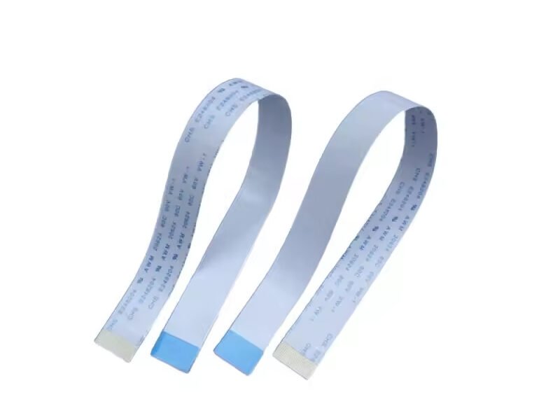
In nearly every modern electronic device — from smartphones and laptops to industrial robots and automotive dashboards — there’s a silent hero enabling high-density, reliable interconnection: the Flexible Flat Cable (FFC). FFCs are the thin, bendable ribbons that carry signals between components where space is limited and precision is key. Yet despite their ubiquity, many designers and buyers still ask the same fundamental question: What exactly is FFC, and how does it differ from other cable types like FPC or ribbon wire?
An FFC (Flexible Flat Cable) is a flat, lightweight electrical cable made of multiple parallel conductors laminated between flexible insulation films. It’s designed for compact, high-density connections in devices such as laptops, displays, printers, and automotive systems.
Understanding FFCs isn’t just a matter of definitions — it’s essential for selecting the right interconnect for your project’s electrical, mechanical, and thermal needs. In this guide, we’ll explore what FFC stands for, how it’s made, its advantages and disadvantages, key specifications, and how Sino-Conn helps global clients design and customize their ideal flat-cable solutions.
What Is an FFC Cable and How Does It Work?
An FFC cable, short for Flexible Flat Cable, is a type of electrical interconnect that uses multiple thin, flat copper conductors arranged side by side and encapsulated within a flexible plastic film. Unlike traditional round cables, which twist multiple insulated wires into a bundle, FFCs are completely flat — resulting in a compact, lightweight, and highly bendable assembly that fits perfectly into confined or moving applications such as printers, laptops, cameras, and automotive displays.
What Does FFC Stand For?
The acronym FFC stands for Flexible Flat Cable — a name that captures its two defining characteristics:
- Flexible: Capable of bending, folding, or twisting without compromising electrical continuity.
- Flat: The conductors are arranged in a single plane, allowing uniform thickness and consistent spacing.
The design eliminates the irregular geometry found in round wires, which can introduce impedance variation and signal interference. The term FFC often appears in conjunction with FPC (Flexible Printed Circuit), though the two have distinct structures and manufacturing methods — a topic explored in a later section.
Basic Structure and Function
To understand how an FFC cable works, it helps to visualize its multi-layer composition.
| Layer | Typical Material | Purpose / Function |
|---|---|---|
| Conductor | Bare or tinned copper | Carries electrical current or signal |
| Base Insulation Film | PET (polyester) or PI (polyimide) | Electrically isolates conductors |
| Adhesive Layer | Heat-resistant epoxy | Bonds the conductor and insulation film |
| Cover Layer (Top Film) | PET or PI | Provides mechanical protection |
| Stiffener (optional) | Polyester or FR-4 | Adds rigidity at the termination area |
The copper conductors are laid out parallel to each other, maintaining precise spacing — called the pitch — which defines how the FFC interfaces with its mating connector. Once laminated, the cable remains thin (often less than 0.5 mm) and highly flexible.
How It Works:
Electrical signals or power flow along the flat copper conductors, while the insulation film prevents short circuits and provides mechanical strength. The uniform geometry ensures predictable impedance, which is critical for signal integrity in high-speed applications such as LVDS display interfaces or USB 3.0 data links.
Because FFCs are planar, their electrical path lengths are equal, minimizing timing skew and maintaining synchronization between parallel signals — a key advantage over round multi-core cables.
Signal Transmission and Mechanical Behavior
When an FFC is bent, its outer surface stretches while the inner surface compresses. The conductors are designed to tolerate this stress by balancing conductor thickness and bend radius.
A thinner copper foil (e.g., 0.05 mm) allows tighter bending but reduces current capacity. Engineers typically follow these parameters:
| Pitch (mm) | Copper Thickness (mm) | Minimum Bend Radius |
|---|---|---|
| 0.3 – 0.5 | 0.03 – 0.05 | 2–3 mm |
| 1.0 | 0.08 | 5–8 mm |
| 2.54 | 0.1 – 0.15 | 10–15 mm |
This flexibility enables the FFC to connect moving or hinged parts — for example, the hinge between a laptop keyboard and display — while maintaining signal reliability through thousands of cycles.
Common Materials and Their Roles
- Copper (Conductor): Offers excellent electrical conductivity and low resistance. Depending on cost and application, it can be bare, tinned, or silver-plated to improve corrosion resistance and solderability.
- PET (Polyethylene Terephthalate): The most common insulation film for general-purpose FFCs. It’s affordable, lightweight, and has sufficient flexibility for consumer electronics. Temperature rating: typically –20 °C to +80 °C.
- Polyimide (PI): Used in high-temperature or high-flex applications such as automotive interiors and robotics. It withstands continuous operation at up to 150 °C and offers superior mechanical endurance.
- Adhesive Layers: Epoxy or acrylic adhesives bond copper and film during lamination. The adhesive must tolerate heat during reflow or soldering while maintaining flexibility.
- Stiffeners (Optional): Added at the connector termination to make insertion into ZIF (Zero Insertion Force) connectors easier and to prevent bending stress near the contact area.
Why FFCs Are Preferred in Modern Designs
Compared to round cables or discrete wires, FFCs provide several engineering advantages:
- Space Efficiency: Flat geometry saves vertical and horizontal space.
- Weight Reduction: Ideal for portable or wearable devices.
- Ease of Assembly: Pre-terminated ends simplify connector mating.
- Consistent Impedance: Beneficial for high-speed differential pairs.
- Reduced Crosstalk: Uniform spacing minimizes electromagnetic coupling.
- Aesthetic Integration: Their low-profile design supports sleek consumer devices.
Example:
In a laptop, a single FFC can replace multiple wire harnesses — connecting the mainboard to the display, keyboard, and touchpad. This reduces internal clutter and improves cooling airflow.
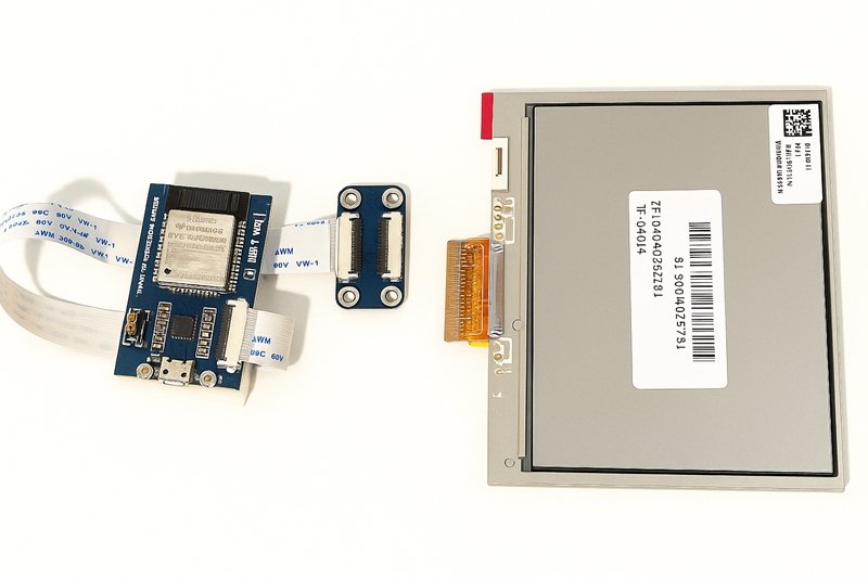
Application Case Study: From Concept to Custom FFC
A recent Sino-Conn project involved designing a 0.5 mm pitch 30-pin FFC for an automotive infotainment screen.
The challenge: achieve stable signal transmission under constant vibration and 90 °C ambient temperature.
Solution:
- Switched from PET to polyimide film for high-temperature resistance.
- Added aluminum foil shielding to mitigate EMI.
- Reinforced both ends with FR-4 stiffeners to prevent micro-cracks.
- Conducted 100% continuity and bend tests for validation.
The result was a fully customized, tested FFC cable delivered with a 3-week lead time, meeting OEM reliability and cost expectations — a demonstration of how flexible flat cables can be adapted to exact client needs.
Advantages at a Glance
| Parameter | FFC Cables | Traditional Round Wires |
|---|---|---|
| Flexibility | Excellent | Moderate |
| Thickness | < 0.5 mm | > 2 mm |
| Signal Integrity | High, consistent impedance | Variable |
| Assembly Time | Short | Long (manual wiring) |
| EMI Performance | Low crosstalk | Moderate |
| Cost | Moderate | Moderate–High |
What Are the Main Types of FFC Cables?
The main types of FFC cables include single-sided, double-sided, shielded, and ZIF-compatible designs. Each type varies by conductor layout, insulation film, and connector interface, allowing engineers to match flexibility, EMI performance, and pitch to their system’s electrical and mechanical requirements.
Single-Sided vs.Double-Sided FFC Cables
The simplest way to classify FFC cables is by how their conductors are exposed at each end.
Single-Sided FFC (Type A or Type B)

A single-sided FFC has its copper conductors exposed on one side only, meaning both cable ends align in the same orientation.
- Type A: Exposed contacts on the same side at both ends.
- Type B: Exposed contacts on opposite sides.
These are the most common FFCs used in consumer electronics — for example, connecting the display panel to the mainboard in a laptop or camera. The simplicity of the design makes them affordable and easy to terminate.
Double-Sided FFC (Type C)
A double-sided version has exposed copper conductors on both surfaces, allowing for reverse-mating flexibility and more complex routing in tight assemblies.
They are often used where the FFC must twist or fold multiple times — such as in foldable devices, printers, or industrial automation equipment where dynamic bending occurs.
| Type | Exposed Contact Orientation | Flexibility | Typical Application |
|---|---|---|---|
| Type A | Same side both ends | Standard | Laptop keyboard-to-board connection |
| Type B | Opposite sides | High | TV display, camera sensor |
| Type C | Both sides | Very High | Robotics, moving modules |
Shielded and Unshielded FFC Cables
The next major distinction involves electromagnetic shielding. Shielding improves performance in environments with strong electrical noise or high-frequency signals.
Unshielded FFC
Unshielded types are lightweight and economical, suitable for low-frequency or digital signals where EMI (electromagnetic interference) isn’t a concern. They are commonly found in consumer devices, 3D printers, and low-speed signal lines.
Shielded FFC
In a shielded FFC, a conductive foil or braid (usually aluminum or copper) is added over or between insulation layers. The shield layer reflects or absorbs external electromagnetic fields, protecting the internal signal lines.
Some advanced versions use drain wires connected to ground, improving EMI suppression and ESD resistance. Shielded FFCs are typically used in automotive, industrial, and telecom equipment.
| Parameter | Unshielded FFC | Shielded FFC |
|---|---|---|
| EMI Resistance | Basic | Excellent |
| Thickness | Thinner | Slightly thicker |
| Weight | Lighter | Heavier |
| Cost | Lower | Higher |
| Typical Use | Consumer electronics | Automotive, industrial systems |
Example:
In a vehicle infotainment system, Sino-Conn developed a shielded 40-pin 0.5 mm pitch FFC using copper foil and polyimide film. It reduced EMI by 70% compared with the previous unshielded design while maintaining the same flexibility and pitch tolerance.
ZIF (Zero Insertion Force) and Non-ZIF Compatible FFCs
One of the most defining features of FFC cables is how they interface with connectors.
ZIF-Compatible FFC
ZIF (Zero Insertion Force) connectors are the industry standard for delicate, fine-pitch cables. They allow the cable to slide into the connector with virtually no mechanical force; a locking flap then secures it. This reduces stress on the cable, extending its lifespan.
ZIF-compatible FFCs are often reinforced with stiffeners — thin PET or FR-4 pieces at the ends — to aid insertion and ensure consistent contact pressure.
Advantages:
- Prevents tearing or damage during assembly
- Ideal for fine-pitch (<0.5 mm) designs
- Common in laptops, LCDs, and mobile devices
Non-ZIF (Friction-Lock) FFC
Non-ZIF versions rely on friction or mechanical clips for contact retention. They are simpler and lower-cost but require greater insertion force and can wear out over time in frequent plug/unplug situations.
Common Use Cases:
- LED modules
- Office printers
- Test fixtures and internal prototyping setups
What Is the Difference Between FFC and FPC?
Many people use FFC and FPC interchangeably, but they refer to two different technologies — one cable-based, one circuit-based.
| Feature | FFC (Flexible Flat Cable) | FPC (Flexible Printed Circuit) |
|---|---|---|
| Structure | Laminated copper conductors in parallel | Etched copper traces on flexible substrate |
| Flexibility | Excellent | Exceptional (can fold in multiple axes) |
| Cost | Lower | Higher |
| Customization | Limited to pitch, length, termination | Fully customizable trace routing |
| Applications | Interconnect between boards | Integrated circuits, flex PCB assemblies |
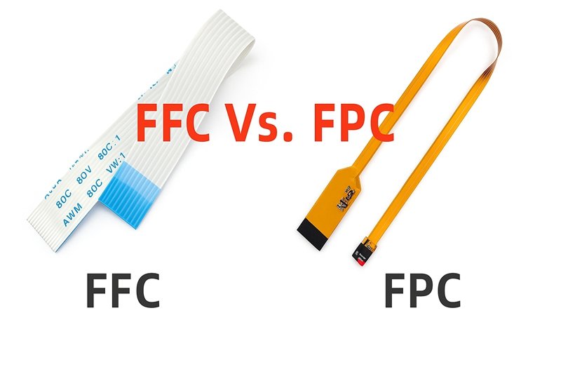
FFC is a ready-to-use interconnect cable for board-to-board or module-to-board connections.
FPC, on the other hand, acts as an integrated circuit substrate, allowing for more complex routing but at a higher cost.
Example:
A laptop screen typically uses an FFC to connect the display to the logic board.
However, inside the display itself, an FPC connects the driver ICs and backlight circuits.
Specialized Variants and Emerging FFC Technologies
- High-Temperature FFCs: Built with polyimide film, capable of operating continuously at 125–150 °C, used in automotive and aerospace.
- Reverse-Bend or Foldable FFCs: Designed to endure repeated folding cycles in compact hinge mechanisms (e.g., foldable tablets).
- Stiffened Ultra-Fine Pitch FFCs: Pitch <0.3 mm for high-speed signals like LVDS, HDMI, or USB 3.1 interfaces. Often paired with micro-ZIF connectors.
- Hybrid Power-Signal FFCs: Combine thicker outer conductors for power with thinner inner lines for data transmission, used in modern IoT modules and embedded systems.
Choosing the Right Type
When deciding between types, consider these core parameters:
| Design Factor | Recommended Type | Reason |
|---|---|---|
| Limited space, low current | Unshielded single-sided | Thinnest, lowest cost |
| EMI-sensitive, automotive | Shielded | Superior interference resistance |
| Frequent plug/unplug | ZIF-compatible | Prevents wear and tear |
| High data rate (>1 Gbps) | Fine-pitch shielded | Stable impedance |
| Foldable or moving assembly | Double-sided or PI-based | Long flex life |
How Are FFC Cables Manufactured?
FFC cables are made by laminating flat copper conductors between flexible plastic films such as PET or polyimide under heat and pressure. The process includes conductor preparation, alignment, insulation bonding, cutting, stiffener application, and electrical testing. Precision in pitch control and material bonding ensures signal integrity, flexibility, and long-term reliability in compact electronic systems.

1. Conductor Preparation
The process begins with copper, the conductive medium responsible for transmitting electrical signals or power.
Material Selection
- Copper Type: High-purity electrolytic copper (99.97% Cu) is used for optimal conductivity.
- Surface Finish: Conductors may be bare, tinned, or silver-plated depending on corrosion resistance or soldering needs.
- Thickness Range: 0.03 mm to 0.15 mm, balancing flexibility and current capacity.
Conductor Forming Methods
There are two main production techniques used to create the conductive layer in FFCs:
| Method | Description | Advantages | Typical Use |
|---|---|---|---|
| Laminated Wire Type | Flat copper wires are laid in parallel and bonded between films. | Low tooling cost, ideal for small runs. | Consumer electronics, prototypes. |
| Etched Type | Copper foil is etched photochemically into conductor patterns on a base film. | High precision, tight pitch (<0.3 mm). | Automotive, medical, and high-density electronics. |
Sino-Conn typically uses laminated-type manufacturing for standard and custom orders, as it offers faster lead times (2–3 days for samples) and allows easy adjustment of pitch, width, and conductor count.
2. Conductor Alignment and Pitch Control
Accurate pitch spacing — the distance between conductor centers — is fundamental to FFC performance.
- Common Pitch Values: 0.3 mm, 0.5 mm, 0.8 mm, 1.0 mm, 2.54 mm.
- Tolerance: ±0.03 mm for high-precision assemblies.
Conductors are positioned using CNC alignment jigs or automated feeding rollers. Any deviation can cause poor connector fit or inconsistent impedance.
For fine-pitch cables, optical alignment cameras ensure every conductor remains perfectly parallel during lamination.
Design Tip:
A smaller pitch increases data density but also raises the risk of crosstalk. Engineers often balance electrical and mechanical requirements by combining fine-pitch inner signal lines and wider outer power lines within the same FFC.
3. Insulation Film Lamination
Once conductors are aligned, they are sandwiched between two thin films of insulation material — typically PET (polyester) for general-purpose FFCs, or PI (polyimide) for high-temperature or flexible designs.
Film Characteristics
| Film Type | Operating Temp. | Flexibility | Cost Level | Typical Application |
|---|---|---|---|---|
| PET | –20°C to +80°C | Good | Low | Consumer electronics, displays |
| Polyimide (PI) | –40°C to +150°C | Excellent | Medium–High | Automotive, industrial, robotics |
| PEN | –30°C to +120°C | Moderate | Medium | LED lighting, smart devices |
The lamination process applies heat (150–250°C) and pressure (0.2–0.5 MPa) through a precision roller press.
Special heat-resistant adhesives (epoxy, acrylic, or polyamide-imide) bond the conductor and insulation film while maintaining flexibility.
During this step, air bubbles or uneven bonding can cause insulation voids, leading to potential dielectric breakdown. Sino-Conn employs vacuum lamination and continuous inspection to guarantee consistent film adhesion and cable thickness (typically 0.2–0.5 mm).
4. Cutting, Punching, and Stiffener Application
After lamination, the continuous sheet of FFC material is processed into individual cables through CNC cutting or die stamping.
Precision Cutting
- Length tolerance is controlled to ±0.5 mm.
- Edge trimming ensures smooth sides and proper width for connector mating.
End Preparation
Each cable end is stripped or exposed to create contact areas that align with the intended connector (ZIF or non-ZIF).
For ZIF-compatible cables, a reinforcement stiffener — typically PET or FR-4 — is added at the termination area. This prevents bending near the connector interface, maintaining consistent contact pressure.
| Stiffener Material | Function | Common Use |
|---|---|---|
| PET | Adds moderate stiffness, low cost | Consumer electronics |
| FR-4 | Adds rigidity and dimensional stability | Industrial or automotive FFCs |
| Polyimide | Used in high-flex designs | Robotics or folding devices |
In some designs, solder tabs or crimp contacts are integrated for non-ZIF terminations. Sino-Conn can modify end configurations according to customer drawings or connector models.
5. Shielding (Optional)
To enhance electromagnetic compatibility (EMC), FFCs can be laminated with a shielding layer:
- Aluminum Foil: Lightweight and cost-effective.
- Copper Foil or Braiding: Superior shielding performance for high-frequency circuits.
- Conductive Adhesive + Drain Wire: Ensures grounding and consistent EMI suppression.
Shielded FFCs are essential for automotive displays, camera systems, and high-speed signal lines such as LVDS or HDMI. Sino-Conn can integrate these layers during lamination or as a post-processing step depending on design complexity.
6. Electrical and Mechanical Testing
Before shipping, every FFC cable undergoes 100% inspection to verify continuity, insulation integrity, and mechanical durability.
Typical Tests Include:
- Continuity Testing: Ensures no open or short circuits between conductors.
- Dielectric Withstand Test (Hi-Pot): Verifies insulation can resist specified voltage levels (commonly 300–500V).
- Resistance Measurement: Confirms conductor consistency along the entire length.
- Bending / Flex Test: Simulates repeated folding cycles (up to 10,000) for dynamic-use cables.
- Dimensional Verification: Optical inspection checks pitch, width, and cut accuracy.
Sino-Conn’s QC protocol follows ISO and UL standards, incorporating both in-process and final inspection stages — a triple-check system (during lamination, after cutting, and before packing).
7. Labeling, Packaging, and Traceability
After passing inspection, cables are individually labeled with part numbers, batch codes, and test identifiers for traceability.
Packaging Considerations:
- Anti-static bags prevent ESD damage.
- Moisture-absorbing packs are used for long-term storage.
- Reel or flat packaging ensures cables remain unbent during shipping.
What Are the Key Performance Specifications to Consider?
Key performance specifications for FFC cables include conductor pitch, current capacity, voltage rating, bend radius, impedance control, and temperature range. These parameters determine the cable’s flexibility, electrical integrity, and environmental durability. Understanding each factor helps engineers match FFC designs to mechanical space limits and signal performance requirements.
Conductor Pitch and Number of Conductors
The pitch is the center-to-center distance between adjacent conductors.
It determines how tightly signals can be routed and what connectors are compatible.
- Common Pitch Values: 0.3 mm, 0.5 mm, 0.8 mm, 1.0 mm, and 2.54 mm.
- Tolerance: ±0.03 mm to ±0.05 mm for fine-pitch assemblies.
- Conductor Count: From 4 pins up to 80 pins or more.
| Pitch (mm) | Typical Application | Advantages | Considerations |
|---|---|---|---|
| 2.54 mm | Industrial controllers | Robust, easy to handle | Bulky, lower density |
| 1.0 mm | Printers, scanners | Balance of cost & space | Moderate flexibility |
| 0.5 mm | Laptops, displays | Compact, supports ZIF connectors | Higher precision required |
| 0.3 mm | High-speed data lines | Very compact | Sensitive to handling & alignment |
Design Insight:
A smaller pitch enables more signal lines in less space — ideal for compact electronics — but requires tighter impedance control and high manufacturing precision. Sino-Conn uses optical alignment to maintain consistent pitch even in ultra-fine designs.
Current Capacity and Voltage Rating
Every conductor in an FFC has a maximum current-carrying capacity, influenced by its width, thickness, and material.
Typical Electrical Ratings:
| Conductor Width (mm) | Thickness (mm) | Max Current (A) | Typical Voltage Rating (V) |
|---|---|---|---|
| 0.3 | 0.035 | 0.3 – 0.5 | 30 – 60 V |
| 0.5 | 0.05 | 0.8 – 1.0 | 60 – 100 V |
| 1.0 | 0.08 | 1.5 – 2.0 | 100 – 150 V |
| 2.0 | 0.12 | 3.0 – 5.0 | 250 V + |
Key Factors Affecting Current Handling:
- Conductor width and copper thickness
- Operating temperature
- Ambient cooling and airflow
- Signal frequency (AC losses)
Engineering Note:
If higher current capacity is needed, Sino-Conn can customize by increasing conductor width or using thicker copper foil, while ensuring sufficient flexibility through material balancing.
Impedance and Signal Integrity
For high-speed signal lines (LVDS, HDMI, USB 3.x, etc.), maintaining consistent impedance is essential to prevent reflections or signal loss.
Typical Impedance Range:
- Single-ended lines: 50 – 60 Ω
- Differential pairs: 90 – 120 Ω
Factors influencing impedance include:
- Conductor spacing (pitch)
- Dielectric constant of insulation film (PET ≈ 3.3, PI ≈ 3.5)
- Conductor thickness
- Shielding and ground plane layout
Best Practice:
When precision impedance is required, Sino-Conn performs TDR (Time Domain Reflectometry) testing to confirm uniform transmission characteristics. Shielded FFCs with grounded drain wires help maintain low crosstalk and stable impedance across long runs.
Flexibility and Minimum Bend Radius
FFC cables are designed to bend repeatedly without fracturing or losing continuity.
The minimum bend radius (Rmin) is a key specification — it defines how tightly the cable can bend without mechanical or electrical failure.
| Cable Thickness (mm) | Typical Min. Bend Radius (mm) | Flex Cycles (Dynamic Use) |
|---|---|---|
| 0.2 | 3 – 5 | 10,000 + |
| 0.3 | 5 – 8 | 8,000 – 10,000 |
| 0.5 | 8 – 10 | 5,000 – 8,000 |
| 0.8 | 12 – 15 | 3,000 – 5,000 |
Design Considerations:
- Avoid sharp 90° bends; use smooth curves.
- Position bends away from termination areas.
- For repetitive motion (e.g., printer heads, robotic joints), use polyimide-based FFCs with ultra-thin copper.
Sino-Conn Testing Insight:
Every dynamic-use FFC is tested under a bend-flex tester simulating real-world movement. Standard cables withstand 5,000 cycles; high-flex versions exceed 10,000 cycles without conductor fatigue.
Temperature Range and Environmental Resistance
Operating temperature affects both electrical resistance and mechanical stability.
Choosing the right insulation material ensures the FFC performs reliably across various environments.
| Material | Temperature Range (°C) | Resistance Properties | Use Case |
|---|---|---|---|
| PET | –20 ~ +80 | Basic heat resistance | Office equipment, displays |
| PEN | –30 ~ +120 | Moderate | Lighting, smart appliances |
| PI (Polyimide) | –40 ~ +150 | Excellent heat, oil, and UV resistance | Automotive, industrial |
| Halogen-Free PET | –20 ~ +105 | Eco-friendly, flame-retardant | Consumer electronics |
| PTFE | –60 ~ +200 | Extreme temperature stability | Aerospace, medical |
Environmental Resistance Parameters:
- Oil Resistance: Prevents chemical degradation in industrial use.
- UV Resistance: Ensures outdoor performance.
- Flame Retardancy: UL VW-1 or UL94 V-0 ratings available.
- Moisture Resistance: Maintains insulation even in humid conditions.
Sino-Conn supplies FFCs compliant with UL, ROHS, REACH, and PFAS-free standards for eco-sensitive markets.
Mechanical Strength and Durability
Beyond flexibility, cables must endure tension, insertion, and vibration stresses.
| Parameter | Typical Range | Testing Standard |
|---|---|---|
| Tensile Strength | > 80 N/mm² | ASTM D882 |
| Peel Strength (Conductor – Film Bond) | ≥ 1.0 N/10 mm | IPC 620 Class 2 |
| Stiffener Adhesion | ≥ 0.8 N/10 mm | Internal QC |
| Insertion Force (ZIF Connector) | < 0.5 N | IEC 60352 |
Quality Tip:
Reinforcement stiffeners (PET or FR-4) can be added to both ends to improve connector handling and mechanical endurance — especially useful in vibration-prone automotive or industrial systems.
Shielding Effectiveness and EMI Control
In high-speed or noisy environments, EMI shielding ensures clean signal transmission.
Shielding Options:
- Aluminum Foil Laminate – lightweight, economical.
- Copper Foil Shielding – high conductivity, best EMI suppression.
- Ground Drain Wire – provides grounding path for shield.
- Conductive Adhesive – ensures continuous electrical contact.
Performance Benchmark:
- Attenuation: 20 – 40 dB reduction of EMI up to 1 GHz.
- Ground Resistance: < 0.05 Ω between shield and ground.
Application Examples:
- Automotive infotainment and camera systems
- High-speed data transfer lines (HDMI, MIPI, USB 3.0)
- Sensitive measurement equipment
Sino-Conn can integrate customized EMI shielding during lamination or as an outer wrap — depending on thickness and flexibility requirements.
Length, Connector Compatibility, and Custom Definitions
- Standard Lengths: 30 mm – 1000 mm.
- Connector Type: ZIF, LIF, or custom friction-lock connectors.
- Orientation Options: Type A (same-side contact), Type B (opposite-side), or Type C (double-sided).
Custom Definitions (Pin-Out):
Sino-Conn supports complete pin assignment and interconnect mapping, ensuring compatibility between modules. Engineers can specify:
- Contact side orientation
- Reverse or straight pin definitions
- Ground and power distribution layout
Drawing Support:
Every custom order includes a CAD-to-PDF drawing for confirmation before production. Revisions can be completed within 30 minutes to match prototype needs.
Compliance and Certification Standards
Ensuring compliance with international standards guarantees product safety and market acceptance.
| Certification | Purpose |
|---|---|
| UL (Underwriters Laboratories) | Verifies flame retardancy and dielectric safety. |
| ISO 9001 / ISO 14001 | Quality and environmental management systems. |
| RoHS & REACH | Restricts hazardous substances and chemicals. |
| COC / COO | Country and conformity documentation for global export. |
| PFAS-Free / Halogen-Free | Eco-compliance for EU and U.S. markets. |
Where Are FFC Cables Used Across Industries?
FFC cables are widely used in industries such as consumer electronics, automotive, medical, industrial automation, and aerospace. Their thin, flexible structure enables compact and reliable connections in displays, sensors, robotic joints, and control modules. Engineers select FFCs for applications requiring space savings, lightweight design, and high-speed signal transmission.
1. Consumer Electronics
In the consumer sector, FFC cables are almost invisible yet everywhere — connecting displays, sensors, and controllers in devices we use daily.
Common Applications
- Laptops and Tablets: Connect the display, touch panel, and keyboard to the motherboard.
- Smartphones: Link screen modules, cameras, and fingerprint sensors.
- Printers and Scanners: Allow moving print heads and image sensors to operate freely without wire fatigue.
- Gaming Consoles and Cameras: Transfer high-speed video and control signals in small spaces.
Why FFCs Excel Here:
- Ultra-thin profile (0.2–0.5 mm) saves internal space.
- Easy ZIF insertion simplifies mass production.
- Excellent flexibility for folding designs and hinge mechanisms.
- Low signal loss for high-speed data lines like LVDS or MIPI.
Example:
In a laptop hinge assembly, a standard 0.5 mm-pitch PET-based FFC endures thousands of open/close cycles without conductor fatigue — a cost-effective alternative to fine round wires. Sino-Conn often supplies such designs with stiffeners and custom length definitions for ODM notebook manufacturers.
2. Automotive and EV Systems
Modern vehicles depend on a growing number of electronic modules and displays, many of which operate in vibration-prone or temperature-extreme environments.
FFCs are used because they combine lightweight design, reliable signal integrity, and resistance to EMI.
Key Applications
- Infotainment Displays and Instrument Clusters – FFCs connect touch screens, driver displays, and control boards.
- ADAS & Camera Modules – High-speed shielded FFCs transmit video and control data from cameras and radar sensors.
- Seat Control and Lighting Systems – Provide compact connections for moving or foldable components.
- Battery Management Systems (BMS) – Carry sensor and communication signals across tight battery compartments.
| Automotive Function | Cable Type | Material / Feature | Temperature Rating |
|---|---|---|---|
| Display connection | Shielded 0.5 mm pitch FFC | Polyimide + copper foil shield | –40 °C to +125 °C |
| Rear camera module | Fine-pitch (0.3 mm) FFC | PI insulation, EMI foil | –30 °C to +100 °C |
| Seat control | Multi-fold FFC | PET insulation | –20 °C to +80 °C |
| BMS harness | Custom flat cable with thick copper | 2 A per line, high durability | –40 °C to +150 °C |
Sino-Conn’s Engineering Edge:
For automotive clients, Sino-Conn provides UL-certified, halogen-free, and PFAS-free materials, capable of enduring up to 10,000 flex cycles and meeting EMI standards for camera systems. Custom shielded and drain-wired FFCs ensure low interference even under high load.
3. Medical Equipment and Healthcare Devices
The medical field demands compact, sterilizable, and highly reliable interconnects — qualities that make FFCs ideal for diagnostic and portable instruments.

Applications
- Diagnostic Imaging (CT, MRI, Ultrasound) – Carry low-noise data from sensors to control units.
- Patient Monitoring Devices – Connect flexible sensors on wearable or bedside devices.
- Portable Analyzers and Test Kits – Enable compact internal wiring without sacrificing flexibility.
- Surgical Robotics and Endoscopy Equipment – Use ultra-fine-pitch FFCs to route signals through articulated arms.
Advantages in Medical Environments
- Smooth surface and minimal particle generation reduce contamination.
- FFCs can be encapsulated or PTFE-coated for chemical resistance.
- Low dielectric loss ensures precision in sensor readings.
- Halogen-free and ISO 13485-compatible manufacturing possible.
Example:
A European medical client required a 40-pin, 0.3 mm-pitch shielded FFC for a handheld diagnostic scanner. Sino-Conn used polyimide film for flexibility and silver-plated copper to improve signal stability. The design survived over 15,000 dynamic bends and maintained electrical continuity — surpassing IEC 60601 durability requirements.
4. Industrial Automation and Robotics
Factories and industrial systems depend on reliable interconnects that survive mechanical motion, vibration, and heat. FFCs are increasingly replacing bulky harnesses in automation and motion-control systems.

Applications
- Robotic Arms and CNC Machines: Flexible FFCs link sensors, encoders, and controllers in moving joints.
- PLC and Control Panels: Compact internal cabling for human-machine interface (HMI) modules.
- Smart Sensors and IoT Devices: Connect compact sensor boards in harsh environments.
- LED Lighting Systems: Distribute power and control signals across modular light panels.
| Parameter | Standard Harness | FFC Alternative |
|---|---|---|
| Flexibility | Moderate | Excellent (10,000+ cycles) |
| Space Efficiency | Bulky | Flat, low-profile |
| Assembly Cost | Higher | Lower (ZIF insertion) |
| EMI Shielding | Optional | Integrated foil layer |
| Maintenance | Periodic replacement | Long-term reliability |
Industry Insight:
Automation OEMs are shifting toward foldable and shielded FFCs with integrated stiffeners to handle repetitive movement. Sino-Conn’s custom process allows polyimide lamination and reinforced end stiffeners, extending service life in robotic applications by up to 40 %.
5. Aerospace, Defense, and High-Reliability Systems
Aerospace and defense electronics operate under extreme thermal and mechanical stress, where weight reduction and precision are critical.
FFCs serve as lightweight data interconnects in avionics and sensor systems.
Applications
- Flight Instrumentation Panels – Compact cabling behind cockpit controls.
- Satellite Modules and Sensors – Lightweight data transmission harnesses.
- Radar and Communication Units – Shielded FFCs maintain impedance stability for RF signals.
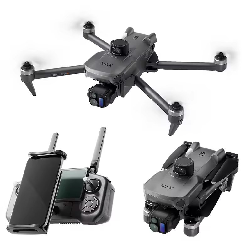
- Unmanned Systems (Drones, UAVs) – Connect cameras, GPS, and control electronics.
Advantages for Aerospace:
- Up to 70 % lighter than round cables.
- Withstand vibration and G-forces when properly stiffened.
- Operate across –55 °C to +200 °C with PTFE or PI insulation.
- Custom gold-plated copper conductors ensure corrosion resistance in high-altitude humidity.
Example:
A U.S. aerospace integrator partnered with Sino-Conn to develop a shielded PI-based FFC assembly for a drone navigation system. The cable weighed 45 % less than the previous wire harness and maintained < 2 % impedance deviation under vibration tests — critical for accurate signal timing.
6. Telecommunications and Networking
In networking devices, FFCs provide high-density, low-profile interconnections inside routers, switches, and communication base stations.
Applications
- 5G and LTE Modules: Connect transceiver boards with RF and control circuits.
- Network Routers and Servers: Enable compact board-to-board connections for signal distribution.
- Optical Transceivers and Data Storage Units: Transfer high-frequency data with stable impedance.
Why FFCs Are Preferred:
- Support high-speed differential signals (90 – 100 Ω impedance).
- Reduce internal EMI in densely packed enclosures.
- Improve airflow by eliminating bulky harnesses.
- Compatible with automated assembly lines via ZIF connectors.
Engineering Note:
For telecom customers, Sino-Conn provides TDR-tested, impedance-controlled FFCs using polyimide dielectric films and ground reference layers — ideal for consistent data throughput in 10 Gbps+ systems.
7. Emerging Technologies and Custom Integration
As devices continue shrinking and integrating more sensors, FFCs are expanding into wearables, IoT devices, and flexible electronics.
New Frontiers
- Wearable Health Monitors: Soft FFCs connect biometric sensors with mainboards.
- Smart Home Devices: Enable sleek, compact wiring for touch panels and smart hubs.
- Foldable Displays & AR/VR Headsets: Ultra-fine-pitch FFCs transfer data in tight hinge mechanisms.
- Solar Panels & Green Energy Modules: Flat cables route signals while minimizing shadowing.
FFC Applications by Industry
| Industry | Typical Use | Cable Features | Operating Conditions |
|---|---|---|---|
| Consumer Electronics | Displays, printers, mobile devices | PET insulation, 0.3–0.5 mm pitch | –20 °C ~ +80 °C |
| Automotive | Displays, sensors, BMS | Shielded PI, EMI foil | –40 °C ~ +150 °C |
| Medical | Diagnostics, patient monitors | Halogen-free, sterilizable | –40 °C ~ +125 °C |
| Industrial Automation | Robotics, HMI panels | Reinforced, high-flex | –30 °C ~ +120 °C |
| Aerospace | Avionics, UAVs | PTFE, lightweight | –55 °C ~ +200 °C |
| Telecom | 5G modules, routers | Impedance-controlled | –40 °C ~ +85 °C |
| IoT / Wearables | Sensors, smart home | Flexible PET/PI hybrid | –20 °C ~ +100 °C |
How to Choose the Right FFC Cable for Your Design
Selecting the correct Flexible Flat Cable (FFC) goes far beyond matching connector type or pin count. It’s about balancing electrical performance, mechanical flexibility, thermal endurance, and cost efficiency to fit the specific requirements of your system.
An improperly specified FFC can lead to issues such as signal distortion, connector misalignment, or premature failure due to mechanical fatigue.
1. Define the Electrical Requirements
The first step in FFC selection is understanding your electrical specifications, including voltage, current, impedance, and signal type.
Current and Voltage
Each conductor in an FFC can only handle a specific amount of current and voltage depending on its width, copper thickness, and insulation rating.
| Pitch (mm) | Conductor Width (mm) | Copper Thickness (mm) | Max Current (A) | Voltage Rating (V) |
|---|---|---|---|---|
| 0.3 | 0.10 | 0.03 | 0.3 – 0.5 | 30 – 50 |
| 0.5 | 0.20 | 0.05 | 0.8 – 1.0 | 50 – 100 |
| 1.0 | 0.40 | 0.08 | 1.5 – 2.0 | 100 – 150 |
| 2.54 | 1.00 | 0.12 | 3.0 – 5.0 | 250 + |
Guideline:
If your system drives power or LED circuits, select thicker copper (≥0.08 mm) for better current handling. For low-voltage signals, finer copper layers (0.03–0.05 mm) are ideal for flexibility.
Signal Type
- Low-frequency (DC / control): PET-based FFCs are sufficient.
- High-speed digital signals (HDMI, LVDS, USB): Shielded polyimide FFCs are recommended to minimize EMI and maintain impedance control.
Sino-Conn can perform TDR impedance testing for high-frequency lines to ensure consistent transmission between paired conductors.
2. Determine the Mechanical Design Parameters
The mechanical structure of your device — folding direction, hinge angle, and available routing space — strongly influences FFC selection.
Cable Length and Routing
FFC cables are available from 30 mm to 1,000 mm or more, with custom lengths easily produced.
Keep the routing path smooth — sharp bends can damage insulation or delaminate adhesive layers.
Bend Radius
The minimum bend radius is typically 10× the total cable thickness.
For example, a 0.3 mm-thick FFC should not bend tighter than a 3 mm radius.
Sino-Conn tests each cable type for flex cycles (up to 10,000+) to verify long-term durability in dynamic use cases.
Connector Orientation
Define whether the FFC will connect same-side (Type A) or opposite-side (Type B) contacts.
Engineers should verify connector locking type (ZIF, LIF, or friction) early in the design stage to prevent orientation errors.
3. Choose the Right Pitch and Conductor Count
The pitch (spacing between conductors) and number of pins determine both the data density and connector compatibility.
| Pitch | Signal Density | Typical Applications |
|---|---|---|
| 2.54 mm | Low | Industrial, control systems |
| 1.0 mm | Medium | Office electronics, printers |
| 0.5 mm | High | Laptops, displays |
| 0.3 mm | Ultra-high | Smartphones, automotive cameras |
Engineering Tip:
Smaller pitch improves space efficiency but increases sensitivity to tolerance errors. Sino-Conn maintains ±0.03 mm pitch precision using optical alignment for fine-pitch designs.
4. Select the Proper Insulation and Base Film
Different environments demand different insulation materials.
The choice between PET, PEN, PI, or PTFE determines heat resistance, flexibility, and chemical durability.
| Material | Operating Temp. (°C) | Key Strength | Best Use |
|---|---|---|---|
| PET | –20 ~ +80 | Economical, flexible | Consumer electronics |
| PEN | –30 ~ +120 | Moderate heat tolerance | Lighting, appliances |
| PI (Polyimide) | –40 ~ +150 | Excellent flexibility | Automotive, robotics |
| PTFE | –60 ~ +200 | Extreme thermal and chemical resistance | Aerospace, medical |
Design Note:
For devices that fold or operate in high-temperature environments, use polyimide-based FFCs.
PET types, while cost-effective, are better for static connections like display ribbons.
5. Evaluate Environmental and Reliability Requirements
FFC cables may face heat, humidity, vibration, or exposure to chemicals.
Matching the environmental class ensures reliability under these conditions.
Key Environmental Parameters
- Temperature: Confirm both operating and storage limits.
- Humidity: Select moisture-resistant adhesive systems for tropical climates.
- Vibration and Shock: Reinforced stiffeners protect termination points.
- Chemical Exposure: Polyimide or PTFE withstand oils and solvents.
| Environment | Recommended FFC Type | Protection Features |
|---|---|---|
| Office / Indoor | PET FFC | Basic insulation |
| Automotive Cabin | PI FFC | High-temp + EMI shield |
| Factory Floor | Reinforced PI | Oil & abrasion resistant |
| Outdoor / Marine | PTFE or coated PI | UV & corrosion resistant |
Sino-Conn’s automotive and industrial FFCs are tested for up to 150 °C, 10,000 bend cycles, and IEC 60352 vibration standards to guarantee endurance.
6. Consider Shielding and EMI Requirements
If your design handles high-speed or sensitive analog signals, shielding is crucial.
Unshielded FFCs may pick up electromagnetic noise, causing signal degradation.
Shielding Options
- Aluminum Foil Shield: Lightweight, economical.
- Copper Foil Shield: Better conductivity, robust EMI protection.
- Ground Drain Wire: Ensures continuous grounding between devices.
- Conductive Adhesive Layer: Provides uniform surface shielding.
Performance Advantage:
A shielded FFC can reduce EMI by 20–40 dB up to 1 GHz.
For automotive displays and camera systems, Sino-Conn offers shielded differential FFCs maintaining 90–110 Ω impedance.
7. Align Connector Compatibility and End Configuration
Connector Matching
Most FFCs interface with ZIF (Zero Insertion Force) or LIF (Low Insertion Force) connectors.
Ensure:
- The contact side (up or down) matches your connector type.
- The locking mechanism (slide, flip, or latch) aligns with the connector’s footprint.
- Pitch and pin count correspond precisely to your connector series.
End Reinforcement
Add PET or FR-4 stiffeners at terminations to improve insertion durability.
Sino-Conn also offers dual-sided and staggered-end options for special routing.
Custom Pin Definitions
Engineers can specify signal mapping (GND–VCC–DATA–CLK, etc.) for exact system integration. Sino-Conn provides CAD-verified pinout drawings before manufacturing.
Conclusion

Your Partner in Reliable Connectivity
From concept to production, Sino-Conn bridges the gap between design flexibility and manufacturing precision. Our custom FFC solutions power everything from automotive camera systems and medical diagnostics to industrial robots and foldable electronics.
If you’re developing the next generation of compact or high-performance electronics, Sino-Conn is ready to design, prototype, and manufacture your flexible flat cable assembly — exactly to your specifications.
Contact us today to discuss your design or request a drawing.


