 Skip to content
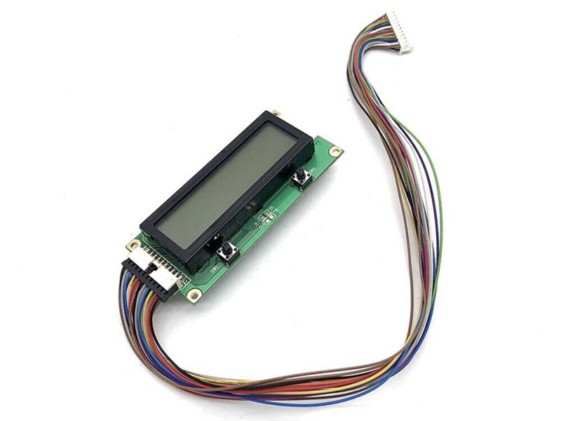
Modern electronic systems rely heavily on displays—LCDs in industrial HMIs, TFT panels in vehicles, control screens in medical devices, and compact touch displays in embedded systems. While displays are often treated as standalone components, engineers know that the reliability of the cable connecting the display to the control electronics can determine the success or failure of the entire system. This is where the term “DCP cable” frequently appears in specifications, emails, drawings, and engineering discussions.
Interestingly, DCP cable is not a formal IEC or ISO cable category. Instead, it is an application-driven term used in engineering and manufacturing environments to describe a cable assembly that connects a Display Control Panel to a main control board or processing unit. Because it is not standardized, confusion is common—especially for buyers who only have a photo, a partial model number, or a legacy sample.
A DCP cable, commonly meaning Display Control Panel cable, is a custom cable assembly used to connect a display module to a control board. It typically carries high-speed display signals such as LVDS or eDP, along with control and power lines. DCP cables are not standardized products; they are application-specific assemblies defined by connector type, pinout, signal requirements, shielding, and environmental conditions.
Behind this simple definition lies a complex reality: different signal standards, connector constraints, EMI risks, mechanical routing challenges, and supply-chain decisions all shape what a DCP cable actually looks like. In the sections below, we’ll break this down step by step—so you can recognize, specify, and source the right DCP cable, not just a cable that “looks similar.”
What Is a DCP Cable?

A DCP cable, commonly understood as a Display Control Panel cable, is an application-level cable assembly used to connect a display module to its host control electronics. In most systems, it forms the critical link between an LCD or TFT panel and a main control board, processor, or embedded controller. Through this single assembly, the system transmits high-speed display data, control signals, grounding references, and in some cases low-current power required for display operation.
DCP Cable as a Functional Term, Not a Standardized Cable Type
It is important to clarify that “DCP cable” is not a formal, standardized cable category defined by IEC, ISO, or IPC specifications. Instead, it is a functional term widely used in engineering, manufacturing, and OEM communication.
Engineers use the term to describe the role a cable plays within a system rather than its internal structure or material composition. As a result, two DCP cables used in different products may look completely different—using different connectors, cable structures, or shielding methods—while still serving the same functional purpose of linking a display panel to its control electronics.
This functional naming convention is common in system-level design, where cables are identified by what they connect, not by how they are built.
Why DCP Cables Are Almost Always Custom-Designed
In practical terms, a DCP cable is rarely an off-the-shelf product. Its final design depends on multiple system-specific factors, including:
- Display interface standard (such as LVDS or eDP)
- Signal speed and signal integrity requirements
- Connector type, pitch, and orientation
- Pinout definition and signal mapping
- Cable length and mechanical routing constraints
- Environmental conditions such as temperature, vibration, and EMI exposure
Because display signals operate at relatively high frequencies, even small variations in cable construction—such as impedance inconsistency, shielding effectiveness, or conductor spacing—can directly affect image stability, EMI performance, and long-term reliability. For this reason, DCP cables are typically engineered as project-specific assemblies, optimized for both electrical and mechanical performance.
Why the Term “DCP Cable” Is Widely Used in Engineering Communication
Another reason the term “DCP cable” is commonly used is communication efficiency. During early-stage design discussions, engineers often refer to “the DCP cable” as a shorthand way to describe the entire display interconnection without listing every electrical and mechanical detail.
While this approach works well within engineering teams, it can create confusion when the request moves to procurement or external suppliers—especially if the only information provided is a photo, a partial connector model, or a legacy sample. Without clarification, different parties may assume different signal standards or construction methods.
This is why experienced manufacturers treat “DCP cable” not as a finished product description, but as the starting point of a technical clarification process.
How Manufacturers Interpret a DCP Cable Requirement
For cable assembly manufacturers, a DCP cable represents a project definition rather than a catalog item. The focus is on translating system intent into a manufacturable solution by confirming electrical, mechanical, and compliance requirements.
The table below summarizes how a DCP cable is typically understood in practice:
| Aspect | What It Means in a DCP Cable Project |
|---|---|
| Naming | Functional, application-driven term |
| Standardization | No fixed IEC / ISO definition |
| Design approach | Custom, system-specific |
| Key focus | Signal integrity + mechanical reliability |
| Typical output | Approved drawing + validated cable assembly |
This clarification-driven approach ensures that the final DCP cable performs reliably in real-world operation, rather than simply matching a visual reference or part number.
What a DCP Cable Really Represents
In essence, a DCP cable is not a single, fixed cable type, but a flexible engineering concept. It describes a critical interconnection between a display and its control electronics—one that must be carefully designed, validated, and manufactured based on the specific requirements of the system it serves.
What Is a DCP Cable Used For?

DCP cables are used to connect display modules—such as LCD or TFT panels—to control boards in industrial, automotive, medical, and embedded systems. They transmit display data, timing signals, control commands, and sometimes power, ensuring stable image output and responsive user interaction.
DCP cables appear wherever displays are integrated into functional equipment rather than consumer plug-and-play devices. Common scenarios include:
- Industrial HMIs: Control panels on machinery require stable, noise-resistant display connections over long operating lifetimes.
- Automotive Displays: Instrument clusters and infotainment systems demand compact, vibration-resistant cables with consistent impedance.
- Medical Equipment: Diagnostic displays often require biocompatible materials and strict EMI control.
- Embedded Systems: Single-board computers paired with LCD panels rely on compact DCP assemblies for space efficiency.
What unites these applications is not the display itself, but the system-level expectation: reliability under real-world conditions. Unlike consumer HDMI cables, DCP cables are rarely standardized or stocked. They are engineered around enclosure constraints, connector ecosystems, and compliance rules.
This is also why off-the-shelf replacements often fail. A cable that “fits” mechanically may introduce signal reflections, EMI leakage, or premature fatigue—issues that only appear after deployment.
Which Signals Does a DCP Cable Carry?
A DCP cable typically carries a combination of high-speed display signals, low-speed control signals, grounding references, and in some cases low-current power lines. The exact signal composition is not fixed; instead, it is determined by the display interface standard, resolution, refresh rate, system architecture, and electrical noise environment of the device.
Unlike consumer video cables, which usually handle a single standardized signal type, DCP cables must support multiple signal domains within one assembly. This multi-signal nature is one of the main reasons DCP cables require careful engineering rather than simple visual matching.
High-Speed Display Data Signals
The core function of a DCP cable is to transmit display image data from the host controller to the display panel. These signals operate at relatively high frequencies and are highly sensitive to impedance variation, crosstalk, and EMI.

Common high-speed display signal standards include:
- LVDS (Low-Voltage Differential Signaling) – widely used in industrial, automotive, and embedded displays due to its robustness and EMI resistance
- eDP (Embedded DisplayPort) – used in higher-resolution or higher-bandwidth display systems
- In some legacy or low-resolution systems, parallel RGB or similar interfaces may still appear
These signals are almost always implemented as differential pairs, requiring tight control of impedance, pair matching, and routing symmetry throughout the cable assembly.
Low-Speed Control and Communication Signals
In addition to image data, DCP cables often carry several low-speed control signals that manage display behavior and system coordination.
Typical control signals include:
- I²C or similar communication buses for panel configuration and status feedback
- Reset and enable signals for panel initialization
- Touch or auxiliary control lines (when integrated into the same cable)
Although these signals operate at much lower frequencies than display data, they must still be properly routed and referenced to ground to avoid coupling noise into adjacent high-speed pairs.
Power and Backlight-Related Signals
Many DCP cables also include low-current power lines, particularly for control logic or backlight control circuits. In some designs, higher-current backlight power is routed separately, but in compact systems it may be partially integrated into the DCP cable.
Common power-related signals include:
- Logic-level supply voltages for display control circuits
- Backlight enable signals
- PWM dimming lines for brightness control
Power conductors must be sized and routed carefully to prevent voltage drop, thermal buildup, or interference with sensitive signal lines.
Grounding and Shielding References
Ground and shielding are not “secondary” signals in a DCP cable—they are fundamental to signal integrity. Proper grounding ensures stable reference levels for both high-speed and low-speed signals, while shielding reduces susceptibility to external noise and prevents emissions from affecting nearby components.
Grounding strategies may include:
- Dedicated ground wires
- Drain wires tied to shields
- Overall or individual pair shielding, depending on signal speed
The grounding scheme is always system-dependent and must align with the grounding strategy of both the display and the control board.
Typical Signal Composition in a DCP Cable
The table below summarizes the most common signal categories found in DCP cable assemblies:
| Signal Category | Purpose | Typical Characteristics |
|---|---|---|
| High-speed display data | Transmit image data | Differential pairs, impedance-controlled |
| Low-speed control | Panel configuration & control | Single-ended or low-speed differential |
| Power / backlight | Support display operation | Low to moderate current |
| Ground / shield reference | Signal stability & EMI control | Continuous reference paths |
This mix of signal types is what makes DCP cables more complex than they appear at first glance.
Why Signal Definition Matters in DCP Cable Design
One of the most common issues in DCP cable projects arises when signal definitions are incomplete or assumed. Two cables with identical connectors may carry entirely different signal assignments, leading to functional failure or long-term reliability issues if substituted incorrectly.
For this reason, professional cable manufacturers treat signal definition and pin mapping as a critical design step, often requiring drawings and confirmation before production. Clear signal identification ensures that the final DCP cable not only fits mechanically, but also performs reliably under real operating conditions.
Key Takeaway for Engineers and Buyers
A DCP cable does not carry “just one type of signal.” It is a multi-signal assembly that integrates display data, control, power, and grounding into a single engineered solution. Understanding this signal composition is essential when specifying, sourcing, or replacing a DCP cable—especially in applications where reliability, EMI performance, and long-term stability are critical.
How Is a DCP Cable Constructed?
DCP cables are built using structures such as micro-coaxial conductors, shielded twisted pairs, or hybrid combinations. Construction choices are driven by signal speed, EMI requirements, flexibility, and mechanical routing constraints.

At the conductor level, many DCP cables rely on micro-coaxial lines for high-speed channels. These provide excellent impedance control and EMI containment in compact form factors. Shielded twisted pairs are also used where flexibility and cost balance allow.
Below is a simplified comparison of common internal structures:
| Cable Structure | Typical Use Case | Key Advantages | Limitations |
|---|---|---|---|
| Micro-Coax | High-speed LVDS/eDP | Best EMI control, stable impedance | Higher cost |
| Shielded Twisted Pair | Medium-speed signals | Flexibility, cost efficiency | Larger OD |
| Hybrid (Coax + Power) | Integrated assemblies | Compact routing | Complex manufacturing |
Beyond conductors, jacket materials influence durability and compliance. Options range from PVC and TPE to high-temperature, halogen-free compounds for demanding environments.
How Do You Choose the Right DCP Cable?
Choosing the right DCP cable requires confirming connector models, pinout definitions, signal standards, length, routing, and environmental conditions. When specifications are incomplete, drawings, samples, or engineering discussions are essential to avoid mismatches.
In real projects, buyers often provide:
- A connector part number without pin mapping
- A photo without electrical data
- A legacy sample with no documentation
This is normal—but risky. Experienced manufacturers mitigate this by reverse-engineering samples, validating pinouts, and producing CAD drawings for customer approval before production.
Below is a practical checklist engineers should confirm:
| Specification Area | Why It Matters |
|---|---|
| Connector Type & Pitch | Mechanical compatibility |
| Pinout Definition | Prevents signal mis-routing |
| Cable Length & OD | Affects impedance and routing |
| EMI & Shielding | System compliance |
| Environment | Heat, oil, UV resistance |
This process transforms vague requests into production-ready designs.
Can DCP Cables Be Customized?
Yes. DCP cables are almost always customized. Length, pin mapping, connector options, cable structure, and materials can all be adjusted to match system requirements without changing the display or control electronics.
Customization as a Design Advantage
Customization is not a luxury—it’s the default for DCP cables. Even small changes in enclosure layout can require different lengths or exit orientations. Connector sourcing decisions (original vs compatible) influence lead time, cost, and supply stability.
Customization also enables optimization:
- Reducing OD for tight routing
- Improving flexibility at hinge points
- Enhancing EMI shielding for certification
This flexibility is why manufacturers with no MOQ and fast drawing turnaround are preferred partners in display projects.
How Are DCP Cables Designed and Manufactured?
DCP cables are designed through a structured process: requirement intake, pinout definition, CAD drawing, customer approval, prototyping, testing, and controlled production with 100% inspection.
Errors in display cables are costly—they often appear only after system integration. A disciplined workflow reduces risk. Drawings act as a contract between customer and manufacturer, ensuring both sides agree before tooling and assembly begin.
Quality control typically includes:
- In-process inspection
- Electrical continuity and impedance checks
- Final inspection before shipment
This level of control is essential for mission-critical displays.

Ready to Customize Your DCP Cable with Sino-Conn?
Whether you’re an engineer finalizing a next-generation display system, an OEM optimizing cost without sacrificing reliability, or a procurement team sourcing from drawings, samples, or reference photos, Sino-Conn is built to deliver—not just quote.
We support the entire DCP cable lifecycle:
from requirement clarification and connector selection, to rapid prototyping, validation, and stable mass production. No vague assumptions, no black-box manufacturing—every project starts with engineering review and confirmed drawings before production.
Share your connector models, pin definitions, drawings, samples, or even just photos. Our engineering team will quickly convert your input into a manufacturable, compliant, and cost-optimized DCP cable assembly—often within hours for urgent projects.
With no MOQ, fast samples, flexible connector options, and full compliance support, Sino-Conn helps you move faster, reduce risk, and bring your product to market with confidence.
Start your DCP cable inquiry with Sino-Conn today—and turn your design into a production-ready solution.


