 Skip to content
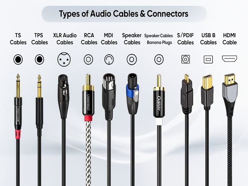
Modern life runs on connections — not just digital ones, but physical links made of metal, insulation, and precision. Every smartphone, robot arm, aircraft, or factory line depends on the correct combination of cables and connectors to transmit power, data, or signals reliably. Yet, behind this everyday simplicity lies a complex world of engineering choices: conductor materials, shielding designs, voltage ratings, temperature limits, and connector interfaces that must all work in harmony.
Cables transmit electrical or optical energy, while connectors mechanically and electrically join cables or devices. Together, they form assemblies that carry power, data, or signals. The right pairing ensures efficiency, durability, and safety across industries — from telecommunications to aerospace. Understanding cable and connector types helps engineers select optimal designs for performance, flexibility, and environmental resistance.
Selecting the right cable and connector is not just about matching part numbers — it’s about matching intent. A cable may look similar in diameter or color, yet its insulation, shielding, and flexibility can dramatically affect long-term performance. Likewise, the connector’s plating or locking mechanism may determine whether a system lasts months or decades. Let’s explore how cables and connectors differ, how they’re categorized, and how to make informed design choices.
What Is the Difference Between a Cable and a Connector?
A cable is a transmission medium composed of conductors, insulation, and shielding used to carry electrical power or data signals. A connector is an electromechanical component that joins conductors or devices to establish a detachable connection. While a cable provides the path for current or information to flow, a connector enables safe, reliable, and repeatable interfacing between components. Together, they form a complete cable assembly used in power systems, automation, telecommunications, and electronic devices.
Definitions and Core Functions
Although the terms cable and connector are often used together, they represent different yet complementary functions in an electrical system.
- Cable: A cable consists of one or more conductors surrounded by insulation and protective layers. It acts as the pathway that allows current, voltage, or optical signals to flow between two points. Its design focuses on transmission efficiency, flexibility, and environmental resistance.
- Connector: A connector, on the other hand, is a device that links cables to equipment, other cables, or circuit boards. It provides the interface — ensuring electrical continuity, mechanical retention, and ease of assembly or maintenance.
In simpler terms:
Cables carry signals; connectors connect them.
However, in practical engineering, these two elements must function as one integrated unit — a cable assembly — to ensure reliable system operation.
Physical and Functional Differences
Cables and connectors differ not just in appearance, but in structure, performance criteria, and engineering purpose. The table below summarizes these differences:
| Aspect | Cable | Connector |
|---|---|---|
| Function | Transmit electrical or optical signals | Join or terminate cables and devices |
| Core Components | Conductor, insulation, shielding, outer jacket | Contacts, housing, locking mechanism, shell |
| Primary Role | Energy or data transmission | Electrical/mechanical interfacing |
| Performance Focus | Conductivity, flexibility, EMI protection | Contact resistance, mating cycles, sealing |
| Reusability | Typically permanent in installation | Detachable and reusable |
| Examples | Power cable, Cat6 data cable, coaxial cable | RJ45, SMA, USB, M12 connectors |
While the cable determines how well the signal travels, the connector determines how reliably that signal reaches its destination without interruption, distortion, or mechanical failure.
Structural Guide: From Core to Interface
1. Cable Structure
A standard cable includes several engineered layers:
- Conductor: The core wire (copper, aluminum, or tinned copper) that carries current or data.
- Insulation: Non-conductive material (PVC, PE, PTFE) that isolates the conductor and prevents short circuits.
- Shielding: Metallic braid or foil that reduces electromagnetic interference (EMI).
- Outer Jacket: The external sheath that resists mechanical wear, oil, UV exposure, and temperature extremes.
Each layer contributes to specific performance metrics — flexibility, dielectric strength, or attenuation loss.
2. Connector Structure
A connector includes multiple subcomponents:
- Contacts: The conductive pins or sockets that touch and transmit the signal.
- Insulator (Dielectric): Separates contacts within the connector housing.
- Housing/Shell: Provides physical protection and alignment; can be plastic or metal.
- Locking Mechanism: Threaded coupling, bayonet, latch, or push-pull design ensuring mechanical stability.
- Backshell or Strain Relief: Prevents stress or bending damage where the cable meets the connector.
While cables are linear transmission paths, connectors are precision-machined interfaces designed for repeatable mating without signal loss or degradation.
Electrical Behavior: Continuity vs Contact Integrity
From an electrical perspective, both cables and connectors must preserve signal integrity but in different ways:
- Cables maintain continuity by minimizing resistance and impedance variation across their length. A poorly designed cable may cause voltage drop, signal reflection, or EMI leakage.
- Connectors maintain contact integrity — ensuring minimal contact resistance and consistent impedance through proper mating pressure, plating, and geometry.
Even if the cable itself is perfect, a poorly chosen or corroded connector can cause major system failures due to contact oxidation, vibration, or improper crimping.
For example:
- A Cat6 cable might support 1 Gbps Ethernet, but if paired with a low-quality RJ45 connector, crosstalk or signal loss may limit real speed to under 500 Mbps.
- Similarly, a high-power DC cable with an undersized crimp terminal may heat up and fail under load, despite the cable’s correct gauge.
Mechanical Interaction: Strength and Strain Relief
Beyond electrical performance, mechanical design determines long-term reliability.
- Cables must remain flexible and withstand bending, pulling, and abrasion. Stranded conductors improve flexibility, while reinforced jackets increase strength.
- Connectors must withstand repeated mating cycles (typically 500–5,000 insertions). Materials like gold-plated brass or stainless steel are used to maintain consistent contact pressure and corrosion resistance.
- Strain Relief: The point where the cable meets the connector is the most common failure location. Quality assemblies use molded boots, clamp-style backshells, or overmolding to distribute stress evenly.
How They Work Together in Real Assemblies
In actual assemblies, cables and connectors are complementary — neither can perform alone.
Their interaction defines both signal reliability and service life.
Power Transmission Example:
- Cable: Multi-stranded copper wire with PVC insulation (e.g., 3×1.5 mm²).
- Connector: IEC 320 C13/C14 or Molex Mini-Fit Jr.
- Application: Powering computers or appliances up to 10 A.
Data Communication Example:
- Cable: Cat6 twisted pair with 100 Ω impedance.
- Connector: 8P8C RJ45 plug or jack.
- Application: Ethernet networking up to 10 Gbps.
RF Transmission Example:
- Cable: RG-58 coaxial cable (50 Ω).
- Connector: SMA or BNC connector.
- Application: RF signal lines in test equipment and antennas.
Industrial Automation Example:
- Cable: PUR-jacketed multi-core control cable.
- Connector: M12 circular connector with IP67 sealing.
- Application: Robotics, sensors, and PLC wiring under vibration.
In every case, impedance, current rating, and mechanical fit must align precisely between cable and connector — even a small mismatch (for example, a 50 Ω cable with a 75 Ω connector) can degrade performance or damage equipment.
Design Considerations: Engineering Compatibility
When specifying a cable-connector pair, engineers consider the following compatibility factors:
| Parameter | Cable Concern | Connector Concern | Goal |
|---|---|---|---|
| Impedance | Defined by dielectric geometry | Must match cable impedance | Signal integrity |
| Voltage Rating | Depends on insulation | Determined by creepage/clearance | Safety margin |
| Current Capacity | Conductor size | Contact cross-section | Heat management |
| Environmental Resistance | Jacket & shield material | Housing & sealing (IP67/68) | Durability |
| Mechanical Fit | OD tolerance | Crimp/strain relief size | Secure termination |
Failure to align these factors can result in overheating, EMI leakage, or connector failure — particularly in high-frequency or high-vibration environments.
Examples of Mismatched Design Consequences
To illustrate the importance of matching, consider these real-world cases:
- Overheating: Using a 20 AWG cable on a 10 A circuit with a small connector pin rated for only 5 A can cause excessive heat buildup.
- Signal Loss: Pairing a 50 Ω coax with a 75 Ω connector creates reflection points, lowering RF transmission efficiency.
- Ingress Failure: An outdoor assembly using a non-sealed connector can allow water ingress, corroding both cable conductors and contacts.
- Mechanical Fatigue: A rigid cable mated with a lightweight connector can stress the solder joints, leading to intermittent failure.
What Are the Main Types of Electrical Cables?
Electrical cables are classified by purpose—power, data, control, or specialty—and differ in conductor size, insulation material, shielding, and voltage rating. Major types include power cables for energy transmission, communication cables for data signals, coaxial cables for RF, control and instrumentation cables for automation, and custom or high-performance cables for specialized industries. Each type balances electrical performance with mechanical flexibility, safety, and environmental resistance to meet its intended application.
1. Power Cables
Power cables are designed primarily for carrying electrical energy rather than information. Their construction varies depending on voltage level and installation environment.
Key Characteristics
- Voltage Range: 300 V to 35 kV or higher
- Conductors: Copper or aluminum (solid or stranded)
- Insulation Materials: PVC, XLPE (cross-linked polyethylene), or EPR (ethylene-propene rubber)
- Sheath Options: PVC for indoor use; PE or armored steel tape for outdoor or underground installations
Common Sub-Types
| Cable Type | Rated Voltage | Typical Use | Notes |
|---|---|---|---|
| Building Wire (THHN/THW) | 300–600 V | Residential, commercial wiring | Flame-retardant PVC jacket |
| Flexible Power Cord (H05VV-F) | 250 V | Portable equipment, lighting | Excellent flexibility |
| Medium-Voltage Cable (XLPE-insulated) | 6–35 kV | Industrial plants, substations | Heat- and moisture-resistant |
| Armored Power Cable (SW/AW) | 1–15 kV | Underground or mechanical stress areas | Steel/aluminum wire armor |
Design Considerations
- Conductor Size (AWG/mm²): Determines current capacity and voltage drop.
- Thermal Rating: XLPE can handle up to 90 °C continuous operation.
- Environment: Outdoor cables require UV, oil, and moisture resistance.
Power cables are often the heaviest and least flexible, but they are engineered for long-term stability, safety, and high current loads.
2. Data and Communication Cables
Data cables are optimized for signal transmission speed, integrity, and low interference, rather than power handling.
Main Families
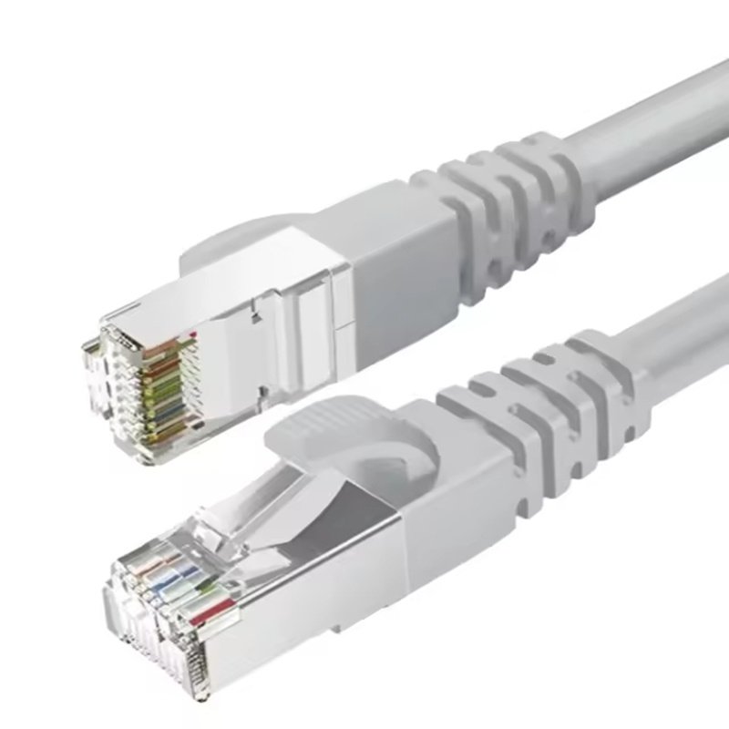
- Twisted-Pair Cables (Copper)
- Found in Ethernet networks (Cat5e, Cat6, Cat6A, Cat7).
- Characterized by balanced 100 Ω impedance and twisted conductor pairs that cancel crosstalk.
- Shielding styles:
- UTP (Unshielded Twisted Pair) – economical, flexible
- STP/FTP (Shielded/Foil Twisted Pair) – enhanced EMI protection
- Fiber-Optic Cables
- Transmit light instead of electricity, immune to electromagnetic interference.
- Two main types:
- Single-Mode (SMF): Long-distance, narrow core (~9 µm).
- Multi-Mode (MMF): Shorter-distance, wider core (50–62.5 µm).
- Used in data centers, telecommunications, and medical imaging.
- USB, HDMI, and Display Cables
- High-speed data interfaces for consumer electronics and computers.
- Utilize shielded differential pairs and braided copper shields to maintain signal fidelity up to 10 Gbps (USB 3.1).
Key Design Metrics
| Parameter | Typical Value | Purpose |
|---|---|---|
| Characteristic Impedance | 100 Ω (twisted-pair), 75 Ω (video) | Prevents signal reflection |
| Bandwidth | Up to 600 MHz (Cat7) | Determines data rate |
| Shielding Coverage | 80–100 % | EMI protection |
| Max Length | 100 m (Cat6), >10 km (fiber) | Signal attenuation control |
3. Coaxial Cables
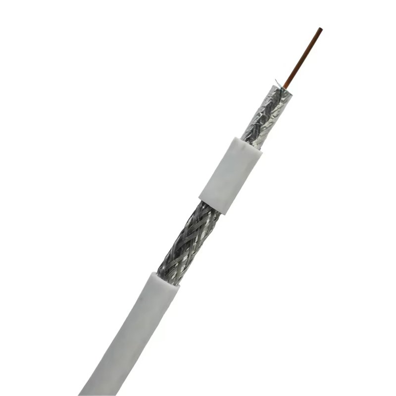
Coaxial cables (or “coax”) are specifically engineered for radio frequency (RF) and broadband transmission applications. Their concentric structure provides excellent shielding and impedance stability across high frequencies.
Basic Construction
- Inner Conductor: Solid or stranded copper.
- Dielectric Insulation: PE, PTFE, or foam PE controlling impedance.
- Outer Shield: Braided copper or aluminum foil for EMI protection.
- Jacket: PVC, PE, or FEP depending on environment.
Common Types and Impedance
| Coax Type | Impedance | Outer Diameter | Typical Application |
|---|---|---|---|
| RG-174 | 50 Ω | 2.8 mm | Compact RF modules |
| RG-58 | 50 Ω | 5 mm | Test cables, WLAN |
| RG-6 | 75 Ω | 6.9 mm | Cable TV, satellite |
| RG-11 | 75 Ω | 10 mm | Long-distance broadband |
| LMR-400 | 50 Ω | 10 mm | Cellular, 5G repeaters |
Performance Factors
- Attenuation: Loss increases with frequency and length.
- Flexibility: Smaller diameters allow tighter bends but higher loss.
- VSWR (Voltage Standing Wave Ratio): Indicates impedance match between cable and connector (ideal < 1.3:1).
Sino-Conn supplies both 50 Ω and 75 Ω coaxial assemblies for applications ranging from RF test benches to satellite systems, with matching SMA, N-type, or BNC connectors.
4. Control and Instrumentation Cables

Control cables bridge electrical signals between machines and sensors, providing both power and communication functions in automation systems.
Characteristics
- Core Count: Typically 2–60 cores, depending on complexity.
- Voltage Rating: 300–600 V.
- Shielding: Foil and braid combinations reduce industrial EMI.
- Jacket: PVC for fixed installations; PUR for robotic or mobile use.
Typical Standards
- UL 2464 / UL 2517: Multi-conductor signal and control cable.
- VDE 0812 / IEC 60332: Flame-retardant and oil-resistant standards.
- CSA C22.2 No. 210: North American industrial compliance.
Example Applications
| Environment | Cable Design | Purpose |
|---|---|---|
| Factory Automation | Shielded multi-core PUR cable | Connects sensors/actuators to PLCs |
| Robotics | Extra-flexible drag-chain cable | Withstands ≥5 million bending cycles |
| Energy Plants | Halogen-free control cable | Ensures low smoke/toxicity in fire events |
Control cables are chosen not only for electrical ratings but also for mechanical endurance—resisting torsion, chemicals, and repeated motion without signal degradation.
5. Specialty and Custom Cables

Beyond standardized designs, many industries demand cables with tailored electrical, mechanical, and environmental performance. Sino-Conn specializes in these custom constructions.
High-Temperature Cables
- Materials: PTFE, FEP, or silicone insulation.
- Operating Range: −70 °C to +250 °C.
- Applications: Aerospace avionics, industrial furnaces, defense electronics.
Medical-Grade Cables
- Requirements: Biocompatibility, sterilization tolerance, miniature diameter (< 1.5 mm).
- Materials: FEP or TPU with silver-plated copper conductors.
- Applications: Ultrasound probes, endoscopes, diagnostic imaging.
Automotive & EV Cables
- Features: Lightweight, halogen-free, high vibration resistance.
- Examples:
- LVDS and FAKRA coax for cameras and sensors.
- High-voltage orange cables rated up to 600 V DC for EV powertrains.
Marine and Subsea Cables
- Construction: Water-blocking tapes, tinned copper, and UV-resistant PE jackets.
- Special Property: Pressure tolerance up to several hundred meters underwater.
Hybrid Cables
- Combine power, signal, and fiber in one jacket for compact assemblies.
- Common in surveillance, robotics, and renewable-energy systems.
Such customization allows engineers to minimize space and improve reliability by integrating multiple functions into a single, ruggedized cable system.
6. Cable Selection Parameters
When choosing between cable types, engineers analyze several measurable attributes:
| Parameter | Influence on Design | Typical Range / Standard |
|---|---|---|
| Voltage Rating | Determines insulation thickness | 300 V – 35 kV |
| Temperature Range | Material-dependent | −70 °C to +250 °C |
| Flexibility (Bend Radius) | Affects routing in equipment | ≥ 5 × OD |
| EMI Protection | Via shield type | Foil / Braid / Hybrid |
| Flame Resistance | Safety standard compliance | UL VW-1, IEC 60332 |
| Chemical & Oil Resistance | Material selection | PUR > PVC > PE |
| Environmental Rating | Outdoor/IP protection | IP54–IP68 (with connector) |
What Types of Connectors Are Commonly Used?
Connectors are electromechanical components that join cables or devices, providing detachable electrical or signal connections. Common connector categories include power connectors, data and signal connectors, RF/coaxial connectors, board-to-wire systems, and industrial or circular connectors. Each type differs in voltage rating, contact configuration, mechanical durability, and environmental sealing. Selecting the correct connector ensures reliable transmission, proper impedance, and long-term performance across industries—from automation and telecom to aerospace and medical electronics.
1. Power Connectors

Power connectors handle the transfer of electrical energy between equipment, power sources, and loads.
They are designed to carry higher currents safely and minimize resistive losses.
Key Characteristics
- Voltage rating: 125 V – 600 V (AC or DC)
- Current rating: 1 A – 500 A
- Contact materials: Brass, copper alloy, or phosphor bronze with tin/nickel/gold plating
- Safety features: Polarized housings, keyed interfaces, locking mechanisms, and insulation barriers
Main Types
| Connector Type | Typical Rating | Application | Notes |
|---|---|---|---|
| IEC C13/C14 | 10 A / 250 V | Desktop electronics, servers | Global standard for AC mains |
| Molex Mini-Fit Jr. | 13 A / 600 V | Power supplies, automotive | Compact high-density connector |
| Anderson Powerpole | 15–350 A / 600 V | Battery, solar, UPS systems | Genderless modular housing |
| Circular DIN (3-24 pins) | 5–20 A | Industrial sensors, robotics | Locking thread prevents vibration |
| DC barrel jack / plug | < 5 A / 24 V | Consumer devices | Simple, inexpensive |
Design Considerations
- Contact resistance: < 10 mΩ for efficient conduction.
- Temperature rise: ≤ 30 °C under rated load.
- Mating cycles: 500 – 5,000 depending on material.
- Creepage/clearance: Critical for high-voltage safety compliance (UL 1977, IEC 61984).
Power connectors are found in virtually every system—from household appliances to industrial drives—and are essential for safe, stable energy delivery.
2. Data and Signal Connectors

Data connectors are designed for transmitting low-power electrical signals—digital or analog—with minimal noise, crosstalk, and attenuation.
Common Families
| Interface | Bandwidth / Speed | Primary Use |
|---|---|---|
| RJ45 (Ethernet) | Up to 10 Gbps | Networking, industrial IoT |
| USB Type-A / C | 480 Mbps – 40 Gbps | Computers, chargers, peripherals |
| HDMI / DisplayPort | 10–48 Gbps | Video, audio, multimedia |
| D-Sub (9–37 pins) | < 1 Gbps | Legacy serial ports (RS-232/485) |
| M8 / M12 Industrial Ethernet | 100 Mbps – 1 Gbps | Automation, sensors |
| Micro-/ Mini-USB | Up to 480 Mbps | Portable devices |
Electrical Features
- Characteristic impedance: Typically 100 Ω for differential pairs.
- Shielding: Metal shells or braid termination reduce EMI.
- Contact plating: Gold over nickel ensures signal stability over many cycles.
- Insertion loss (IL): < 1 dB up to rated frequency to preserve data integrity.
Mechanical & Environmental Features
- Snap-fit or screw-lock coupling for vibration resistance.
- Compact, high-density layouts (e.g., USB-C = 24 contacts in 8.4 mm width).
- Sealed versions (M12 X-coded) provide IP67/IP68 protection for outdoor networking.
High-speed digital systems depend heavily on these precision connectors to maintain signal fidelity; even micro-level misalignment can cause reflection or bit errors.
3. RF and Coaxial Connectors

RF (radio-frequency) connectors are specialized for frequencies from 1 MHz to 50 GHz, requiring strict impedance control and low reflection.
Common Types
| Connector | Impedance | Frequency Range | Applications |
|---|---|---|---|
| SMA | 50 Ω | DC – 26.5 GHz | Wi-Fi, 5G, instrumentation |
| SMB / SMC | 50 Ω | DC – 10 GHz | Compact RF modules |
| BNC | 50 Ω / 75 Ω | DC – 4 GHz | Video, lab test setups |
| N-type | 50 Ω / 75 Ω | DC – 11 GHz | Base stations, antennas |
| FAKRA / Z-series | 50 Ω | DC – 6 GHz | Automotive (ADAS, cameras) |
| TNC | 50 Ω | DC – 11 GHz | Ruggedized BNC variant |
Engineering Criteria
- VSWR (Voltage Standing Wave Ratio): ≤ 1.2 typical for matched systems.
- Contact durability: 500 – 2,000 mating cycles.
- Dielectric material: PTFE for low loss; PE for cost-efficient designs.
- Coupling mechanism: Threaded (SMA), bayonet (BNC), or snap-on (SMB).
Performance Example
A 50 Ω SMA connector with silver-plated contacts can handle > 500 W CW at 1 GHz with insertion loss < 0.1 dB—critical for radar, 5G, and satellite systems.
Precision machining and plating ensure reliable operation even in vibration-prone environments.
4. Board-to-Wire and Wire-to-Wire Connectors

These connectors provide modular interconnection within equipment, linking PCBs, harnesses, or internal subsystems.
Categories
- Board-to-Wire: Female housing with crimped terminals mates to male PCB header.
- Wire-to-Wire: Two cable harnesses joined via latch or friction lock housings.
- IDC (Insulation Displacement Connectors): Mass-termination for ribbon cables without stripping insulation.
Examples
| Series / Brand Example | Pitch | Current Rating | Typical Use |
|---|---|---|---|
| JST PH / XH | 2.0 / 2.5 mm | 2–3 A | Consumer electronics |
| Molex Micro-Fit | 3.0 mm | 5 A | Industrial control |
| TE AMP-MODU | 2.54 mm | 1 A | PCB signal routing |
| IDC Ribbon (2×5 to 2×25)** | 2.54 mm | 0.5 A | Embedded systems |
| Circular Mini Series | 1–2 mm | < 1 A | Compact sensors |
Advantages
- Quick assembly, standardized pitch, low-profile height.
- Polarized design prevents reverse mating.
- Cost-effective for mass production.
Design Note
Crimp-terminal quality is vital—poor crimp force or over-crimping can raise resistance or fracture strands. Sino-Conn employs calibrated presses and 100 % pull-test inspection to ensure uniform terminations.
5. Circular and Industrial Connectors

Circular connectors are ruggedized interfaces used in factory automation, heavy machinery, and transportation, valued for mechanical strength and ingress protection.
Main Standards
| Series | Contact Count | IP Rating | Key Feature |
|---|---|---|---|
| M5 / M8 / M12 | 3 – 12 | IP67 / IP68 | Compact field sensors |
| 7/8-inch Industrial | 2 – 5 | IP67 | Power distribution |
| MIL-C-5015 / MIL-DTL-38999 | 3 – 128 | IP68 / hermetic | Aerospace & defense |
| Binder / Harting Circular | 2 – 24 | IP67 | Factory automation |
| Push-Pull (Lemo / ODU style) | 2 – 19 | IP68 / medical | Quick connect/disconnect |
Material Options
- Shells: Brass, stainless steel, or anodized aluminum.
- Insulators: PBT, PPS, or PTFE.
- Seals: Silicone or EPDM gaskets for waterproofing.
Mechanical Performance
- Mating cycles: 1,000 – 10,000+.
- Vibration resistance: Up to 10 g RMS.
- Operating temperature: −40 °C to +125 °C (PUR/PBT) or +250 °C (PTFE).
Circular connectors balance compactness with robustness and are widely used in robotic arms, electric vehicles, medical imaging systems, and outdoor communication stations.
6. Specialized and Custom Connectors

Certain applications require non-standard or hybrid designs combining multiple signal types in a single interface—an area where Sino-Conn provides significant customization expertise.
Hybrid Power + Data Connectors
- Carry both low-voltage control and high-current supply lines.
- Reduce cabling complexity in AGVs, EV chargers, and automation tools.
Medical-Grade Connectors
- Comply with ISO 13485 and IEC 60601.
- Use biocompatible, sterilizable materials (PEEK, PSU, TPU).
- Typical in ECG leads, surgical handpieces, diagnostic probes.
High-Temperature / Aerospace Connectors
- Silver- or nickel-plated contacts for > 200 °C operation.
- Fluoropolymer or glass-sealed housings resist outgassing.
- Essential for avionics, satellites, and defense electronics.
Waterproof / Outdoor Connectors
- Rated up to IP69K; withstand direct water jets or submersion.
- Common in marine, renewable-energy, and surveillance equipment.
7. Key Parameters When Choosing a Connector
| Category | Primary Metric | Typical Range | Selection Goal |
|---|---|---|---|
| Electrical | Current & Voltage Rating | 0.1 A – 500 A / 5 V – 1 kV | Match system power demand |
| Mechanical | Mating Cycles | 100 – 10,000 + | Longevity under service |
| Environmental | IP Rating / Temp Range | IP20 – IP69K / −55 – +250 °C | Fit operating conditions |
| Material | Plating & Housing | Gold, Tin, Nickel / Plastic or Metal | Corrosion resistance |
| Size | Contact Pitch / Shell OD | 1 mm – 25 mm | Compatibility & density |
| Regulation | UL / RoHS / REACH | Certified / Compliant | Safety and global acceptance |
Selecting the correct connector involves balancing these parameters to ensure that electrical, mechanical, and environmental requirements are all met.
8. Connector Trends and Innovations
Modern trends reflect growing demand for miniaturization, higher data rates, and harsh-environment resilience:
- Mini connectors: Micro-coax and nano-circular types for drones, wearables, and IoT.
- High-speed I/O: USB-4 (40 Gbps), QSFP-DD (400 Gbps).
- Hybrid modularity: Combine power, Ethernet, and pneumatics in one shell (used in robotics).
- Smart connectors: Embedded chips for identification, power monitoring, or predictive maintenance.
- Eco-friendly materials: Halogen-free plastics and recyclable metals to meet RoHS 3 and REACH SVHC requirements.
How Do Cable and Connector Materials Affect Performance?
Cable and connector materials influence conductivity, flexibility, and environmental endurance. Copper or tinned copper provides optimal current flow, while PTFE, PUR, or PVC insulations define temperature and chemical resistance. Connector housings use plastic or metal, depending on shielding needs. Material compatibility ensures electrical integrity and long-term mechanical stability.
Conductor Materials
| Material | Conductivity | Flexibility | Cost | Common Use |
|---|---|---|---|---|
| Copper | Excellent | Good | Moderate | Power & data cables |
| Tinned Copper | Very good | Good | Slightly higher | Corrosion-resistant wires |
| Aluminum | Moderate | Fair | Low | Power distribution |
| Silver-Plated Copper | Excellent | Good | High | Aerospace, high-freq cables |
Copper remains the global standard for its balance of cost and conductivity, but aluminum and plated variants are preferred where weight or corrosion control matters.
Insulation and Sheath Compounds
Different materials define how a cable performs under stress:
- PVC: Economical, flexible, flame-retardant up to 105 °C.
- PE: Low dielectric loss, ideal for RF or high-speed data.
- PTFE/FEP: Excellent temperature and chemical resistance up to 250 °C.
- PUR: Flexible and abrasion-resistant for industrial drag-chain use.
- LSZH: Emits minimal toxic fumes during fire.
Shielding and Braiding Options
Shielding protects sensitive circuits from electromagnetic interference.
- Foil shields (100 % coverage) block high-frequency noise.
- Braided shields (85–95 % coverage) handle low-frequency EMI while allowing flexibility.
- Combination shields merge both for maximum protection.
- Semi-rigid armor or stainless overbraid adds mechanical durability.
Proper shield termination at connectors ensures full EMI control and grounding continuity.
Which Cable and Connector Combinations Work Best for Specific Applications?
The best cable and connector combinations depend on application requirements such as voltage, data speed, environment, and mechanical stress. Power systems pair PVC or XLPE cables with Molex, Anderson, or circular DIN connectors, while high-speed data applications use Cat6, USB, or coaxial cables with RJ45, SMA, or USB-C interfaces. Industrial automation favors shielded PUR cables with M12 connectors, and medical devices rely on PTFE micro-coax with push-pull or medical-grade assemblies for sterilization and precision.
1. Power Transmission and Distribution Systems
In power circuits—whether residential, industrial, or automotive—the key priorities are current capacity, insulation strength, and safety certification.
Here, cable and connector pairing ensures efficient energy flow without overheating or arcing.
Typical Combinations
| Application | Cable Type | Connector Type | Why It Works |
|---|---|---|---|
| Appliances & Consumer Electronics | PVC-insulated, 2/3-core power cable (H05VV-F / SJT) | IEC C13/C14, DC barrel plug | Complies with IEC/UL safety; polarized design prevents mismatch |
| Industrial Power Supply Units | XLPE or rubber-sheathed cable (up to 600 V) | Circular DIN, Mini-Fit Jr., or Anderson Powerpole | Supports higher amperage with locking shells |
| Automotive Power Harness | Cross-linked PE or GXL cable | Delphi/TE AMP, Deutsch DT series | Heat- and vibration-resistant; crimp contacts withstand shock |
| Renewable Energy Systems (Solar, Battery) | UV- and oil-resistant TPE/XLPE | MC4, Anderson PP | IP67 protection with low contact resistance |
Design Considerations
- Voltage drop: Shorter runs and larger conductors reduce losses.
- Temperature rating: XLPE withstands up to 90 °C continuous operation.
- Creepage & clearance: Determined by connector geometry and insulation.
- Locking & polarity: Keyed housings prevent reverse insertion.
2. Data Communication and Networking

For data systems, signal integrity and electromagnetic compatibility are critical.
Cable-connector pairs must maintain impedance consistency and shielding continuity to avoid crosstalk, reflection, or attenuation.
Typical Combinations
| Application | Cable Type | Connector Type | Performance Goal |
|---|---|---|---|
| Local Area Networks (LAN) | Cat5e / Cat6 / Cat6A twisted-pair | RJ45 modular plug / jack | 100 Ω impedance; up to 10 Gbps |
| Data Centers & Servers | Cat8 or DAC (Direct Attach Cable) | SFP+/QSFP transceivers | 25–400 Gbps fiber or copper interconnect |
| Industrial Ethernet | PUR-shielded Cat6A | M12 X-coded | IP67; vibration and EMI resistance |
| Consumer Electronics (Laptops, Phones) | Shielded USB 3.1 / 4.0 | USB Type-C | Reversible design, 40 Gbps data + 100 W PD |
| Audio/Video Systems | HDMI 2.1 or DisplayPort | Type A / DP connector | 8K video support; shielded TMDS pairs |
Technical Factors
- Characteristic impedance: 85–110 Ω depending on standard.
- Shield terminations: Must maintain 360° contact through connector backshell.
- Twist integrity: Preserved within 13 mm of crimp to maintain pair balance.
- Insertion loss & return loss: Defined by TIA-568 or IEC 11801 categories.
Example:
Sino-Conn engineers routinely assemble Cat6A Ethernet cables using M12 X-coded connectors for smart factories—ensuring Gigabit throughput with IP68 protection for outdoor networked sensors.
3. RF and High-Frequency Transmission
RF applications—from test instrumentation to 5G antennas—require precise impedance matching between coaxial cables and connectors. Even a small discontinuity can degrade signal strength.
Common Pairings
| Application | Cable Type | Connector Type | Frequency Range |
|---|---|---|---|
| Laboratory Test Equipment | RG-58 / RG-316 / LMR-200 | SMA / N-type | DC – 18 GHz |
| Broadcast & CCTV Systems | RG-6 / RG-11 (75 Ω) | BNC / F-type | DC – 3 GHz |
| Automotive Radar / ADAS | Low-loss micro-coax | FAKRA / HSD | DC – 6 GHz |
| Aerospace & Defense | Semi-rigid PTFE coax | TNC / SMP / 2.92 mm | DC – 40 GHz |
Performance Drivers
- Impedance control: 50 Ω or 75 Ω ± 2 Ω for low VSWR.
- Dielectric uniformity: PTFE or PE ensures minimal loss tangent.
- Connector plating: Silver or gold for low contact resistance.
- Coupling type: Threaded or bayonet locks maintain stability under vibration.
Example:
Sino-Conn’s LMR-400 + N-type assemblies deliver < 0.2 dB loss per meter at 2.4 GHz—ideal for 5G repeater towers and RF analyzers.
4. Industrial Automation and Robotics

Automation systems combine signal, control, and power in noisy, vibration-intense environments.
Cable-connector combinations must ensure EMI immunity, mechanical endurance, and chemical resistance.
Typical Combinations
| Application | Cable Type | Connector Type | Key Strength |
|---|---|---|---|
| PLC / Sensor Networks | Shielded multi-core PUR cable | M8 / M12 A-coded | IP67 sealing; up to 10 million flex cycles |
| Servo Motors / Drives | Shielded power + encoder cable | Hybrid M23 or Y-split | Synchronizes power and feedback lines |
| Robotic Arms | Ultra-flex drag-chain cable | Circular bayonet or push-pull | Torsion resistance, small bend radius |
| Factory Cameras / Vision Systems | Cat6A or coax (RG-179) | M12 X-coded / Micro-coax | Noise-free data under vibration |
Engineering Factors
- Shielding: Foil + braid reduces EMI from nearby motors.
- Outer jacket: PUR or TPE resists oil, coolant, and flex fatigue.
- Termination method: Overmolded backshells prevent strain damage.
- IP rating: IP67 or higher for dust and liquid ingress protection.
5. Medical and Laboratory Equipment
Medical devices require miniaturized, sterilizable, and biocompatible cable-connector systems that can transmit signals without interference.
Common Pairings
| Device Type | Cable Type | Connector Type | Performance Requirement |
|---|---|---|---|
| Ultrasound Probe | Micro-coax (PTFE / FEP) | Push-pull (Lemo / ODU style) | Sterilizable, low noise |
| ECG / Patient Monitor | TPU multi-core cable | Snap / circular medical connector | Biocompatible, high mating cycles |
| Surgical Handpiece | Silicone-jacketed power cable | Autoclavable metal circular | Withstands 134 °C steam cycles |
| Endoscope / Imaging Device | Hybrid fiber + copper | Mini-circular or optical connector | Combines power + data channels |
Design Considerations
- Materials: TPU, silicone, or FEP—non-toxic and easy to sterilize.
- Miniaturization: OD < 3 mm for handheld ergonomics.
- Cleaning cycles: > 500 sterilizations without degradation.
- Compliance: ISO 13485 and IEC 60601 safety standards.
Example:
Sino-Conn supplies FEP-insulated micro-coax cables with Lemo-compatible push-pull connectors used in ECG and ultrasound diagnostics—offering < 0.5 dB signal loss and full sterilization capability.
6. Transportation and Automotive Systems
Vehicles and mobility systems use highly specialized cable-connector combinations to resist heat, vibration, and oil exposure.
Common Pairings
| Subsystem | Cable Type | Connector Type | Environment |
|---|---|---|---|
| Engine Sensors | Tefzel / XLPE-insulated twisted pair | Deutsch DT, Bosch EV1 | Heat > 125 °C |
| Infotainment / Camera | LVDS or FAKRA coax | FAKRA Z / HSD | 100 Ω differential signal |
| Battery Management System (EV) | High-voltage orange cable | Shielded circular HV connector | 600 V DC, vibration-resistant |
| Lighting & Actuators | PVC multi-core | AMP Superseal 1.5 | IP67 sealing, low cost |
Performance Requirements
- Operating temperature: −40 °C to +150 °C.
- Resistance to fluids: Gasoline, oil, and coolant.
- Shielding: Essential for CAN/LIN bus integrity.
- Locking systems: Secondary latches for crash resistance.
Example:
Sino-Conn’s EV-rated orange HV cables with IP68 circular connectors support 600 V DC, 60 A continuous current, and meet UL 94 V-0 flame rating — tailored for next-generation electric vehicle platforms.
7. Aerospace and Defense Systems

In aerospace and defense, performance depends on lightweight materials, EMI shielding, and reliability under extreme conditions.
Common Pairings
| Application | Cable Type | Connector Type | Feature |
|---|---|---|---|
| Avionics Communication | Shielded twisted pair (MIL-DTL-27500) | Micro-D / MIL-DTL-38999 | EMI-tight, vibration-resistant |
| Radar Systems | Semi-rigid PTFE coax | SMA / 2.92 mm | Up to 40 GHz |
| Satellite Equipment | Teflon multi-core | Hermetic circular connector | Outgassing-resistant |
| Flight Controls | Lightweight aluminum harness | Cannon circular or micro-D | Temperature −55 °C to +200 °C |
Engineering Priorities
- Weight reduction: Aluminum shells and high-strength alloys.
- Corrosion resistance: Nickel or cadmium plating.
- Signal stability: < 0.1 dB drift across thermal cycles.
- Certifications: MIL-STD-810, DO-160, and NASA outgassing standards.
8. Environmental & Outdoor Installations
Harsh outdoor environments demand assemblies with superior sealing, corrosion resistance, and UV stability.
Best Pairings
| Application | Cable Type | Connector Type | Environmental Rating |
|---|---|---|---|
| CCTV / Security Systems | RG-59 / Cat6 hybrid | BNC + RJ45 combo | IP66 |
| Solar Panel Interconnect | XLPE / PV1-F | MC4 | IP68, UV-resistant |
| Marine Electronics | Tinned-copper multi-core | Waterproof circular | IP69K, salt-fog tested |
| Outdoor LED Lighting | H07RN-F rubber cable | Waterproof 2-pin connector | IP68 |
Design Tips
- Use tinned copper to prevent oxidation.
- Apply double O-ring seals for submersion applications.
- Use UV-resistant jackets like PE or PUR.
- Employ strain relief glands to prevent cable pullout.
How to Choose the Right Cable and Connector Assembly
Choosing the right cable and connector assembly involves matching electrical, mechanical, and environmental requirements. Key factors include voltage, current, impedance, signal type, flexibility, temperature range, and protection level. Engineers should evaluate materials, certifications, and compatibility between cable geometry and connector interface. Prototyping and testing confirm performance under real conditions. A well-selected assembly ensures safety, reliability, and compliance with international standards such as UL, IEC, MIL, and RoHS—while reducing maintenance and operational costs.
1. Define Your Application Requirements
Every successful assembly begins with a clear definition of how and where it will be used.
This foundation drives all subsequent material and design choices.
Key Questions to Ask
- Electrical: What are the voltage and current ratings?
- Signal: Is it power, data, control, or RF?
- Environment: Indoor, outdoor, cleanroom, or harsh environment?
- Mechanical: Will it be static, flexing, or under vibration?
- Regulatory: What certifications (UL, ISO, RoHS, REACH, MIL) apply?
Example Scenarios
| Use Case | Environment | Core Function | Selection Focus |
|---|---|---|---|
| Industrial robot arm | Oily, dynamic, high vibration | Control & power | PUR jacket, flexible drag-chain cable, M12 connector |
| Medical ultrasound | Sterilization cycles | Data transmission | PTFE micro-coax, push-pull connector |
| Outdoor antenna | UV and water exposure | RF signal | LMR-400 coax, N-type IP67 connector |
| Electric vehicle harness | High temperature, vibration | Power distribution | XLPE cable, shielded circular HV connector |
Tip: Clearly defining the environment and operational stress saves design time and prevents premature cable failure or poor connector mating.
2. Match Electrical Requirements
The core electrical parameters determine insulation, conductor size, and connector contact design.
A mismatch here can cause signal loss, overheating, or safety hazards.
Primary Electrical Parameters
| Parameter | Cable Factor | Connector Factor | Design Goal |
|---|---|---|---|
| Voltage Rating | Insulation material & wall thickness | Creepage and clearance | Prevent breakdown or arcing |
| Current Rating | Conductor cross-section (AWG) | Contact resistance & plating | Minimize temperature rise |
| Impedance | Cable geometry, dielectric | Connector termination geometry | Match for low reflection |
| Signal Frequency | Shielding, twist rate | Connector VSWR / return loss | Maintain signal integrity |
Typical Matching Examples
- Power circuits: 600 V PVC/XLPE cable + Molex or Anderson Powerpole connectors.
- High-speed data: 100 Ω twisted-pair cable + RJ45 or USB Type-C.
- RF systems: 50 Ω coax cable + SMA or N-type connector.
- Instrumentation: Multi-core shielded cable + M12 or circular DIN connector.
Testing Verification
Engineers validate matches using:
- Continuity & resistance test (Ω).
- Dielectric withstand test (Hi-Pot).
- Impedance measurement (TDR, network analyzer).
- Insertion loss / return loss verification.
3. Evaluate Environmental and Mechanical Conditions
Real-world durability depends not just on conductivity, but also on how the assembly resists external stressors.
Environmental Factors
| Condition | Cable Requirement | Connector Requirement |
|---|---|---|
| Outdoor / UV exposure | PE or PUR jacket, UV-stabilized | IP67/68 shell, corrosion-resistant metal |
| Oil or Chemical Exposure | PUR or TPE jacket | Nickel-plated brass or stainless steel shell |
| High Temperature | PTFE, FEP, silicone insulation | Metal housing, glass-sealed dielectric |
| Low Temperature / Cold Storage | Flexible PVC or TPE | Plastic housing (non-brittle) |
| Marine / Subsea | Water-blocked, tinned-copper cable | IP69K circular connector, O-ring seals |
| Sterilization / Medical | FEP or TPU biocompatible jacket | Autoclavable push-pull connectors |
Mechanical Factors
- Bend radius: Typically ≥ 5× cable OD for fixed, ≥ 10× for moving.
- Pull strength: Strain reliefs prevent wire stress.
- Flex cycles: PUR or TPE cables handle 5–10 million bends.
- Vibration tolerance: Threaded or bayonet connectors resist loosening.
- Weight: Aerospace systems prioritize aluminum or composite housings.
Example:
In automated packaging machinery, Sino-Conn’s shielded PUR drag-chain cables with M12 A-coded connectors survive over 5 million cycles, proving that mechanical endurance is as crucial as electrical compatibility.
4. Verify Standards and Certifications
Compliance ensures global acceptance and safe long-term operation.
Ignoring standards can lead to regulatory rejection or field failures.
Relevant Standards
| Standard | Scope | Typical Application |
|---|---|---|
| UL 758 / UL 2556 | Wiring material safety | North American electrical systems |
| IEC 60332 / IEC 60502 | Flame and voltage testing | Global power cable compliance |
| ISO 6722 / LV112 | Automotive wiring | EV and vehicle harnesses |
| MIL-DTL-38999 / MIL-STD-810 | Military & aerospace | Ruggedized interconnects |
| RoHS / REACH / PFAS-free | Material safety and sustainability | EU and international markets |
| FDA / ISO 13485 | Biocompatibility | Medical equipment |
Connector Standards
- IP Ratings: IP20–IP69K define protection from dust and water.
- EMC Shielding Effectiveness: Measured in dB attenuation.
- Temperature Class: −55 °C to +250 °C depending on material.
5. Confirm Compatibility Between Cable and Connector
A perfect assembly requires electrical, mechanical, and geometric harmony between cable and connector.
Compatibility Checklist
- Conductor size (AWG) vs. terminal size — correct crimp barrel selection.
- Cable OD (outer diameter) — must fit connector gland and strain relief.
- Shield termination — 360° grounding continuity without cutting coverage.
- Insulation strip length — precise for proper pin engagement.
- Jacket hardness (Shore A) — influences overmolding and sealing quality.
- Connector type vs. signal type — e.g., SMA for RF, RJ45 for Ethernet.
6. Consider Maintenance, Lifecycle, and Cost
The optimal design balances performance, durability, and total cost of ownership.
An assembly that performs longer under real conditions can offset higher initial costs.
Durability Metrics
| Parameter | Typical Range | Importance |
|---|---|---|
| Mating Cycles | 500 – 10,000+ | Affects replacement frequency |
| Temperature Range | −55 °C to +250 °C | Determines environment suitability |
| Chemical Resistance | Oil, solvents, UV | Impacts longevity |
| Flex Life | 1–10 million bends | Key for robotics |
| Ingress Protection | IP20–IP69K | Prevents moisture damage |
7. Validate Through Prototyping and Testing
Before full-scale production, testing ensures performance aligns with design expectations.
Recommended Tests
| Category | Test Type | Purpose |
|---|---|---|
| Electrical | Continuity, Hi-Pot, insulation resistance | Verify safe current flow |
| RF/Data | Impedance, insertion/return loss | Confirm signal stability |
| Mechanical | Pull test, flex fatigue, vibration | Assess durability |
| Environmental | Temperature cycling, salt spray, immersion | Ensure sealing integrity |
| Visual / Dimensional | Cross-section inspection | Validate assembly accuracy |
Common Selection Mistakes to Avoid
- Ignoring impedance matching — leads to signal reflection in data or RF lines.
- Overlooking bend radius — causes premature cable jacket cracking.
- Mixing incompatible materials — e.g., PVC jacket with high-temp metal shell.
- Underestimating sealing needs — results in corrosion or failure outdoors.
- Skipping strain relief — causes conductor fatigue under motion.
- Selecting by price only — may compromise reliability and certification.
Conclusion
In today’s interconnected world, the reliability of a system often depends on the quality of its cables and connectors. Whether powering a robotic arm, transmitting data through fiber optics, or shielding sensitive RF signals from interference, every connection plays a vital role in overall performance and safety. Selecting the right combination of cable type, insulation material, and connector interface is not just a technical decision—it’s a foundation for long-term stability and compliance.

Request a Custom Cable Assembly Solution
Whether you need a single prototype for testing or thousands of assemblies for mass production, Sino-Conn provides professional guidance and manufacturing capability to meet your goals.


