Skip to content
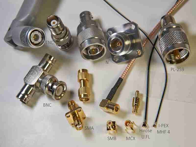
A lot of RF problems start with a simple assumption: “The connector looks right, so it should work.” In real projects, that is where trouble begins. Two RF connectors may look similar in photos, fit the same general cable family, and still perform very differently once the signal moves through the assembly. One version holds impedance better. Another introduces more reflection. A third may be mechanically acceptable but unstable after repeated mating, vibration, or outdoor exposure. For engineers, this means debugging time. For sourcing teams, it means delays, rework, and extra cost. For OEM factories, it can turn a routine cable order into a quality issue that shows up only after installation.
RF coaxial connector types are the standardized connector families used to terminate coaxial cable for RF signal transmission. The right choice depends on frequency range, impedance, cable structure, shielding continuity, mating style, space limits, and environmental demands. In practice, connectors such as SMA, BNC, N-Type, MMCX, and U.FL are selected not by name alone, but by how well they protect signal integrity and fit the real assembly.
At Sino-Conn, this is one of the most common gaps we see. A customer sends a part number, or sometimes only a photo, and asks whether we can make “the same one.” The answer is often yes in appearance, but the real work is confirming what “same” actually means: 50 ohm or 75 ohm, cable OD, shielding method, plating, temperature range, bend requirement, mating cycles, and whether the project needs the original connector or a flexible equivalent. That is why good RF work starts with connector selection, drawing confirmation, and clear specifications before production starts.
What Are RF Coaxial Connector Types?
In most RF systems, the connector is not just a mechanical part. It is part of the signal path, and even small differences in design can affect performance.
Its role is to carry high-frequency signals from one device to another while keeping the signal stable and consistent.

If the connector is not properly matched, the system may still work, but problems such as signal loss, reflection, or instability often appear during testing or actual use.
Where Are These RF Connectors Actually Used?
In real projects, RF coaxial connector types are used wherever signal integrity matters. That includes antennas, wireless modules, drones, medical devices, industrial control systems, and test equipment. The connector’s job is to maintain a clean electrical path while also providing a stable mechanical connection.
From a customer perspective, the key concerns are usually:
- Will the signal remain stable across the connection?
- Will the connector loosen, wear out, or fail over time?
- Can it handle the installation environment (vibration, temperature, bending)?
For example, in a drone application, a small connector may be required due to space limits. But if that connector cannot handle vibration or cable movement, signal loss can occur during flight. In medical equipment, even minor instability can affect measurement accuracy.
This is why connector selection is always tied to application, not just part number.
How Do RF Coaxial Connector Types Work?
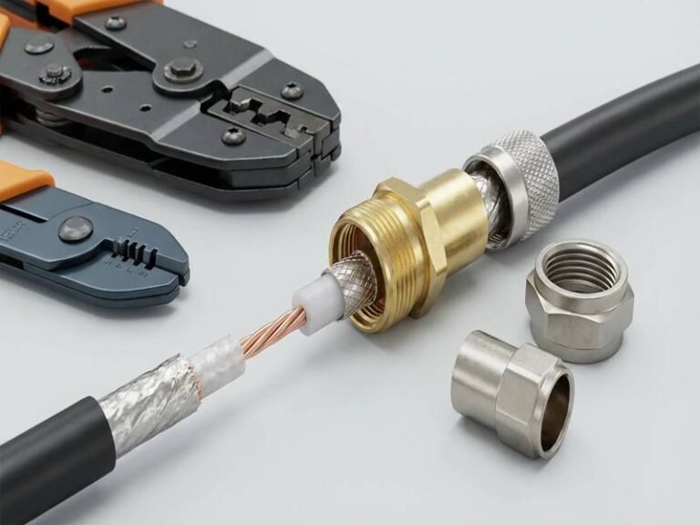
An RF coaxial connector works by extending the structure of the coaxial cable through the connection point. A typical coaxial cable includes:
- Inner conductor (signal path)
- Dielectric (insulation layer)
- Outer conductor (shield)
- Outer jacket (protection)

The connector must continue this structure as smoothly as possible. If the transition is not well controlled, problems can appear:
- Signal reflection (return loss increases)
- Power loss (insertion loss increases)
- EMI leakage or interference
One detail that is often overlooked is impedance continuity. Most RF systems use 50Ω or 75Ω. If the connector does not match the cable or system impedance, even a small mismatch can cause measurable signal degradation.
In practical terms, this is why two assemblies that look identical can behave differently. The internal structure—contact design, dielectric material, and how the connector is terminated to the cable—makes a significant difference.
Are RF Coaxial Connector Types Standard?
RF coaxial connector types follow standardized families such as SMA, BNC, and N-Type. These standards define basic dimensions, interface types, and general electrical behavior. That is why customers can specify connector names and expect a certain level of compatibility.
However, in actual sourcing and production, “standard” does not mean “identical.”
Differences can come from:
- Material quality (brass, stainless steel, plating thickness)
- Manufacturing tolerance
- Connector-to-cable matching
- Assembly process
For example:
| Factor | Impact on Performance |
|---|---|
| Poor plating quality | Higher resistance, shorter lifespan |
| Loose tolerance | Unstable connection |
| Incorrect cable match | Impedance mismatch |
| Weak assembly | Signal interruption under movement |
Another important point is the difference between original connectors and equivalent connectors.
- Original connectors: more consistent, higher cost, longer lead time
- Equivalent connectors: more flexible, faster supply, lower cost
In many commercial and industrial projects, equivalent connectors are widely used because they balance performance and cost effectively.
At Sino-Conn, both options are commonly discussed with customers. Some projects require original branded connectors due to certification or reliability requirements. Others prioritize faster delivery and cost control, where well-selected equivalents are a practical solution.
RF Coaxial Connector Types: What Customers Often Miss
Many issues do not come from choosing the wrong connector type, but from missing key details.
Common gaps we see:
- Customer provides only a photo without specifications
- Connector type is correct, but cable is mismatched
- Shielding requirement is unclear
- Installation conditions are not considered
A typical inquiry might look like this:
“I need this cable, same as the picture.”
From experience, that is only about 30% of the information needed.
To produce a reliable RF cable assembly, the following details are usually required:
| Category | Key Information |
|---|---|
| Electrical | Impedance, frequency range |
| Mechanical | Length, connector type, orientation |
| Cable | OD, flexibility, shielding |
| Environment | Temperature, bending, exposure |
| Compliance | UL, RoHS, REACH, etc. |
This is why drawing confirmation is critical.
At Sino-Conn, drawings are typically provided within 3 days, and in urgent cases, much faster. The purpose is not just documentation—it is to make sure the connector, cable, and structure all match the real application before production begins.
Why Connector Selection Is Often Underestimated
In many projects, connectors are treated as a small component compared to cables or devices. But in practice, they often determine whether the system performs as expected.
Some real-world observations:
- A well-designed cable can still fail due to poor connector termination
- Signal issues are often traced back to connector mismatch
- Installation problems are frequently caused by connector size or orientation
For OEM customers, this becomes more important because:
- Large quantities amplify small issues
- Rework costs increase quickly
- Delays affect entire production schedules
This is also why experienced teams focus on connector selection early in the project, not after problems appear.
What This Means in Real Projects
RF coaxial connector types are not interchangeable parts chosen by name alone. They are defined by how well they match the cable, the signal requirements, and the application environment.
A reliable selection process usually includes:
- Confirming electrical requirements (impedance, frequency)
- Matching connector to cable structure
- Checking mechanical constraints (space, bending, routing)
- Validating through drawings before production
When these steps are followed, most common RF issues can be avoided before they happen.
Which RF Coaxial Connector Types Are Most Used?
The RF coaxial connector types most people encounter in real projects are SMA, BNC, N-Type, MMCX, and U.FL (or U.FL-compatible). These are not just “popular names.” They cover most real-world needs—from compact devices to outdoor systems—because they balance frequency capability, size, durability, and ease of installation.
What matters is not memorizing the list, but understanding where each one actually works well and where it starts to cause problems.
Which RF Coaxial Connector Types Include SMA?
SMA is one of the most widely used RF connector types because it works across a broad range of applications without being too large.
Key characteristics:
- Impedance: 50Ω
- Typical frequency range: DC to 18 GHz (higher for precision versions)
- Threaded connection for stable contact
Where customers usually use SMA:
- RF modules
- antennas
- communication systems
- test equipment
Why engineers prefer SMA:
- Good balance between size and performance
- Stable connection under vibration
- Widely available globally
However, there are a few issues that show up often in actual projects:
- Mixing standard SMA with RP-SMA (they look similar but are not compatible)
- Using connectors not matched to the cable OD
- Choosing low-cost versions that loosen after repeated use
From experience, SMA works well when:
- Frequency is above 1 GHz
- Installation space is moderate
- The system requires stable performance over time
In projects where customers only provide photos, SMA is often identified quickly, but the real work is confirming the exact version (straight, right-angle, bulkhead, cable type). This is where drawing confirmation becomes necessary.
Which RF Coaxial Connector Types Include BNC?
BNC is known for its quick-connect design. It uses a bayonet locking mechanism, which allows fast installation and removal.
Key characteristics:
- Impedance: 50Ω or 75Ω
- Frequency: commonly used below 4 GHz (higher in specific setups)
- Easy to connect and disconnect
Where BNC is still widely used:
- video systems
- laboratory equipment
- testing setups
- legacy communication systems
Why customers choose BNC:
- Fast operation (no threading needed)
- Simple installation
- Lower cost compared to high-frequency connectors
The most common mistake with BNC is impedance mismatch.
There are two versions:
| Type | Application |
|---|---|
| 50Ω BNC | RF and test equipment |
| 75Ω BNC | video and broadcast |
They can physically connect, but electrically they are not interchangeable.
In real projects, this leads to:
- signal reflection
- unstable readings
- unexpected noise
Another limitation is frequency. BNC is not ideal for higher-frequency systems where SMA or other connectors perform better.
Which RF Coaxial Connector Types Include N-Type?
N-Type connectors are larger and designed for more demanding environments.
Key characteristics:
- Impedance: typically 50Ω
- Frequency: up to ~11 GHz (higher for precision versions)
- Strong threaded coupling
- Good weather resistance
Where N-Type is commonly used:
- outdoor antennas
- base stations
- industrial RF systems
Why customers choose N-Type:
- More robust mechanical structure
- Better performance in outdoor conditions
- Handles higher power levels
In many outdoor projects, the connector is exposed to:
- temperature changes
- moisture
- vibration
A smaller connector might work electrically but fail mechanically over time. N-Type reduces this risk.
Trade-offs:
- Larger size
- Requires more installation space
- Less suitable for compact devices
For industrial and infrastructure projects, reliability is often more important than size, which is why N-Type remains a common choice.
Which RF Coaxial Connector Types Are Mini (MMCX, U.FL)?
Miniature connectors are used when space is limited.
Two common types:
| Type | Size | Typical Use |
|---|---|---|
| MMCX | Small | embedded systems |
| U.FL | Very small | compact modules, drones |
Why customers choose them:
- Extremely compact
- Suitable for tight layouts
- Lightweight
Where they are used:
- drones
- wireless modules
- medical devices
- compact electronics
But these connectors come with limitations:
- Lower durability (limited mating cycles)
- More sensitive to cable pulling
- Higher risk of damage during installation
A common issue:
Customers choose U.FL to save space, but the cable is pulled during installation, causing:
- loose connection
- signal drop
- intermittent failure
In small-size RF projects, cable routing and strain relief become just as important as connector selection.
Which RF Coaxial Connector Types Support High Frequency?
As frequency increases, connector selection becomes more critical.
Common options for higher frequency:
- SMA (standard choice)
- precision SMA / 2.92mm connectors
- SMP / SMPM connectors
Important considerations:
- Not all connectors labeled “high frequency” perform equally
- Assembly quality becomes more important
- Cable and connector must be matched precisely
At higher frequencies:
- Small structural differences affect performance
- Tolerance control becomes critical
- Signal loss increases if not properly designed
A typical mistake:
Selecting a connector based on its maximum frequency rating without considering:
- actual operating frequency
- cable compatibility
- assembly method
In practice, many high-frequency issues come from:
- poor connector termination
- inconsistent assembly
- incorrect cable selection
This is why high-frequency applications often require custom cable assemblies, not just standard connectors.
RF Coaxial Connector Types Comparison (Quick Reference)
| Connector | Size | Frequency Range | Strength | Limitation |
|---|---|---|---|---|
| SMA | Medium | Up to 18 GHz+ | Stable, versatile | Requires proper matching |
| BNC | Medium | <4 GHz typical | Easy to use | Limited frequency |
| N-Type | Large | Up to ~11 GHz | Strong, outdoor use | Bulky |
| MMCX | Small | ~6 GHz | Compact | Lower durability |
| U.FL | Very small | ~6 GHz | Ultra compact | Fragile |
What This Means in Real Projects
Most connector issues do not come from choosing the wrong type. They come from:
- choosing based on appearance
- ignoring cable compatibility
- underestimating installation conditions
In many cases, customers start with:
“I need SMA” or “I need BNC”
But after reviewing the project, the real requirement may be:
- different connector orientation
- different cable type
- different shielding structure
This is why connector selection is rarely isolated. It is part of the entire cable assembly design.
When these factors are considered together early, projects move faster and avoid rework.
How Do You Choose the Right RF Connector?
Choosing RF coaxial connector types is not about picking a familiar name from a catalog. In real projects, the connector has to match the cable, the signal, and the installation conditions at the same time. If one of these three is ignored, problems usually show up later—during testing, installation, or after the product is already in use.
Most customers start with a simple question: “Which connector should I use?”
A more useful way to approach it is:
- What frequency am I working at?
- What cable am I using?
- What environment will this cable be installed in?
Once these are clear, the right connector type becomes much easier to define.
How to Match RF Coaxial Connector Types with Frequency?
Frequency is the first filter, but it is often oversimplified.
Many people look at the maximum frequency rating printed in a datasheet and assume that is enough. In practice, performance depends on how stable the signal is within your actual working range.
A more realistic selection approach looks like this:
| Working Frequency | Common Connector Choice | Notes |
|---|---|---|
| DC – 1 GHz | BNC / SMA | Cost-effective, stable |
| 1 – 6 GHz | SMA / MMCX | SMA preferred for stability |
| 6 – 18 GHz | SMA / N-Type (high spec) | Requires better assembly |
| >18 GHz | Precision connectors | Tight tolerance required |
Two points that matter in real use:
- A connector rated for 18 GHz does not guarantee stable performance at 18 GHz
- Assembly quality becomes more important as frequency increases
In one RF module project, the system operated at around 6 GHz. The customer initially chose a higher-grade connector expecting better performance. After testing, it turned out that a standard SMA assembly with proper cable matching provided the same performance at a lower cost.
This is why the actual operating frequency matters more than the maximum rating.
How to Match RF Coaxial Connector Types with Cable?
This is where many hidden issues come from.
Even if the connector type is correct, a mismatch with the cable can lead to:
- Poor termination quality
- Shielding gaps
- Mechanical instability
- Signal degradation
Important parameters to check:
- Cable outer diameter (OD)
- Dielectric material
- Shielding structure (braid, foil, or both)
- Flexibility and bending requirement
Example:
| Cable Type | Typical Connector Match |
|---|---|
| RG-178 / RG-316 | SMA, MMCX |
| Micro coax (≤1.5mm) | U.FL, MMCX |
| Large coax (>5mm) | N-Type |
A real issue we often see is using a connector designed for a thicker cable on a thinner cable. The result may look acceptable after assembly, but under vibration or movement, the connection becomes unstable.
In practice, connector and cable should always be treated as a pair.
This is why, when customers provide only a connector type, the next step is always to confirm the cable details before moving forward.
How to Choose RF Coaxial Connector Types for Space?
Space constraints often determine whether a design is practical.
Even when the electrical selection is correct, installation can fail if:
- The connector is too large
- Cable cannot bend properly
- There is no room for proper routing
Typical selection based on space:
| Installation Space | Recommended Connector |
|---|---|
| Very tight | U.FL / MMCX |
| Medium | SMA |
| Large / open area | N-Type |
Key considerations:
- Straight vs right-angle connectors
- Minimum bending radius of the cable
- Connector orientation relative to the device
In compact products such as drones or medical devices, space is limited and cable routing is critical. A slightly larger connector can block assembly or create stress points on the cable.
Mini connectors solve space problems but introduce other risks:
- Lower mechanical strength
- Sensitive to pulling force
- Limited mating cycles
This trade-off needs to be evaluated early in the design.
How to Ensure RF Coaxial Connector Types EMI Shielding?
Shielding is often treated as a cable feature, but the connector plays a major role in maintaining shielding continuity.
If the connector is not properly matched or assembled, the shielding path can be interrupted, leading to:
- EMI leakage
- External interference
- Reduced signal quality
Common shielding structures:
| Shield Type | Performance Level |
|---|---|
| Single braid | Basic |
| Foil + braid | High |
| Double braid | Very high |
However, shielding performance depends on how the connector is integrated with the cable.
Typical issues include:
- Shield not properly connected to connector body
- Incomplete grounding
- Poor termination
A frequent request is:
“Can you add shielding to this cable?”
Without defining:
- How shielding connects to the connector
- Whether full shielding continuity is required
the result may not meet expectations.
In projects that require stable signal performance, shielding design should be confirmed as part of the connector selection process, not added later.
How to Choose Based on Real Project Conditions?
Beyond technical parameters, practical conditions often influence the final decision.
Key factors include:
- Installation environment (indoor vs outdoor)
- Temperature range
- Exposure to oil, UV, or chemicals
- Required flexibility
- Expected lifespan
Example comparison:
| Condition | Connector Preference |
|---|---|
| Outdoor / harsh environment | N-Type |
| Frequent connection/disconnection | SMA or BNC |
| Compact electronics | MMCX / U.FL |
| High reliability system | SMA / N-Type |
In one industrial project, the initial design used a smaller connector to save space. After reviewing the environment (vibration + outdoor exposure), the connector was changed to a more robust type. This improved long-term reliability and reduced maintenance.
What This Means in Real Projects
Choosing RF coaxial connector types is not about selecting a familiar name. It comes down to how well the connector, cable, and application conditions match together.
In most cases, stable performance depends on:
- Matching the connector to the correct cable structure
- Confirming impedance and frequency requirements
- Considering installation space and routing
- Ensuring proper shielding continuity
When these factors are defined early, most common RF issues can be avoided before production even starts.
Do You Need a Custom RF Cable Assembly?
Standard RF coaxial connector types work well when the application is simple and the cable assembly follows common specifications. But in many real projects, especially in OEM production, medical devices, drones, and industrial equipment, standard solutions often fall short.

The question is not whether custom is “better.” The real question is whether your project can meet performance, installation, and reliability requirements using off-the-shelf parts.
In practice, a large portion of RF cable issues come from trying to force a standard connector and cable into a design that requires more flexibility.
When Are Standard RF Coaxial Connector Types Not Enough?
Standard solutions start to show limitations when the project moves beyond basic configurations.
Typical situations where problems appear:
- Cable length is not standard
- Connector orientation does not fit installation space
- Cable is too stiff or too thick
- Shielding performance is not sufficient
- Assembly must withstand vibration or movement
A common scenario:
A customer selects a standard SMA cable assembly from the market. Electrically it works, but during installation:
- The cable cannot bend properly
- The connector position is not aligned
- Stress is applied to the connector
After some time, the connection becomes unstable.
Another case involves customers sending only product images and asking for the same cable. The visible parts may be easy to copy, but hidden details such as impedance, shielding structure, and material are missing. Without those, a “similar-looking” product may not perform the same.
This is where standard products stop being practical.
How Can Custom RF Coaxial Connector Types Help?
Custom RF cable assemblies allow the connector and cable to be designed together instead of being selected separately.
This approach improves:
- Electrical stability
- Mechanical fit
- Long-term reliability
Instead of adapting your design to available products, customization adapts the product to your design.
Key improvements from customization:
- Correct connector-to-cable matching
- Optimized shielding structure
- Controlled cable flexibility and routing
- Reduced mechanical stress during installation
In many cases, the difference is not visible from the outside. But once installed, the system behaves more consistently.
For example, in one compact device project, the standard cable caused excessive bending near the connector. By adjusting the cable structure and connector orientation, the assembly fit naturally into the design, reducing stress and improving durability.
What Can Be Customized in RF Coaxial Connector Types?
Customization goes beyond cable length. It includes multiple aspects of the cable assembly.
Electrical parameters:
- Impedance (50Ω / 75Ω)
- Shielding level (single, double, or combined)
- Signal path optimization
Mechanical structure:
- Cable length (from 1 piece, no MOQ)
- Connector type and orientation (straight, right-angle, bulkhead)
- Strain relief or overmolding
Material selection:
- Jacket material (PVC, TPE, FEP, etc.)
- High-temperature resistance
- Oil, UV, or chemical resistance
- Halogen-free or special compliance requirements
Connection definition:
- Pinout
- End-to-end wiring logic
- Connector combinations
In many RF projects, the combination of these factors determines whether the product can be installed easily and perform reliably over time.
How Custom RF Coaxial Connector Types Are Developed
A structured process helps reduce uncertainty and avoid rework.
Typical steps:
- Review requirements (drawing, part number, or sample)
- Confirm missing parameters (cable, impedance, environment)
- Create drawing (CAD to PDF)
- Customer approval
- Sample production
- Mass production
Key point:
Problems are easier to fix at the drawing stage than after production.
At Sino-Conn, drawings are usually completed within about 3 days. For urgent projects, initial drawings can be prepared much faster. This allows customers to verify details early and avoid delays.
Original vs Equivalent Connectors in Custom Projects
When building custom assemblies, customers often need to decide between original branded connectors and equivalent alternatives.
Each option has its place:
| Option | Advantage | Limitation |
|---|---|---|
| Original connector | Consistent quality, brand assurance | Higher cost, longer lead time |
| Equivalent connector | Lower cost, faster supply | Requires validation |
In many commercial and industrial applications, equivalent connectors are widely used because they provide a good balance between performance and cost.
In projects with strict certification or reliability requirements, original connectors may still be necessary.
The choice depends on:
- Application requirements
- Budget
- Delivery timeline
What This Means in Real Projects
Custom RF coaxial connector types are not always required, but they become important when standard products cannot meet the full set of project requirements.
In most cases, customization is beneficial when:
- Installation space is limited
- Cable routing is complex
- Performance needs are specific
- Standard products create mechanical or electrical compromises
A practical approach is:
- Start with the standard connector type
- Evaluate whether it fits the cable and installation
- Adjust through customization if needed
This reduces both cost and risk.
How Sino-Conn Supports Custom RF Cable Assemblies
In real sourcing situations, speed and flexibility often matter as much as technical capability.
Sino-Conn supports custom RF cable projects by focusing on:
- Fast response and clear communication
- Drawing confirmation before production
- Flexible connector sourcing (original and equivalent)
- No minimum order quantity
- Stable production with full inspection
Typical capability:
| Stage | Lead Time |
|---|---|
| Drawing | 30 minutes – 3 days |
| Sample | 2–3 days (urgent) / 2 weeks |
| Mass production | 2–4 weeks |
Customers approach projects differently:
- Engineers focus on feasibility and performance
- OEM factories focus on cost and delivery
- Trading companies focus on matching specifications quickly
A flexible approach helps address all three.
When requirements are clear early, projects move faster and require fewer adjustments later.
What Affects RF Connector Cost?
When customers compare RF cable prices, the connector name is usually the first thing they look at. In reality, that is only a small part of the cost.
Most of the price comes from how the cable assembly is built—connector choice, cable structure, material requirements, and the level of processing involved.
Two assemblies may look almost the same in photos, but once the full specifications are confirmed, the cost can be very different. The gap usually comes from details that are easy to miss at the beginning, such as material selection, tolerance control, shielding design, and connector sourcing.
This is why price often changes after specification confirmation. When these factors are defined early, it becomes much easier to keep the project within budget and avoid unexpected adjustments later.
What Are Original vs Equivalent RF Coaxial Connector Types?
One of the biggest cost differences comes from the choice between original connectors and equivalent alternatives.
Original connectors:
- Higher unit price
- Longer lead time (sometimes several weeks)
- Strong brand consistency
- Required in certain industries (medical, defense)
Equivalent connectors:
- Lower cost (often 20%–50% lower)
- Faster availability
- Flexible sourcing
- Suitable for most commercial and industrial projects
Comparison:
| Option | Cost Level | Lead Time | Typical Use |
|---|---|---|---|
| Original | High | Longer | Certified or high-reliability systems |
| Equivalent | Medium–low | Short | OEM, industrial, commercial |
In real projects, many customers initially request original connectors based on part numbers. After reviewing pricing and delivery timelines, they often consider equivalent options, especially when performance requirements allow it.
This is not just about saving cost. It also affects delivery schedules. When connectors are not in stock, waiting for original parts can delay the entire project.
Providing both options early in the quotation stage helps customers make practical decisions based on their priorities.
How Specs Affect RF Coaxial Connector Types Price?
Specifications have a direct and sometimes large impact on cost.
The main drivers include:
- Cable material
- Shielding structure
- Connector plating quality
- Temperature and environmental requirements
For example:
| Specification | Cost Impact |
|---|---|
| Standard PVC cable | Base cost |
| FEP or high-temp cable | +15% to +40% |
| Double shielding | +10% to +30% |
| Special compliance materials | +20% to +60% |
A common situation is over-specification.
Customers sometimes request:
- High-temperature materials without needing them
- Maximum shielding when moderate shielding is enough
- Premium plating where standard plating would work
These choices increase cost without improving actual performance in the application.
A more effective approach is to match specifications to real working conditions. When the environment and requirements are clearly defined, unnecessary cost can be avoided.
How Cable Structure Impacts RF Coaxial Connector Types Cost?
The cable itself is often a major part of the total cost.
Important factors:
- Cable diameter (OD)
- Number of shielding layers
- Flexibility requirements
- Reinforcement (Kevlar, special cores)
Example:
| Cable Structure | Cost Impact |
|---|---|
| Single shield coax | Base |
| Double shield coax | +10% to +25% |
| Micro coax (precision) | +20% to +50% |
| High-flex cable | +15% to +35% |
In compact designs such as drones or medical devices, micro coax cables are often required. These cables are more difficult to manufacture and assemble, which increases cost.
Another factor is flexibility. Cables designed for repeated bending or tight routing usually require different materials and construction, which also affects pricing.
How Lead Time Impacts RF Coaxial Connector Types Cost?
Lead time and cost are closely linked.
Shorter lead times often require:
- Priority production scheduling
- Faster material sourcing
- Air freight instead of standard shipping
Typical timelines:
| Stage | Standard Time | Urgent Option |
|---|---|---|
| Drawing | 3 days | Same day possible |
| Sample | 2 weeks | 2–3 days |
| Mass production | 3–4 weeks | ~2 weeks |
Urgent orders usually increase cost due to:
- Overtime production
- Expedited material procurement
- Faster logistics
On the other hand, flexible timelines allow for:
- Better material sourcing
- More efficient production planning
- Lower overall cost
Balancing time and cost is an important part of project planning.
How Order Quantity Affects RF Coaxial Connector Types Cost?
Quantity has a direct impact on unit price.
Typical trends:
- Small quantity (samples or prototypes): higher unit cost
- Medium quantity: balanced pricing
- Large quantity: lower unit cost due to scale
Example:
| Quantity Level | Cost Trend |
|---|---|
| 1–50 pcs | Highest per unit |
| 100–1000 pcs | Moderate |
| 5000+ pcs | Lower per unit |
However, flexibility is also important.
In many projects, customers need:
- Small batches for testing
- Gradual scaling to mass production
Having the option to start with low quantities helps reduce risk during development.
How Application and Region Affect RF Coaxial Connector Types Cost?
Cost also varies depending on application and market.
Industry differences:
| Industry | Cost Level |
|---|---|
| Medical / military | High |
| Industrial | Medium |
| Consumer electronics | Lower |
Reason:
- Higher certification requirements
- Stricter quality control
- More complex specifications
Regional differences:
| Region | Cost Trend |
|---|---|
| USA | Higher |
| Europe (DE/FR) | Higher |
| Japan | Medium–high |
| Southeast Asia / India | Lower |
These differences are influenced by:
- Quality expectations
- Certification requirements
- Market pricing levels
Understanding the target market helps define the right cost structure.
What This Means in Real Projects
Cost is not a single number decided at the end. It is built step by step based on design choices.
In most RF cable projects, cost can be optimized by:
- Choosing the right connector type for the application
- Matching cable specifications to actual requirements
- Considering equivalent connectors where appropriate
- Planning realistic lead times
A practical approach is to define priorities early:
- Is performance the highest priority?
- Is delivery time critical?
- Is cost the main concern?
When these priorities are clear, it becomes easier to balance cost and performance without unnecessary compromises.
In many cases, a well-balanced solution saves more money than simply choosing the lowest initial price.
How Can You Avoid Common RF Connector Mistakes?
Most RF connector problems do not come from complex engineering challenges. They come from small decisions made early—choosing by appearance, skipping specification checks, or assuming one connector works the same as another. These issues usually do not show up immediately. They appear during testing, installation, or after the product is already in use.
Avoiding mistakes is less about advanced theory and more about following a clear process and paying attention to details that are easy to overlook.
Are You Choosing RF Coaxial Connector Types by Look?
This is one of the most common mistakes.
A connector is selected based on a photo or visual similarity, without confirming the actual specifications. Two connectors may look identical externally but differ in:
- Impedance (50Ω vs 75Ω)
- Internal structure
- Contact design
- Cable compatibility
Typical scenario:
- Customer sends a picture
- Supplier identifies it as SMA or BNC
- Production starts without full confirmation
What happens next:
- Connector fits physically
- Signal performance is unstable
- System does not pass testing
The issue is not visible from the outside.
A better approach is to confirm:
- Connector type (exact version)
- Impedance
- Cable type and size
- Application requirements
In many RF cable projects, visual matching is only the starting point. Specification matching is what determines performance.
Do RF Coaxial Connector Types Cause Signal Loss?
Yes, and often in ways that are not immediately obvious.
Signal loss is usually caused by small mismatches in the system. These include:
- Impedance mismatch
- Poor connector-to-cable transition
- Inconsistent assembly quality
Typical issues and their effects:
| Issue | Result |
|---|---|
| 50Ω cable with 75Ω connector | Signal reflection |
| Poor crimping or soldering | Intermittent signal |
| Weak shielding connection | EMI interference |
| Low-quality connector material | Increased resistance |
In many cases, the system works during initial testing but becomes unstable over time. This is especially common in:
- High-frequency applications
- Systems with vibration
- Long cable runs
Signal loss is not always caused by the connector type itself. It is often caused by how the connector is selected and assembled.
Are RF Coaxial Connector Types Missing Specs?
Incomplete specifications are one of the main reasons for delays and rework.
A typical RF inquiry may include:
- Connector type
- Cable length
But miss critical details such as:
- Cable structure
- Shielding requirement
- Operating environment
- Connector orientation
Without these, several problems can occur:
- Incorrect quotation
- Multiple design revisions
- Delayed production
Example:
| Missing Info | Possible Problem |
|---|---|
| Cable OD not defined | Connector mismatch |
| Shielding not specified | EMI issues |
| Environment unknown | Material failure |
| Orientation unclear | Installation difficulty |
This is why converting requirements into a drawing is important.
Once a drawing is created and confirmed, most misunderstandings are removed before production starts.
How to Confirm RF Coaxial Connector Types Before Production?
A structured confirmation process reduces risk significantly.
Typical steps:
- Review requirements
- Confirm connector and cable compatibility
- Create technical drawing (CAD → PDF)
- Customer approval
- Sample validation
- Mass production
This process helps identify:
- Design issues
- Installation problems
- Performance risks
In many projects, skipping this step leads to:
- Rework
- Increased cost
- Delays in delivery
Providing a drawing early makes expectations clear on both sides.
At Sino-Conn, drawings are usually completed within a few days, and in urgent cases much faster. This allows customers to review and confirm details before production begins.
Are You Ignoring Installation Conditions?
A connector that works in a lab may fail in real use.
Installation conditions affect performance more than many expect.
Key factors:
- Vibration
- Temperature
- Cable movement
- Space constraints
Example:
| Condition | Risk |
|---|---|
| Tight bending | Cable damage |
| Constant vibration | Loose connection |
| Outdoor exposure | Material degradation |
| Limited space | Incorrect installation |
A connector selected without considering these factors may:
- Wear out faster
- Lose contact stability
- Cause signal interruption
In many industrial and outdoor applications, choosing a slightly larger or more robust connector improves long-term reliability.
Are You Overlooking Assembly Quality?
Even with the correct connector and cable, poor assembly can cause failure.
Common assembly issues:
- Incorrect crimping
- Inconsistent soldering
- Improper shielding termination
- Lack of strain relief
These issues often result in:
- Intermittent signal
- Reduced lifespan
- Higher failure rates
Quality control is critical.
Typical inspection points include:
- Electrical testing
- Visual inspection
- Mechanical pull testing
In many projects, assembly quality has a greater impact than connector selection itself.
What This Means in Real Projects
Most RF connector problems can be avoided with a few practical steps:
- Do not rely on appearance alone
- Confirm full specifications early
- Match connector and cable properly
- Consider installation conditions
- Validate design before production
When these steps are followed, the connector becomes a stable part of the system instead of a source of issues.
In many cases, the difference between a smooth project and repeated delays comes down to how early these details are addressed.
Ready to Customize Your RF Coaxial Connector Types?
If you are working on an RF project, choosing the right connector is only part of the solution. What really matters is how the connector, cable, and assembly work together in your actual application.
At Sino-Conn, we support:
- Full specification review (connector + cable)
- Fast drawing support (as fast as 30 minutes)
- Flexible customization (length, pinout, materials, structure)
- No MOQ (starting from 1 piece)
- Fast sampling (2–3 days available)
- Stable production with full inspection (3-stage quality control)
Whether you have:
- A complete drawing
- A part number
- Or just a product photo
We can help you turn that into a reliable RF cable assembly.
Send us your requirement, and we will provide:
- Technical review
- Optimized solution
- Accurate quotation
A good RF connection starts with the right decision.