Skip to content
In medical equipment, connector selection is rarely a small detail. It affects signal quality, cleaning resistance, mechanical life, patient safety, serviceability, and even whether a project can pass internal verification without repeated redesign. Many device problems that appear to be caused by software, PCB layout, or sensors are later traced back to unstable contacts, poor shielding, insufficient strain relief, or a connector that was never truly matched to the cable structure. This happens often in patient monitoring systems, imaging equipment, handheld devices, wearable devices, and surgical tools, where cables are bent repeatedly, signals are sensitive, and space is limited. A connector that looks acceptable on a drawing may still fail in the real product because the mating force is wrong, the cable exits at the wrong angle, the shielding is incomplete, or sterilization chemicals attack the housing material over time.
A medical connector is a high-reliability interface used in healthcare equipment to transmit power, signals, or data safely and consistently. The right medical connector must match the electrical requirements, cable structure, environmental conditions, cleaning method, mating life, size limits, and regulatory expectations of the device. In practice, choosing the right one means looking at the full cable assembly, not just the connector part number.
This is why engineers and sourcing teams often come to a manufacturer with only a model number, a sample photo, or a device picture and ask a simple question: can you make the same one, or can you make it better? In many cases, the real answer only becomes clear after the connector, cable, shielding, pinout, material, and application are reviewed together. That is where a medical cable assembly project stops being a catalog purchase and becomes an engineering decision.
What Is a Medical Connector?
A medical connector is not just a component that links a cable to a device. In real projects, it is a critical interface that determines whether your medical equipment can deliver stable signals, safe power transmission, and long-term reliability under continuous use.

In practical terms, a medical connector is used to connect cables to:
- Patient monitoring devices (ECG, EEG, SpO2)
- Medical imaging systems (ultrasound, CT modules)
- Surgical equipment
- Wearable and portable healthcare devices
Unlike standard connectors, medical connectors must perform consistently under frequent bending, repeated plugging, strict hygiene conditions, and sensitive signal environments. This is why many projects that look simple at the beginning become complex once testing starts.
What defines a medical-grade connector?
A medical-grade connector is defined by how it performs in real use, not by how it looks or its part number.
From actual project experience, customers usually care about four key areas:
1. Signal stability (most critical factor)
In medical devices, especially monitoring and imaging systems, signals are often weak or high-speed. Any instability in the connector can lead to:
- Noise in ECG/EEG signals
- Image distortion in ultrasound systems
- Data loss in high-speed transmission
Typical requirement range:
| Parameter | Typical Medical Requirement |
|---|---|
| Contact resistance | ≤ 30 mΩ |
| Insulation resistance | ≥ 1000 MΩ |
| Withstanding voltage | 300–1000V |
| Shielding effectiveness | ≥ 60 dB |
Even small deviations can affect device performance. This is why connector selection must consider the full signal path, not just physical fit.
2. Mechanical durability (real-world usage impact)
Medical cables are rarely static. In real hospital environments:
- Cables are bent hundreds to thousands of times
- Devices are moved between rooms
- Connectors are plugged/unplugged daily
Typical durability expectations:
| Item | Typical Requirement |
|---|---|
| Mating cycles | 1,000 – 10,000 times |
| Bend cycles | 5,000 – 50,000 times |
| Pull force | 30–100 N |
The failure point is often not the connector itself, but the transition area between connector and cable.
At Sino-Conn, we often improve this by:
- Reinforced strain relief design
- Optimized overmolding structure
- Flexible cable material matching
3. Material performance (environment matters)
Medical connectors must handle specific environments:
- Regular cleaning (alcohol, disinfectants)
- Temperature variation
- Long-term usage
Common material requirements include:
- Flame resistance
- Corrosion resistance
- UV resistance (for some devices)
- Halogen-free / PFAS-free
For example, in one monitoring cable project, a customer experienced cracking issues after several months. The root cause was not the connector design, but the incorrect jacket material selection.
4. Precision and compatibility (fit is not enough)
Many customers come with a request like:
“We need the same connector as this”
However, the key questions are:
- Is the pin definition identical?
- Is shielding terminated correctly?
- Does the connector match the cable structure?
A connector may look identical but still fail due to:
- Different internal structure
- Different contact plating
- Different tolerance
At Sino-Conn, we always confirm:
- Pinout mapping
- Connector dimensions
- Cable OD compatibility
before production.
What materials and standards are required?
Material and compliance are often where projects become delayed if not clarified early.
In real business scenarios, customers usually need specification sheets that include:
- Dimensions
- Electrical parameters
- Material description
- Shielding structure
- Cable OD and flexibility
- Temperature range
Common compliance requirements:
| Standard | Why Customers Need It |
|---|---|
| UL | Electrical safety (especially US market) |
| ROHS | Environmental compliance |
| REACH | Chemical safety |
| ISO 9001 | Quality system |
| PFAS-free | Increasing regulatory requirement |
| COC / COO | Import/export documentation |
Key insight:
Not all projects require the highest level of certification.
For example:
- A prototype project may not require full certification
- A mass production project for US market likely requires UL
At Sino-Conn, we help customers balance:
- Compliance level
- Cost
- Lead time
This avoids:
- Over-specification (unnecessary cost)
- Under-specification (project risk)
What makes medical connectors different from industrial connectors?
Many customers initially think industrial connectors can be used in medical devices. In some cases, they can — but the requirements are usually higher in medical applications.
Key differences in real use:
| Factor | Medical Connector | Industrial Connector |
|---|---|---|
| Signal stability | Very high | Medium |
| EMI shielding | Critical | Optional |
| Flexibility | High | Medium |
| Cleaning resistance | Required | Not required |
| Size constraints | Strict | More flexible |
Failure impact difference:
- Industrial device → downtime
- Medical device → incorrect data or unsafe operation
Example from real project:
A customer used an industrial connector for a monitoring device to reduce cost.
Result:
- Signal noise increased
- Device readings became unstable
After switching to a properly shielded medical connector:
- Signal stabilized
- Product passed testing
This is why connector selection in medical projects should not be based on price alone.
Practical takeaway for buyers and engineers
From real project experience, the most common mistakes are:
- Choosing connector before defining cable
- Ignoring shielding design
- Copying existing product without understanding structure
- Focusing only on price
Correct approach:
- Define application (monitoring / imaging / wearable)
- Confirm signal type (low-level / high-speed / power)
- Match cable structure
- Select connector accordingly
- Confirm drawing before production
At Sino-Conn, we support this process by:
- Reviewing customer requirements (even from just a photo)
- Providing drawing within 30 minutes to 3 days
- Supporting no MOQ (even 1 piece)
- Offering both original and alternative connector solutions
A medical connector may look like a small component, but in real projects, it often determines whether your product works reliably or fails during testing.
Understanding it correctly at the beginning will save significant time, cost, and risk later.
Which Types of Medical Connectors Are Common?
In real medical cable assembly projects, connector selection is not about how many types exist in the market. It is about which connector actually works reliably in your specific device.
From practical experience, most medical projects repeatedly use a limited group of connector types. The difference is not the category itself, but how well the connector is matched with:
- Signal type (low-level / high-speed / power)
- Cable structure (shielding, OD, flexibility)
- Device layout (space, routing, movement)
- Usage frequency (plugging cycles, bending)
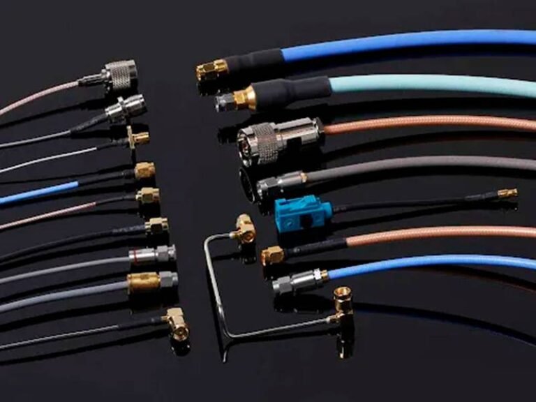
Below are the most commonly used connector types in medical applications, along with how they are used in real projects.
Circular connectors (reliable and widely used)
Circular connectors are one of the most commonly used types in medical devices because of their stable connection, strong mechanical structure, and versatility.

They are widely used in:
- Patient monitoring equipment
- Medical carts and portable devices
- Power + signal combined cables
Typical characteristics:
| Parameter | Typical Range |
|---|---|
| Pin count | 2 – 30+ pins |
| Mating cycles | 1,000 – 5,000 |
| Locking method | Threaded / push-lock |
| Cable OD | 3 – 8 mm |
Why customers choose circular connectors:
- Strong mechanical retention
- Easy to align and connect
- Suitable for medium to high cable OD
- Good for mixed signal + power applications
Common mistake:
Customers sometimes choose circular connectors that are too large for their device, which causes:
- Space issues
- Cable routing problems
- Unnecessary cost increase
At Sino-Conn, we often help customers:
- Reduce connector size
- Optimize pin configuration
- Improve cable exit direction
This can significantly improve product design without changing core functionality.
Push-pull connectors (fast connection, high-end applications)
Push-pull connectors are widely used in medical environments where quick and secure connection is required.

They are commonly found in:
- Surgical devices
- High-end monitoring systems
- Portable medical equipment
Typical characteristics:
| Parameter | Typical Range |
|---|---|
| Mating cycles | 5,000 – 10,000 |
| Locking method | Push-pull |
| Size | Compact |
| Application level | Medium to high-end |
Why customers choose push-pull connectors:
- Quick connection and disconnection
- Secure locking (prevents accidental unplugging)
- Compact size
- Professional appearance
Real-world consideration:
Push-pull connectors are often more expensive.
In many OEM projects, customers ask:
“Can we replace this with a lower-cost solution?”
In some cases, yes — but only if:
- Mechanical requirements allow
- User operation does not require fast release
At Sino-Conn, we usually provide:
- Original push-pull solution
- Cost-optimized alternative
So customers can compare based on:
- Budget
- performance
- lead time
Coaxial and micro-coax connectors (for imaging and high-speed signals)
These connectors are critical in applications where signal integrity directly affects device performance.

They are widely used in:
- Ultrasound systems
- Imaging modules
- High-speed data transmission
Typical characteristics:
| Parameter | Typical Range |
|---|---|
| Impedance | 50Ω / 75Ω |
| Frequency range | Up to GHz level |
| Cable type | Coax / micro-coax |
| Shielding | High |
Why customers choose coaxial connectors:
- Stable high-frequency transmission
- Low signal loss
- Strong EMI shielding
Key technical requirement:
Connector must match:
- Cable impedance
- Shielding structure
- Signal path continuity
Common issue:
- Connector mismatch → signal reflection
- Poor shielding → noise / data loss
At Sino-Conn, we often support:
- Micro-coax cable assemblies
- High-density connector integration
- Custom shielding solutions
Many projects start with:
- A photo
- A sample
- Or a rough description
We then help define:
- Exact connector type
- Cable structure
- Assembly design
Snap connectors (for ECG and patient monitoring)
Snap connectors are commonly used in patient monitoring systems, especially ECG cables.
Typical characteristics:
| Parameter | Typical Range |
|---|---|
| Application | ECG / electrode |
| Size | Small |
| Connection type | Snap |
| Signal type | Low-level |
Why customers choose snap connectors:
- Easy to connect to electrodes
- Lightweight
- Low cost
- Suitable for disposable or semi-reusable systems
Critical requirement:
Because signals are very weak:
- Contact stability is essential
- Shielding must be properly designed
Common problem:
- Poor contact → signal noise
- Weak shielding → unstable readings
At Sino-Conn, we optimize:
- Contact quality
- Shielding structure
- Cable flexibility
to ensure stable signal performance.
Board-to-board and internal connectors (compact devices)
These connectors are used inside devices where space is limited.
Common in:
- Portable devices
- Wearable medical products
- Compact monitoring units
Typical characteristics:
| Parameter | Typical Range |
|---|---|
| Pitch | 0.3 – 1.0 mm |
| Pin count | High density |
| Application | Internal connection |
Why customers choose these connectors:
- Small size
- High pin density
- Suitable for compact design
Key challenge:
- Assembly precision
- Signal integrity
- Cable-to-board transition
At Sino-Conn, we help customers:
- Match cable to connector
- Define pinout correctly
- Ensure stable assembly
Custom hybrid connectors (power + signal combined)
Many modern medical devices require both power and signal in one connector.
Typical use cases:
- Imaging systems
- Portable medical devices
- OEM integrated systems
Typical characteristics:
| Feature | Description |
|---|---|
| Function | Power + signal |
| Pin design | Custom |
| Structure | Hybrid |
| Complexity | High |
Why customization is needed:
Standard connectors often cannot:
- Fit space constraints
- Support mixed signals
- Match device layout
Typical customization options:
- Pin definition
- Cable length
- Connector housing
- Shielding structure
At Sino-Conn:
- No MOQ (even 1 piece)
- Drawing support before production
- Flexible customization
Key insight:
Over 60–70% of medical cable projects involve:
- Modified connectors
- Custom assemblies
Practical selection guide
To simplify selection, customers can use this quick reference:
| Application | Recommended Connector Type |
|---|---|
| ECG / monitoring | Snap / small circular |
| Imaging | Coax / micro-coax |
| Surgical device | Push-pull |
| Portable device | Circular / custom |
| Wearable | Custom small connectors |
Final takeaway:
There is no “best connector”
only the most suitable one for your application.
In real projects, success comes from:
- Matching connector + cable together
- Understanding actual usage conditions
- Confirming design before production
At Sino-Conn, we support customers from:
- Concept stage
- Sample development
- Mass production
Most projects do not start with full specifications.
They start with a question:
“Can you make something like this?”
And from there, the right connector solution is built step by step.
How to Choose the Right Medical Connector?
Choosing a medical connector is rarely a one-step decision. In real projects, the connector only works well when it is selected together with the cable, the device layout, and the actual use environment. Many problems such as unstable signals, short cable life, or repeated redesign do not come from the connector model itself, but from a mismatch between connector, cable, and application.
From practical experience, a reliable selection process should always cover five key areas at the same time:
- Signal type and electrical performance
- Cable structure and outer diameter
- Mechanical stress and usage frequency
- Environmental conditions (cleaning, temperature, chemicals)
- Supply factors (lead time, cost, availability)
Ignoring any one of these can cause failure during testing or after product launch.
How to match connector with cable specifications?
The connector and cable must always be treated as one system. Selecting them separately is one of the most common reasons for project delays.
1. Start from signal type, not connector model
Different signals require different connector structures:
| Signal Type | Typical Requirement | Connector Direction |
|---|---|---|
| ECG / EEG (low-level) | Low noise, stable contact | Shielded, low-resistance connectors |
| Imaging / high-speed | Controlled impedance | Coax or high-density connectors |
| Power supply | High current capacity | Larger pin / circular connectors |
| Hybrid (power + signal) | Separation + shielding | Multi-pin custom connectors |
If signal type is not defined clearly:
- Connector may work physically
- But fail electrically
2. Match cable OD with connector entry
Cable outer diameter (OD) must fit the connector properly.
| Cable OD | Recommended Connector Range |
|---|---|
| 1.0–2.0 mm | Micro connectors |
| 2.0–4.0 mm | Small circular / compact |
| 4.0–7.0 mm | Standard circular |
Common issues we see:
- Cable too soft → slips or weak retention
- Cable too thick → stress on termination
- Wrong strain relief → early failure
At Sino-Conn, we always check:
- Cable OD vs connector entry
- Jacket hardness vs retention
- Strain relief design
before confirming production.
3. Confirm pin definition (pinout) carefully
This is one of the most critical steps.
Many customers say:
“We need the same cable”
But in reality:
- Pin definitions may be different
- Grounding may not be the same
- Shield termination may be missing
Typical pinout risks:
| Issue | Result |
|---|---|
| Wrong pin mapping | Device malfunction |
| Mixed signal/power | Signal interference |
| Incorrect grounding | Noise / instability |
At Sino-Conn:
- All projects require pinout confirmation
- CAD drawing is provided before production
- Customer approval is mandatory before manufacturing
This avoids costly rework.
How to consider EMI shielding and signal integrity?
In medical devices, EMI is one of the most underestimated risks.
Especially in:
- Patient monitoring systems
- Imaging equipment
- Multi-signal devices
Even small interference can cause:
- Noise in ECG signals
- Unstable readings
- Data transmission errors
Common shielding structures:
| Shield Type | Performance | Typical Use |
|---|---|---|
| Foil shield | Basic | Simple monitoring |
| Braided shield | Medium | General medical devices |
| Foil + braid | High | Imaging / critical signals |
Key design requirements:
- Shield must be continuous from cable to connector
- Proper grounding must be ensured
- Connector housing may need conductive design
Real project example:
A customer had unstable monitoring signals.
Problem analysis showed:
- Shield was not properly terminated at connector
After redesign:
- Noise reduced significantly
- Signal became stable
Important detail often ignored:
Connector alone cannot solve EMI
→ It must work together with cable shielding
At Sino-Conn, we design:
- Shield termination structure
- Grounding path
- Connector integration
as one system.
How to choose between original and alternative connectors?
This is a very practical decision in real projects.
Customers usually consider:
- Cost
- Lead time
- Availability
Comparison:
| Type | Advantages | Limitations |
|---|---|---|
| Original connectors | High reliability, brand recognition | High cost, long lead time |
| Alternative connectors | Lower cost, faster delivery | Requires validation |
When original connectors are preferred:
- End customer requires specific brand
- Certification requirements are strict
- Large volume production
When alternatives are suitable:
- Prototype stage
- Cost-sensitive OEM projects
- Urgent delivery needed
Lead time comparison (real market):
| Type | Sample | Mass Production |
|---|---|---|
| Original | 3–6 weeks | 6–12 weeks |
| Alternative | 2–7 days | 2–4 weeks |
At Sino-Conn:
- Both options can be provided
- Customer can compare solutions
This allows flexibility based on:
- Budget
- timeline
- performance requirement
How to evaluate mechanical reliability and service life?
Mechanical reliability is often underestimated during early design.
In real use:
- Cables are bent repeatedly
- Connectors are plugged/unplugged frequently
- Devices are moved or dropped
Typical mechanical requirements:
| Parameter | Typical Range |
|---|---|
| Mating cycles | 1,000 – 10,000 |
| Bend cycles | 5,000 – 50,000 |
| Pull force | 30–100 N |
Most common failure point:
- Cable-to-connector transition area
Key design solutions:
- Reinforced strain relief
- Flexible cable material
- Overmolding protection
At Sino-Conn, we often improve:
- Cable exit angle
- Overmolding structure
- Internal reinforcement
This can extend product life significantly.
How to balance cost, lead time, and performance?
In real business decisions, customers rarely choose the “best” solution.
They choose the most suitable balance.
Three main factors:
| Factor | Impact |
|---|---|
| Cost | Affects project budget |
| Lead time | Affects delivery schedule |
| Performance | Affects product reliability |
Typical customer priorities:
| Customer Type | Priority |
|---|---|
| Engineers | Performance |
| OEM factories | Cost |
| Distributors | Availability |
Practical strategy:
- Prototype stage → focus on speed
- Testing stage → focus on performance
- Mass production → optimize cost
At Sino-Conn, we provide:
- High-end solution (original connectors)
- Cost-effective solution (alternative connectors)
This allows customers to:
- Start quickly
- Optimize later
Practical selection checklist
Before finalizing a connector, customers should confirm:
Technical:
- Signal type defined
- Cable structure matched
- Shielding method confirmed
Mechanical:
- Cable OD compatible
- Strain relief designed
- Connector size fits device
Compliance:
- Required certifications identified
- Material requirements confirmed
Supply:
- Lead time acceptable
- Cost within budget
Documentation:
- Drawing confirmed
- Pinout verified
At Sino-Conn:
- Drawing provided before production
- No MOQ (even 1 piece)
- Fast sample support
Choosing the right medical connector is not about selecting a product.
It is about building a reliable system that works in real conditions.
Getting it right at the beginning will save time, reduce risk, and improve product success rate.
Ready to Start Your Medical Cable Project?
If you are working on a medical device, you already know one thing:
a cable assembly is not just a small component — it directly affects whether your product works reliably in real use.
We have seen many cases where:
- The device passed initial testing, but failed after a few months
- Signals became unstable due to poor shielding
- Cables broke at the connector after repeated use
In most situations, the issue was not the PCB or the software —
it was the cable and connector integration.
What Sino-Conn can actually help you solve
Instead of just supplying cables, we focus on solving real problems that appear during development and production.
Here is what we typically support:
- Selecting the right connector based on your actual application (not just part number matching)
- Designing cable structures that match signal, flexibility, and durability requirements
- Combining power + signal into one optimized assembly
- Improving weak points in existing designs (especially connector-to-cable transition)
- Supporting both original connector solutions and cost-effective alternatives
In many projects we handle:
- Signal issues are reduced after improving shielding structure
- Cable life is extended by optimizing strain relief and material
- Project timelines are shortened because drawings are confirmed early
Why customers choose Sino-Conn
Customers usually compare multiple suppliers before making a decision.
In the end, the choice is rarely based on price alone.
What matters in real projects:
| Capability | What it means for you |
|---|---|
| No MOQ | You can start from 1 piece for testing |
| Fast drawing | Usually within 30 minutes to 3 days |
| Sample speed | As fast as 2–3 days for urgent builds |
| Engineering support | Clear pinout and structure confirmation |
| Flexible solutions | Original or alternative connector options |
| Full inspection | 100% tested before shipment |
Based on our recent projects:
- Most drawings are completed within 48 hours
- A large portion of samples are delivered within 7–10 days
- Many customers switch suppliers mainly due to response speed, not price
How to start your project (simple and practical)
You do not need a complete technical package to begin.
You can start with just one of the following:
- A drawing (PDF or CAD)
- A sample cable
- A product photo
- Or even a short description of your application
Typical next steps:
- We review your information and clarify key requirements
- We propose a workable solution (connector + cable + structure)
- We provide a drawing for confirmation before production
- Sample is built and tested
- Then move to mass production
Important:
We always confirm:
- Pinout
- Structure
- Key dimensions
before production starts
This avoids:
- Wrong connections
- Design mismatches
- Costly rework
How to reduce risk in your project
From experience, most delays and failures come from small details that were not checked early.
Common risks we help customers avoid:
| Issue | Result |
|---|---|
| Incorrect pinout | Device does not work |
| Poor shielding | Signal noise |
| Wrong material | Cracking or aging |
| Weak strain relief | Cable breaks early |
What we do differently:
- Review your design from a full assembly perspective
- Identify potential weak points early
- Suggest improvements before sample stage
Final step
Starting a project is often much easier than expected.
You do not need:
- A perfect drawing
- A complete specification
- Or a finalized design
You only need:
- A clear idea of what you are trying to achieve
From there, we can help you build a reliable solution step by step.
If you have a project in progress or even just an idea, you can send us:
- A drawing
- A sample
- Or a photo
and we will help you:
- Analyze feasibility
- Propose a solution
- Provide drawing and quotation
A medical cable may look simple, but it often determines whether your product performs consistently in real use.
Getting it right at the beginning will save time, reduce risk, and make your product more reliable.