Skip to content
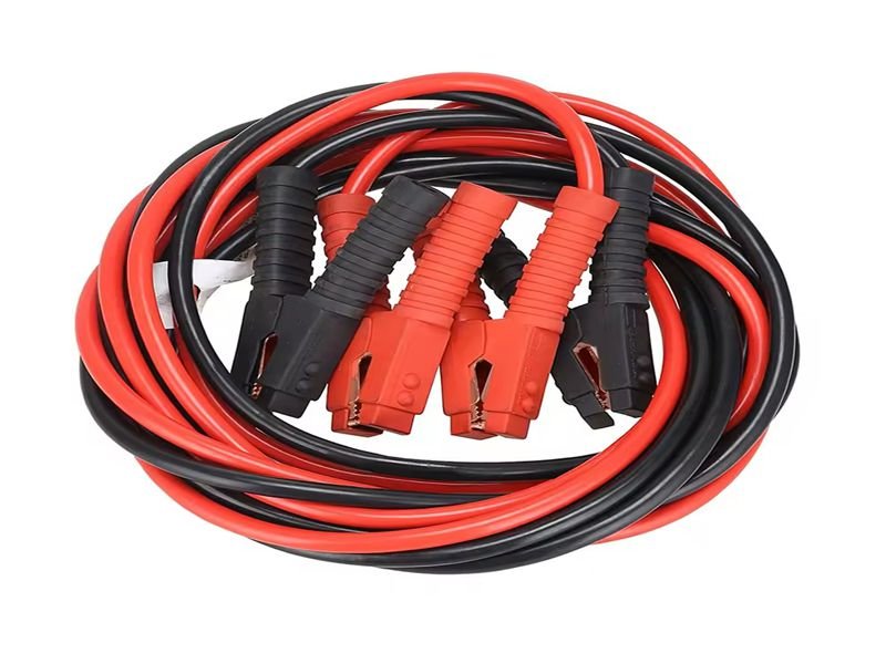
When your car refuses to start, few moments are more stressful — especially in the middle of a workday or during a business trip. Yet behind every successful “jump start” lies one simple but powerful tool: battery cables. Whether you’re an everyday driver or an OEM engineer designing high-current harness systems, understanding how to jump start a car with cables goes far beyond connecting red and black clamps.
To jump start a car with cables, connect the positive (red) clamp to the dead battery’s positive terminal, attach the other red to the good battery’s positive terminal, then connect the black clamp to the good battery’s negative terminal and the final black clamp to an unpainted metal part of the dead vehicle. Start the good car, let it run for a few minutes, and then start the dead one. Disconnect in reverse order.
Knowing this process prevents short circuits, ensures personal safety, and even helps you evaluate cable quality and current-carrying capacity — essential for engineers developing custom battery cable assemblies.
Let’s go step-by-step through not just how to do it, but why it works, what materials matter most, and how Sino-Conn helps global OEMs design safer, more efficient power cables.
What Do You Need to Jump Start a Car?
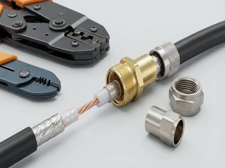
You’ll need a set of heavy-duty jumper cables, a working vehicle with a charged battery, gloves, and eye protection. For consistent performance, use cables made with thick copper conductors, durable insulation, and corrosion-resistant clamps.

A jumper cable isn’t just a “wire” — it’s a temporary power bridge capable of transferring hundreds of amps within seconds. Engineers know that this requires precision in design, from conductor material to insulation resilience.
1. Key Components You’ll Need
| Item | Description | Recommended Specification |
|---|---|---|
| Jumper Cables | Transfers current between vehicles | 4 AWG or thicker |
| Power Source | Working car with charged battery | 12V system |
| Safety Gear | Gloves, goggles | Electrical insulation type |
| Ground Point | Bare metal surface on dead vehicle | Unpainted chassis or engine block |
2. Material & Performance Insights
High-quality jumper cables are typically copper-core, as copper conducts electricity 30–40% more efficiently than aluminum. Aluminum, while cheaper, suffers from higher resistance, leading to voltage drops — a key reason for failed jump starts.
| Material | Conductivity | Weight | Cost | Typical Use |
|---|---|---|---|---|
| Copper | Excellent (100%) | Heavy | Higher | OEM, Industrial |
| Aluminum | Moderate (~61%) | Light | Lower | Budget consumer |
3. Sino-Conn’s Engineering Advantage
Sino-Conn’s custom battery cable assemblies are designed using high-purity copper, flexible silicone or TPE insulation, and UL/ROHS-certified components. Each assembly undergoes voltage-drop testing, bend-cycle analysis, and high-temperature endurance to ensure consistent current flow even under harsh automotive conditions.
How to Properly Connect Jumper Cables Step by Step?
To jump start a car safely, attach the red clamp to the dead battery’s positive terminal, connect the other red clamp to the good battery’s positive terminal, then attach the black clamp to the good battery’s negative terminal and the final black clamp to a clean, unpainted metal surface on the stalled vehicle. Start the donor car first, wait a few minutes, then start the dead car. Disconnect in reverse order.
Jump-starting a car is a simple process when done correctly — but improper connection can cause sparks, damage sensitive electronics, or even result in battery explosion due to hydrogen gas ignition. Following a structured procedure ensures both safety and effectiveness.
1. Prepare Both Vehicles and Safety Gear
Before touching the cables, park both vehicles close enough for the cables to reach, but ensure they do not touch each other.
Turn off both ignitions, remove the keys, and engage parking brakes.
Put on safety gloves and glasses. Car batteries contain sulfuric acid, and small sparks can ignite hydrogen gas released during charging.
Checklist before connection:
- Ignitions off
- Lights and accessories off
- Gear in “Park” or “Neutral”
- Parking brakes on
- Cables untangled and clamps clean
2. Identify Battery Terminals
Locate the positive (+) and negative (–) terminals on both batteries. The positive terminal is typically marked in red and may have a plastic cover. The negative terminal is usually black and connects directly to the vehicle chassis.
If terminals are dirty or corroded, wipe them with a dry cloth to ensure good metal contact. Poor contact can cause voltage drop or arcing.
3. Connect the Jumper Cables in Correct Sequence
This order matters because it controls the electrical circuit and minimizes spark risk:
- Red to Dead (+): Connect the red clamp to the positive terminal of the dead battery. → This establishes the receiving point for current.
- Red to Donor (+): Connect the other red clamp to the positive terminal of the good battery. → Now the positive sides of both batteries are linked.
- Black to Donor (–): Attach the black clamp to the negative terminal of the good battery. → This creates a ground path for the working car.
- Black to Ground (–): Finally, connect the last black clamp to a solid, unpainted metal surface on the dead vehicle (e.g., an engine bolt or frame). → Do not connect directly to the dead battery’s negative terminal, as it can create sparks near hydrogen gas emissions.
This connection sequence ensures that any spark occurs away from the battery, reducing explosion risk.
4. Start the Donor Vehicle and Allow Current Flow
Start the engine of the vehicle with the good battery. Let it idle for about 2–5 minutes. This allows its alternator to push charge into the dead battery.
During this period, lightly revving the donor car (to around 1,500–2,000 rpm) helps increase charging output.
For vehicles with heavily discharged batteries, wait slightly longer — but do not exceed 10 minutes to prevent overheating of cables.
5. Start the Disabled Vehicle
After a few minutes, try to start the car with the dead battery.
If it doesn’t start immediately:
- Wait another 2–3 minutes.
- Check clamp contact points for looseness or corrosion.
- Avoid cranking the engine for more than 10 seconds continuously to prevent starter motor damage.
Once the dead vehicle starts, keep both cars connected and idling for a few minutes to stabilize voltage.

6. Disconnect the Cables in Reverse Order
Disconnecting should always follow the reverse sequence to safely open the circuit:
- Remove the black clamp from the grounded metal surface on the formerly dead car.
- Remove the black clamp from the donor battery (–) terminal.
- Remove the red clamp from the donor battery (+) terminal.
- Finally, remove the red clamp from the revived car (+) terminal.
Ensure the clamps do not touch each other or any metal surface during removal.
After disconnection, let the jumped vehicle run for at least 20–30 minutes to recharge its battery.
7. Technical Notes for Engineers
- A 12V car battery typically outputs 400–600 cold cranking amps (CCA). Jumper cables must safely handle at least this load.
- Correct polarity is critical: reversing connections can destroy alternators and onboard ECUs.
- The voltage between terminals should read about 12.6V (fully charged) and 11.8V (low). After jump-starting, check if the alternator maintains 13.8–14.4V.
- For electric or hybrid vehicles, do not use standard jump-start methods; follow manufacturer-specific isolation procedures.
Summary Table: Safe Jump-Start Sequence
| Step | Connection | Purpose | Common Mistake to Avoid |
|---|---|---|---|
| 1 | Red clamp → Dead (+) | Supply path setup | Touching wrong pole |
| 2 | Red clamp → Donor (+) | Link positives | Loose clamp |
| 3 | Black clamp → Donor (–) | Ground return | Mixing terminals |
| 4 | Black clamp → Ground metal on dead car | Safe grounding | Connecting to dead (–) |
| 5 | Start donor → Start dead car | Power transfer | Rushing the process |
| 6 | Disconnect in reverse order | Safe circuit break | Touching clamps together |
Key Takeaway
Connecting jumper cables correctly is less about memorizing color codes and more about understanding current flow and safety sequencing. Each step — from grounding location to disconnection order — has an engineering reason behind it. Following the process carefully ensures the safety of both vehicles, prevents electronic component damage, and demonstrates the practical value of properly designed, high-quality cable assemblies.
Which Cable Type Is Best for Jump Starting a Car
The best jumper cables are made with thick copper conductors, strong clamps, and double-layer insulation. A 4-gauge or thicker copper cable works well for most passenger cars, while 2-gauge cables are better for trucks, SUVs, and cold-climate starts. Aluminum cables can be lighter and cheaper but are less efficient at carrying current.
Selecting the right jumper cable is not only about convenience — it’s about physics. The cable you choose determines how efficiently current travels between two batteries and how safely that current behaves under high load. The wrong size or material can lead to slow cranking, melted insulation, or permanent battery damage.
1. Understanding Cable Gauge and Current Flow
“Gauge” refers to wire thickness and directly affects current capacity. The smaller the number, the thicker the cable and the higher the current it can safely carry. During a jump start, hundreds of amps flow in a few seconds, so resistance must be minimal.
| Cable Gauge (AWG) | Approx. Max Current (A) | Suitable For | Flexibility | Typical Use |
|---|---|---|---|---|
| 10 AWG | ~50A | Compact cars | High | Light-duty or emergency kits |
| 6 AWG | ~80A | Sedans, small SUVs | Moderate | Standard consumer use |
| 4 AWG | ~150A | Large cars, SUVs | Good | Reliable for most drivers |
| 2 AWG | ~200A–300A | Trucks, diesel engines | Fair | Heavy-duty, professional |
| 1/0 AWG | 300A+ | Buses, construction equipment | Low | Industrial and OEM use |
In practical terms, a 4-gauge cable is ideal for general automotive use. A thicker 2-gauge or 1/0-gauge cable provides better performance in cold conditions, where internal battery resistance rises and engines require higher cranking current.
2. Material Choices: Copper vs. Aluminum
Conductor material determines how well a cable transfers electricity. Two materials dominate the market: copper and aluminum. Each has benefits and limitations.
| Property | Copper | Aluminum |
|---|---|---|
| Conductivity | Excellent (100%) | ~61% of copper |
| Durability | High | Moderate (brittle under bending) |
| Corrosion Resistance | Very good (with tin plating) | Fair; oxidizes easily |
| Weight | Heavier | Lighter (30–40% less) |
| Cost | Higher | Lower |
| Best For | High-current, long-term use | Lightweight, cost-sensitive projects |
Copper is the preferred choice for professional-grade and OEM jumper cables because it minimizes voltage drop and heat generation. Its flexibility and mechanical strength ensure long-term reliability under repeated bending and vibration.
Aluminum cables can still function adequately for occasional personal use, but engineers typically avoid them in applications requiring high durability or low impedance.
3. Clamp Construction and Contact Quality
The clamps are often overlooked but are the true interface between cable and battery. Their design determines how efficiently current transfers without sparking or overheating.
Key factors in a good clamp:
- Material: Solid copper or copper-plated steel improves conductivity.
- Spring tension: Must be strong enough to grip firmly even on corroded posts.
- Jaw surface: Serrated or toothed patterns bite through oxidation and ensure full contact area.
- Insulation: Rubber or PVC coating reduces shock risk and increases grip comfort.
A well-designed clamp reduces contact resistance, often lowering power loss by more than 10% compared to cheap thin-plated models. Engineers typically test clamp resistance (<1 milliohm) as part of quality validation.
4. Insulation, Jacket Material, and Temperature Resistance
Beyond the conductor, insulation quality dictates how a jumper cable behaves in real conditions — from freezing mornings to engine-bay heat.
| Insulation Material | Temp Range (°C) | Flexibility | Oil/UV Resistance | Common Use |
|---|---|---|---|---|
| PVC | –20 to +80 | Moderate | Fair | Consumer-grade |
| TPE | –40 to +125 | High | Good | Mid- to high-end cables |
| Silicone | –60 to +200 | Excellent | Excellent | Professional and OEM cables |
Thicker, flexible insulation prevents cracks in cold weather and melting near hot engine components.
For engineers designing automotive harnesses, silicone or TPE jackets are preferred due to their flexibility and high dielectric strength. They also meet environmental compliance standards such as ROHS and REACH.
5. Cable Length: Finding the Right Balance
While longer cables offer reach and convenience, they also increase resistance. Every additional foot of wire slightly lowers voltage at the receiving battery.
Typical recommendations:
- 12–16 ft (3.5–5 m): Suitable for most vehicles parked nose-to-nose.
- 20–25 ft (6–7.5 m): Useful for roadside assistance or large vehicles.
- >25 ft: Avoid unless using thicker (2 AWG or larger) cables to compensate for voltage drop.
In professional or OEM setups, engineers calculate the total resistance (R = ρL/A) to ensure the system maintains adequate current at the starter motor, typically 9.6 V minimum during cranking.
6. Environmental and Usage Considerations
Different operating environments place unique demands on cable design:
- Cold climates: Choose thicker gauge, flexible silicone insulation, and corrosion-resistant terminals.
- Hot or industrial environments: Use TPE or cross-linked polyethylene jackets to prevent deformation.
- Marine or outdoor applications: Opt for tinned copper conductors and waterproof clamps to prevent oxidation.
7. Summary Table: Selecting the Right Jumper Cable
| Application | Recommended Gauge | Material | Insulation | Ideal Length |
|---|---|---|---|---|
| Passenger car | 4 AWG | Copper | TPE | 12–16 ft |
| Truck / SUV | 2 AWG | Copper | Silicone | 16–20 ft |
| Industrial / OEM use | 1/0 AWG | Tinned Copper | Silicone | Custom |
| Occasional consumer | 6 AWG | Aluminum or Copper | PVC | 10–12 ft |
Choosing jumper cables is a technical decision rooted in current capacity, material conductivity, and environmental durability. Copper remains the industry standard for consistent performance and long life, while insulation quality defines how safely a cable operates under stress. For engineers, these parameters directly inform design choices in any battery cable or power harness system — the goal is always the same: maximize conductivity, minimize loss, and ensure safety under real-world conditions.

Why Do Some Jumper Cables Fail to Work?
Cables fail due to poor contact, undersized wire gauge, or internal corrosion. Inferior insulation or improper crimps also cause voltage drop and weak current transfer.
- Material Deficiency: Many low-cost jumper cables use aluminum-clad steel, which corrodes rapidly and loses conductivity.
- Contact Resistance: Poor-quality clamps with thin plating create high resistance, wasting 10–20% of transmitted power.
- Thermal Stress: Repeated high-amperage surges cause melting or insulation hardening in PVC-coated wires.
- Engineering Control: Sino-Conn employs 3-phase inspection (in-process, final, and pre-shipment), ensuring every battery cable meets or exceeds design specifications.
| Defect | Result | Sino-Conn Control |
|---|---|---|
| Loose crimp | High resistance | Automated crimp testing |
| Thin wire gauge | Overheating | Gauge verification |
| Oxidized clamp | Power loss | Tinned copper terminals |
| Weak insulation | Short circuit | Dielectric breakdown test |
Certifications: All products comply with UL, ISO, ROHS, and REACH standards — vital for OEM qualification.
Are There Safer or Smarter Alternatives to Jumper Cables?
Smart jump starters and lithium boosters offer portable convenience, but heavy-duty jumper cables remain essential for high-current reliability in OEM and industrial use.
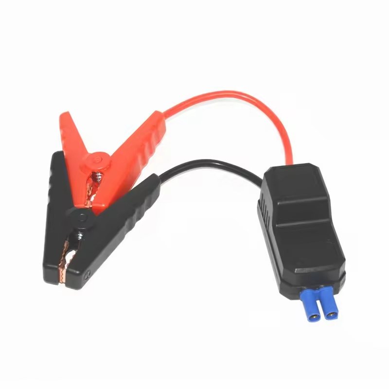
- Smart Jump Starters: Compact, rechargeable, with built-in reverse polarity protection — great for consumers but limited in amperage (<400A).
- Jumper Cables: Handle 800–1000A surges easily; reusable and field-maintainable.
- Hybrid Systems: Combining heavy-gauge cables with smart clamps gives engineers the best of both worlds: reliability and safety automation.
- Sino-Conn OEM Collaboration: Sino-Conn partners with vehicle and battery system developers to integrate custom power harnesses into modern EVs and hybrid jump-start modules, ensuring optimal energy transfer and EMI suppression.
How Can Sino-Conn Help OEMs and Engineers Customize Battery Cable Assemblies?
Sino-Conn designs and manufactures custom battery cable assemblies with flexible material choices, precise pin definitions, and fast 3-day prototyping for automotive and industrial clients.
- End-to-End Engineering: From 30-minute CAD drawings to UL-certified production, Sino-Conn handles full lifecycle design.
- Customization Range:
- Length, conductor type, and terminal orientation
- Overmolding, shielding, and anti-abrasion jacket options
- Voltage/current ratings, fire and oil resistance
- Lead Time: Samples within 3 days, production in 2 weeks.
- MOQ: None — start with 1 piece for validation testing.
- OEM Experience: Trusted by global automotive and industrial clients across the U.S., Germany, Japan, and Southeast Asia.
Why Choose Sino-Conn as Your Battery Cable Manufacturer?
- 100% quality inspection: process + final + shipment.
- Flexible design collaboration with engineers via video or CAD sharing.
- Price advantage through scalable component sourcing.
- Certifications: UL, ISO, ROHS, REACH, PFAS, COC, COO.
- Specialization: Custom battery cables, power harnesses, industrial cables, and overmolded assemblies.

Conclusion:
Jump starting a car with cables is more than a roadside skill — it’s an engineering lesson in current, conductivity, and safety. For OEMs and system designers, these same principles define the difference between an average cable and a high-performance custom battery assembly.
If your next project demands precision, flexibility, and certified reliability, Sino-Conn is ready to collaborate. From rapid 3D drawings to high-current testing, our team ensures every cable performs flawlessly — whether on the road, in the lab, or across your production line.
Contact Sino-Conn today to discuss your custom battery cable, power harness, or industrial cable assembly requirements.