 Skip to content
What Are F Type Connectors for Coaxial Cable and How Do They Work?
- andy
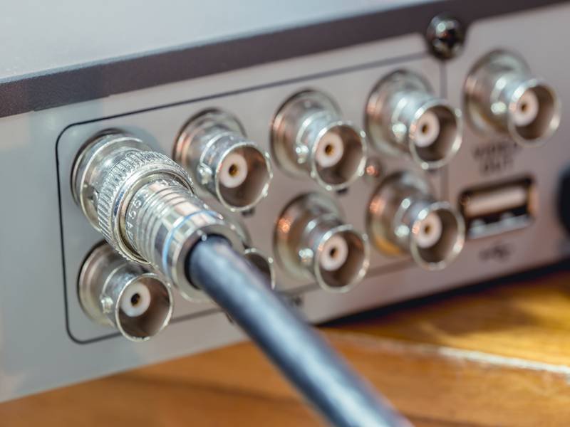
F type connectors are one of the most widely used connectors in coaxial cable systems. They appear simple, inexpensive, and easy to install, which is exactly why they are often underestimated. In many real installations—TV systems, broadband networks, CCTV lines—the connector becomes the weak point, not the cable itself. A small mismatch or poor installation can lead to signal drop, noise, or unstable connection over time.
F type connectors for coaxial cable work by using the cable’s center conductor as the signal contact, while the connector body secures the shielding to maintain grounding and signal continuity. When correctly matched and properly installed, they provide a stable and cost-effective solution for RF and video signal transmission.
The difference becomes clear after installation. Two connectors that look identical can behave very differently. One remains stable for years, while the other causes intermittent issues within weeks. The reason is usually hidden inside—cable fit, stripping accuracy, material tolerance, and assembly quality.
Many customers reach out after facing problems like this: everything works during testing, but once deployed, signal quality drops. In quite a few cases we’ve reviewed, the issue was not the device or the cable length, but the connector termination itself. Understanding how F type connectors actually work—and how they should be selected—can prevent these issues early.
What Are F Type Connectors?
F type connectors are coaxial cable connectors designed to carry RF and video signals through a simple but effective structure. Instead of using a separate center pin, the connector uses the cable’s own center conductor as the signal contact, while the outer metal body grips the shielding layer to maintain grounding and mechanical stability.

This design reduces cost and simplifies assembly, which is why F type connectors are widely used in TV systems, broadband connections, satellite installations, and many video transmission setups. However, this simplicity also means performance depends heavily on how well the connector matches the cable and how accurately it is installed.
What are F type connectors used for?
F type connectors are used in systems where coaxial cable carries RF or video signals over short to medium distances. They are not typically used in high-precision RF laboratory setups, but they are extremely common in large-scale installations where cost, availability, and ease of use matter.
| Application | Why F Type Connectors Are Used | What Usually Matters |
|---|---|---|
| Cable TV distribution | Low cost, stable signal | Consistent connection across many points |
| Broadband internet | Standard interface | Reliable fit and shielding |
| Satellite systems | Works with RG6 / RG11 | Signal stability over distance |
| CCTV video systems | Practical for video signal | Easy installation and maintenance |
| Antenna connections | Simple extension | Mechanical retention |

From actual customer discussions, the same connector is viewed very differently depending on the role:
- Engineers focus on impedance continuity and shielding effectiveness
- Procurement teams focus on price, lead time, and supply consistency
- OEM factories care about assembly speed and failure rate
- Traders often just want to match an existing product
One pattern shows up quite often: a customer sends a photo and asks for “the same connector.” The connector type can usually be identified quickly, but the cable underneath is often unknown. That is where many problems start.
A connector that looks correct can still cause issues if:
- The cable OD is slightly different
- The dielectric size does not match
- The shield structure is not compatible
This is why confirming the cable structure before finalizing the connector choice avoids a lot of trial-and-error later. Many customers prefer to double-check this step, especially when switching suppliers or starting a new project.
What coaxial cable uses F type connectors?
F type connectors are mainly used with RG59, RG6, and RG11 coaxial cables, but the actual fit depends on detailed cable dimensions rather than just the cable name.
| Cable Type | Typical OD Range | Application | Key Consideration |
|---|---|---|---|
| RG59 | ~6.0 mm | CCTV, short runs | Flexible but higher signal loss |
| RG6 | ~6.8–7.2 mm | TV, broadband | Most common, balanced performance |
| RG11 | ~10 mm | Long-distance runs | Lower loss, harder to install |
A common misunderstanding is assuming all RG6 cables are identical. In practice, cables from different suppliers may vary in:
- Outer jacket thickness
- Dielectric diameter
- Shield density (single braid vs foil + braid)
- Conductor material (solid copper vs CCS)
These differences directly affect connector fit.
| Mismatch Type | What Happens | Result in Use |
|---|---|---|
| Connector too loose | Cable not secured | Signal instability, rotation |
| Connector too tight | Cable forced in | Internal damage, poor contact |
| Dielectric mismatch | Uneven support | Signal reflection |
| Shield mismatch | Weak grounding | Increased noise |
When reviewing customer samples, these issues are easy to identify once the cable is opened and measured. That is why many projects benefit from confirming cable OD and structure before selecting connectors.
When working on larger or repeated orders, customers often send a sample or specification first so the connector match can be verified before production. This reduces the risk of field issues later.
Why are F type connectors so common?
F type connectors remain popular because they offer a practical balance between cost, ease of use, and acceptable performance for many applications.
| Advantage | Practical Impact |
|---|---|
| No separate center pin | Lower manufacturing cost |
| Simple structure | Faster assembly |
| Threaded interface | Secure connection |
| Wide compatibility | Works with common cables |
| Easy replacement | Readily available worldwide |
However, the same features that make them easy to use also make them easy to misuse.
Because they look simple, installation details are often overlooked:
- Incorrect strip length
- Uneven shield folding
- Bent center conductor
- Poor compression
These do not always cause immediate failure. Instead, problems show up later as:
- Signal drop after installation
- Intermittent connection
- Noise in the system
- Reduced lifetime
Another factor is connector quality variation.
Not all F connectors are manufactured to the same tolerance. Differences in:
- Material hardness
- Internal dimensions
- Thread precision
can affect:
- Installation consistency
- Retention strength
- Signal stability
This is why some projects that look identical on paper behave differently in real use. The connector is the same type, but the actual fit and assembly result are different.
In practice, a stable coaxial connection comes from three things working together:
- Correct cable selection
- Proper connector match
- Consistent assembly process
When these are aligned, F type connectors perform reliably for most standard applications. When one of them is off, problems tend to appear later during installation or operation.
How Do F Type Connectors Work?
F type connectors work by turning the coaxial cable itself into part of the electrical interface. The center conductor of the cable becomes the signal contact, while the connector body grips the shield and outer jacket to maintain grounding and mechanical stability. When everything is aligned—cable size, stripping dimensions, and connector fit—the signal path remains stable and predictable.
The challenge is that this design leaves very little margin for error. Small variations in cable preparation or connector fit can directly affect performance, which is why two assemblies that look identical may behave differently after installation.
How do F type connectors connect coaxial cable?
The connection is created by preparing the cable and securing it inside the connector so that both the signal path and shielding path are properly maintained.
Typical assembly steps:
- Strip the outer jacket to a controlled length
- Fold the braid or shielding back evenly
- Expose the dielectric and center conductor
- Insert the cable fully into the connector
- Secure using compression or crimp
Each step influences both electrical and mechanical performance.
| Step | What Should Happen | What Goes Wrong |
|---|---|---|
| Jacket stripping | Clean, consistent length | Too long or too short → poor support |
| Shield folding | Even coverage around connector body | Uneven → weak grounding |
| Dielectric exposure | Center conductor aligned | Damaged → impedance issue |
| Cable insertion | Fully seated inside connector | Partial insertion → loose fit |
| Compression/crimp | Firm, uniform hold | Over/under force → instability |
In production environments, even small variations can accumulate.
For example:
- ±0.5 mm variation in stripping length can affect retention
- Uneven compression force can cause connectors to loosen over time
- Inconsistent shield handling can increase noise in certain conditions
This is why many OEM customers prefer controlled assembly instead of manual installation in the field. Once the process is standardized, performance becomes much more consistent across batches.
In projects we’ve reviewed, simply stabilizing the stripping dimensions and compression process reduced failure rates significantly without changing the connector type.
How do F type connectors carry signal?
The signal travels through the center conductor of the coaxial cable, which directly acts as the contact point inside the connector. The outer shield provides the return path and helps maintain electromagnetic stability.
Because the connector does not use a separate internal pin, the signal path is shorter and simpler—but also more sensitive to alignment and contact quality.
Key factors affecting signal transmission:
| Factor | Good Condition | Poor Condition |
|---|---|---|
| Center conductor alignment | Straight and centered | Bent or off-center |
| Contact stability | Firm and consistent | Loose or intermittent |
| Shield connection | Continuous and even | Partial or weak |
| Dielectric integrity | Maintains structure | Crushed or uneven |
When these conditions are met:
- Signal loss remains low
- Connection stays stable over time
- Performance is repeatable across installations
When they are not:
- Signal attenuation increases
- Reflection may occur
- Noise becomes more noticeable
In real troubleshooting cases, signal issues are often traced back to connector termination rather than cable defects.
A typical scenario:
- Cable tests well before installation
- After installation, signal becomes unstable
- Replacing connector or re-terminating resolves the issue
This happens because the connector interface is where mechanical and electrical factors meet. Any small imperfection here directly affects the signal path.
Why does F type connector installation matter?
Installation determines whether the connector performs as expected under real conditions.
Even a well-designed connector can fail if installation is inconsistent.
Key factors that affect long-term performance:
| Factor | Impact |
|---|---|
| Stripping accuracy | Controls conductor and dielectric position |
| Shield preparation | Ensures proper grounding |
| Compression consistency | Maintains retention strength |
| Cable alignment | Prevents signal distortion |
| Environmental sealing | Protects against moisture |
Common issues seen after installation:
| Problem | Likely Cause |
|---|---|
| Signal drop after setup | Poor conductor contact |
| Intermittent connection | Loose connector |
| Noise in system | Weak shielding connection |
| Failure over time | Environmental exposure |
These problems often do not appear immediately. They show up after:
- Temperature changes
- Mechanical vibration
- Repeated use
- Outdoor exposure
For example:
- Outdoor installations without proper sealing → moisture enters connector
- Industrial environments → vibration loosens poorly secured connectors
- Long cable runs → amplify small signal losses
To reduce these risks, many projects move toward pre-assembled cable solutions where the connector is installed under controlled conditions.
This approach improves:
- Consistency
- Installation speed
- Reliability
For customers working with larger volumes or strict quality requirements, this shift usually reduces rework and field issues.
In practice, reviewing the cable structure and connector match before production helps avoid most of the common problems seen later. It also shortens the troubleshooting cycle when something does go wrong.
Which F Type Connectors Should You Choose?
Choosing an F type connector is less about the connector name and more about how well it matches your cable, your installation method, and your long-term use conditions. In many projects, the connector type is selected first and the cable is treated as secondary. In practice, it should be the other way around—connector choice should follow the actual cable structure and application.
A connector that fits correctly and is installed consistently will usually perform well. A connector that is slightly mismatched may still “work,” but tends to cause issues later—loose fit, signal drop, or variation between batches.
Which F type connectors fit RG6 and RG59?
F connectors are commonly labeled for RG6 or RG59, but real fit depends on actual cable dimensions rather than the label alone. Different cable suppliers use different materials and tolerances, which changes outer diameter and dielectric size.
| Cable Type | Typical OD Range | Recommended Connector | What to Check First |
|---|---|---|---|
| RG59 | ~5.8–6.2 mm | RG59-specific connector | OD and dielectric size |
| RG6 | ~6.8–7.2 mm | RG6 compression connector | Jacket thickness and shield |
| RG11 | ~9.5–10.5 mm | RG11 connector | Insertion depth and tool compatibility |
What usually causes problems:
- Connector designed for 7.2 mm cable used on 6.6 mm cable → loose hold
- Connector forced onto larger OD cable → dielectric deformation
- Different braid/foil structure → inconsistent grounding
These differences are small on paper but visible in installation:
- Connector rotates after tightening
- Cable can be pulled out with low force
- Signal performance varies across batches
A quick check that many teams use before bulk purchase:
- Measure cable OD with caliper
- Check dielectric diameter after stripping
- Test connector insertion force (should be firm but not forced)
When customers send mixed samples (different suppliers, same cable name), these variations become obvious. Matching connectors based on real measurements rather than catalog names usually prevents most fit-related issues.
Which F type connectors are better: compression or crimp?
The two main options in professional use are compression and crimp connectors. Twist-on connectors exist, but they are mainly used for temporary or low-cost installations.
| Type | Pull Strength (Typical) | Consistency | Tool Requirement | Typical Use |
|---|---|---|---|---|
| Compression | 60–100 N | High | Compression tool | Professional/OEM |
| Crimp | 40–80 N | Medium (process-dependent) | Crimp tool | Production lines |
| Twist-on | 20–40 N | Low | No special tool | Temporary/DIY |
How they behave in real use:
- Compression connectors: tighter seal, better for outdoor or long-term use; more consistent when the tool is controlled
- Crimp connectors: stable when process is standardized; sensitive to tool calibration
- Twist-on connectors: fast and cheap; tend to loosen over time, especially with vibration
Where problems usually appear:
- Compression connectors with inconsistent tool stroke → uneven retention
- Crimp connectors with wrong die size → loose or over-compressed
- Twist-on connectors in outdoor use → moisture ingress and loosening
For OEM production, consistency matters more than connector type alone. Many factories choose compression connectors when they need repeatable results across thousands of pieces. Others use crimp connectors but standardize tooling and inspection.
In projects where installation time and rejection rate are critical, moving to pre-terminated assemblies often improves overall results. This is especially useful when different installers are involved or when installation conditions vary.
How to choose F type connectors for your use?
Connector selection should follow the actual use scenario. The same connector may perform well in one setup and fail in another.
A practical way to decide is to start from the application, not the connector.
| Scenario | Recommended Setup | Reason |
|---|---|---|
| Indoor fixed installation | Standard compression connector | Stable and easy to install |
| Outdoor installation | Weather-sealed compression | Prevents moisture ingress |
| High vibration area | High-retention compression | Reduces loosening |
| Tight installation space | Smaller OD cable + matched connector | Easier routing |
| Cost-sensitive project | Balanced connector + cable choice | Control total cost |
Key questions to ask before selecting:
- Is the cable fixed or subject to movement?
- Will the installation be indoors or outdoors?
- Is long-term stability required, or is it temporary?
- Who will install it—trained staff or field technicians?
- How important is consistency across large quantities?
Typical issues when these are ignored:
| Situation | Result |
|---|---|
| Indoor connector used outdoors | Corrosion and signal loss |
| Standard connector in vibration area | Loosening over time |
| Low-cost connector in long-term system | Maintenance and rework |
| Mismatched connector for cable OD | Fit and signal issues |
For projects with larger volumes or tighter requirements, many teams prefer to define the connector and cable combination early and keep it consistent across production. This reduces variation and simplifies both installation and quality control.
When customers share more than just the connector name—such as cable sample, OD, environment, and expected usage—it becomes much easier to recommend a setup that works without repeated adjustments.
Why Do F Type Connectors Fail?
F type connectors usually fail for practical reasons, not mysterious ones. Most failures come from mismatch, poor installation, weak process control, or using the connector in conditions it was not selected for. The connector may still pass a quick bench test, but problems often appear later—after routing, tightening, vibration, weather exposure, or repeated use.
For customers, this is where cost and quality start to separate. A connector that looks fine in a product photo may still cause signal drop, loose fit, return issues, or rework during installation. In many cable assembly projects, the connector is not the most expensive part, but it can easily become the part that creates the most complaints.
Why do F type connectors cause signal loss?
Signal loss usually starts when the electrical path inside the connector is no longer stable. In an F type connector, the cable center conductor acts as the signal contact. That means any error in conductor length, straightness, insertion depth, dielectric support, or shield contact can affect performance directly.
The most common signal-loss causes are listed below:
| Cause | What Happens Inside the Connector | Result in Use |
|---|---|---|
| Center conductor too short | Weak contact with mating port | Unstable or low signal |
| Center conductor bent | Incomplete or off-center contact | Intermittent transmission |
| Dielectric damaged during stripping | Impedance disturbance | Reflection, weaker signal |
| Shield not seated correctly | Poor return path | Noise and signal instability |
| Connector not fully seated | Internal looseness | Variation between pieces |
In actual installations, customers usually notice signal loss in these ways:
- TV or video image becomes unstable
- Internet signal weakens or drops unexpectedly
- Signal quality changes after the cable is moved
- One batch works better than another even with the same drawing
The difficult part is that connector-related loss often looks like a device problem at first. Many teams change cables, splitters, or equipment before checking the connector termination itself.
A simple example: if the center conductor is 0.5 mm shorter than needed, the connector may still thread in and appear normal from outside. But the contact pressure inside may be weak, which can cause inconsistent signal under vibration or temperature change. On short cable runs this may go unnoticed. On longer runs or weaker systems, it becomes obvious quickly.
This is why the connector should not be judged only by “can it be installed.” It should be judged by whether it keeps signal stable after installation.
What mistakes happen with F type connectors?
Most F type connector failures are caused by small process errors that repeat over and over. One connector may still work. One hundred pieces from the same process may show a clear pattern of failure.
Here are the mistakes that show up most often:
| Common Mistake | Immediate Effect | Later Problem |
|---|---|---|
| Wrong connector for cable OD | Poor fit | Rotation, pull-out, unstable signal |
| Strip length too long | Weak support inside connector | Wobble, poor retention |
| Strip length too short | Incomplete insertion | Weak grounding, poor contact |
| Braid folded back unevenly | Inconsistent shield contact | Noise and return path issues |
| Over-compression or wrong crimp die | Cable deformation | Damaged dielectric, signal variation |
| Under-compression | Loose hold | Connector loosens in use |
| Using indoor connector outdoors | No proper sealing | Moisture entry, corrosion |
In field work, these mistakes often come from speed. Installers want to finish quickly. In production, they often come from variation. One operator strips slightly differently from another. One tool applies a different force from another. A connector that is tolerant enough for hand assembly may still be too inconsistent for OEM production.
This is why some customers experience a frustrating pattern:
- Sample works
- Small batch works
- Larger batch starts showing random failures
The reason is usually not random at all. It is process variation finally becoming visible at scale.
When reviewing customer problems, one repeated theme is that the connector type itself is often acceptable, but the preparation method is not controlled tightly enough. Once the stripping length, insertion depth, and compression force are stabilized, the rejection rate drops sharply.
That is one reason many OEM customers move away from loose field assembly and toward pre-terminated cable sets. It reduces operator variation and makes inspection easier before shipment.
How to avoid F type connector problems?
Avoiding F type connector problems starts much earlier than final installation. It begins with the right connector-cable match, then continues through cable preparation, tooling, inspection, and environmental fit. Most failures can be prevented before the finished assembly ever reaches the customer site.
A practical prevention checklist looks like this:
| Control Point | What to Check | Why It Matters |
|---|---|---|
| Cable OD | Measure with caliper | Prevent loose or forced fit |
| Dielectric size | Check after stripping | Supports correct internal contact |
| Connector type | Match to cable and application | Avoid mismatch and weak retention |
| Tool setting | Verify compression or crimp condition | Improve consistency |
| Strip dimensions | Standardize and inspect | Maintain conductor and shield position |
| Outdoor sealing | Confirm weather resistance | Reduce corrosion risk |
| Finished pull test | Verify retention | Catch weak assembly early |
For customers managing larger volumes, it helps to separate problems into three categories:
1. Design mismatch
The connector was never a good fit for the cable or environment.
2. Process variation
The design is acceptable, but stripping, insertion, or compression is inconsistent.
3. Use-condition overload
The connector is acceptable for indoor fixed use, but the actual application includes vibration, outdoor exposure, or repeated handling.
Each category needs a different solution.
A useful decision table is below:
| Problem Source | Best Fix |
|---|---|
| Wrong connector-to-cable match | Reconfirm cable dimensions and connector model |
| Poor installation consistency | Standardize tools, dimensions, and inspection |
| Outdoor failure | Upgrade sealing and corrosion resistance |
| Frequent loosening | Improve retention style or move to pre-assembled cable |
| Batch-to-batch variation | Lock supplier, tooling, and process parameters |
For projects with repeat orders, many customers now prefer to confirm the structure once and keep it locked. That includes cable type, connector model, strip dimension, tool type, and inspection standard. This reduces surprises later.
At Sino-Conn, this is usually where support adds the most value. Customers may start with only a sample, a cable photo, or a rough part description. From there, the cable OD, shielding structure, connector fit, and assembly method can be checked before production. Drawings can be prepared quickly, and the confirmed structure is then used as the reference for sampling and mass production. That approach is especially useful when customers want to reduce rejection, shorten troubleshooting time, and keep repeat orders consistent.
In practical terms, F type connector problems are usually avoidable. The connector itself is simple. The real difference comes from how carefully the details are handled before the cable ever reaches the installation site.
How to Customize F Type Connectors?
Customizing F type connector cable assemblies is about getting the connector, cable, and use condition to work together from the start. Most issues seen later—loose fit, signal drop, moisture ingress, or inconsistent batches—come from treating the connector as a generic part. In practice, small changes in cable structure or connector fit can shift performance noticeably.
A well-defined assembly usually reduces installation time, lowers rejection rate, and keeps performance consistent across batches. For projects that move from samples to volume, this step becomes more important than choosing the “cheapest” connector.
What can be customized in F type connector cables?
Even though F connectors look standardized, several parameters can be adjusted to match your application. The key is to focus on the items that affect fit, signal stability, and installation efficiency.
| Custom Item | Options | What It Changes |
|---|---|---|
| Cable type | RG59 / RG6 / RG11 | Attenuation, flexibility, routing |
| Cable OD | Within supplier tolerance | Connector fit and retention |
| Connector type | Compression / crimp | Installation consistency and pull strength |
| Connector material | Standard / corrosion-resistant | Outdoor lifetime |
| Shield structure | Braid / foil + braid / higher coverage | Noise and return path stability |
| Jacket | PVC / PE / UV-resistant | Indoor vs outdoor durability |
| Length | Custom (mm–meters) | Installation layout |
| End style | Straight / right-angle / adapter | Space constraints |
| Assembly method | Standard / reinforced | Vibration and handling resistance |
Typical requests from customers include:
- “Keep the same connector, but adjust cable length for cabinet layout”
- “Improve outdoor durability without changing the system interface”
- “Reduce cost for higher quantities while keeping stable performance”
- “Tighten the fit—current connector rotates after installation”
Each request affects more than one parameter. For example, improving shielding can increase stiffness, which may affect routing. Reducing OD can help installation in tight spaces, but may require a different connector size to maintain retention.
In many projects, customization starts from limited information—a photo, a sample, or a part number. From there, the full structure is defined step by step: measure the cable, confirm the connector fit, set strip dimensions, and lock the assembly method before sampling.
How to balance cost and performance for F type connectors?
Cost is not just the connector price. It includes installation time, failure rate, rework, and maintenance. A lower unit price can increase total cost if the connector is inconsistent or requires more time to install.
A practical way to compare options is:
| Option | Performance | Cost | Typical Outcome |
|---|---|---|---|
| Compression connector + stable cable | High | Medium–High | Consistent installation, low rework |
| Crimp connector + controlled process | Medium–High | Medium | Good balance if tooling is stable |
| Low-cost connector without process control | Low–Variable | Low | Higher variation, possible field issues |
Connector sourcing also affects both cost and lead time:
| Connector Source | Advantage | Trade-off |
|---|---|---|
| Original brand | Consistent tolerance | Higher cost, longer lead time |
| Equivalent supplier | Flexible supply, lower cost | Requires validation for fit |
In many projects, teams use a phased approach:
- Sample stage: focus on quick validation and fit (often more flexible sourcing)
- Pre-production: confirm dimensions, strip specs, and tool settings
- Mass production: lock materials and process to keep consistency
Where costs often increase unexpectedly:
- High rejection rate due to loose fit
- Extra labor from re-terminating connectors
- Field returns caused by moisture or loosening
- Longer installation time per piece
For OEM lines, even a 10–15% reduction in rework can offset a slightly higher connector cost. That is why many teams optimize for stability first, then adjust cost once the structure is proven.
How fast can F type connector cables be made?
Lead time depends on how clearly the structure is defined. When the cable type, connector match, and assembly method are confirmed early, sampling and production move faster and with fewer revisions.
Typical timeline:
| Stage | Standard Time | Fast Option |
|---|---|---|
| Drawing / confirmation | 1–3 days | Same day when details are clear |
| Sample | ~2 weeks | 2–3 days for urgent cases |
| Mass production | 3–4 weeks | ~2 weeks for simplified builds |
Different customers focus on different parts of this timeline:
- Engineering teams want quick samples to validate fit and signal
- OEM factories need stable schedules and repeatable output
- Procurement looks for predictable delivery and minimal changes
Speed is not only about manufacturing. It is also about how quickly the structure is clarified:
- Confirming cable OD and dielectric size early avoids rework
- Locking strip dimensions reduces trial runs
- Selecting the correct connector type prevents late changes
In projects where time is tight, fast drawing confirmation and early sample checks usually save more time than trying to accelerate production later.
What information should you provide to start customization?
You do not need a full specification to start. Most projects begin with partial information and are refined step by step.
Useful inputs include:
| Information | Why It Helps |
|---|---|
| Cable sample or photo | Identifies structure and connector style |
| Cable type or OD | Determines connector fit |
| Application (TV, broadband, outdoor) | Guides material and sealing |
| Installation method | Affects connector choice (compression/crimp) |
| Environment | Decides jacket and corrosion resistance |
| Quantity | Influences cost approach and tooling |
A typical workflow looks like this:
- Review sample or description
- Measure cable OD and dielectric
- Select connector type and confirm fit
- Define strip dimensions and tooling
- Create drawing for confirmation
- Build samples and verify
- Lock parameters for production
This approach reduces back-and-forth and avoids late-stage changes.
For projects that require stable quality across batches, many customers prefer to fix the structure once and keep it consistent. That includes connector model, cable supplier, strip dimensions, and tooling settings. It simplifies incoming inspection and reduces variation in installation.
When working with Sino-Conn, customers often start with a sample or a basic requirement and then refine the assembly together. Drawings can be prepared quickly for confirmation, and the same structure is maintained through sampling and mass production. This helps keep fit, signal behavior, and installation results consistent, especially for repeat orders.
A customized F type connector cable is not about adding complexity. It is about removing uncertainty—so the cable fits correctly, installs cleanly, and performs the same way every time.
Ready to Customize Your F Type Connector Cable?
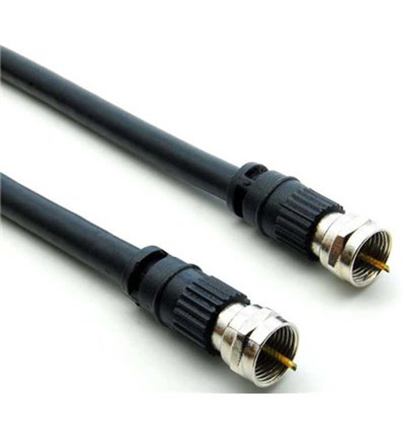
By now, it’s clear that F type connectors are simple in design but sensitive in execution. Most issues—signal loss, loose fit, inconsistent performance—do not come from the connector concept itself, but from how it is selected, matched, and assembled.
What customers usually experience
In many projects, the process looks like this:
- Start with a standard connector
- Encounter signal or fit issues
- Try different suppliers or parts
- Spend time troubleshooting
The root cause is often:
- Connector not matched to cable
- Installation variation
- Lack of structure definition before production
What makes the difference
When the connector, cable, and assembly process are defined clearly at the beginning:
- Signal becomes stable
- Installation becomes easier
- Production becomes consistent
- Field issues are reduced
This is why many customers move from “buying connectors” to “defining cable assemblies.”
How projects usually move forward
You don’t need complete technical data to start.
Most projects begin with:
- A sample
- A photo
- A part number
- Or a simple application description
From there, the structure can be defined step by step:
- Confirm cable type
- Match connector
- Define assembly method
- Optimize cost and lead time
Let’s move your project forward
If you are working on coaxial cable assemblies with F type connectors, getting the details right early can save time, reduce cost, and avoid repeated adjustments later.
Sino-Conn supports:
- Custom cable assembly design
- Fast drawing (as quick as 30 minutes)
- Flexible production (no MOQ)
- Multiple cost options (original or equivalent connectors)
- Stable quality with full inspection
Whether you are:
- Developing a new project
- Improving an existing design
- Looking for a more reliable supplier
You can start by sharing what you have—sample, drawing, or idea—and build from there.
If you have an F type connector cable requirement, you can reach out to Sino-Conn to discuss your project.
Related Keywords :f type connectors, f type connector cable, coaxial cable connector, f connector rg6, f connector rg59, rg6 connector, rg59 connector, coaxial cable assembly, compression f connector, crimp f connector, twist on f connector, coaxial cable signal loss, tv coax connector, satellite coax connector, broadband coax cable, custom coaxial cable, cable connector manufacturer, rf cable assembly, coaxial connector supplier, Sino-Conn

With over 18 years of OEM/ODM cable assemblies industry experience, I would be happy to share with you the valuable knowledge related to cable assemblies products from the perspective of a leading supplier in China.
manufacturer catalogue
Get A Sample Now From Factory→
Get a quote quickly
Here, developing your OEM/ODM custom cable assemblies collection is no longer a challenge—it’s an excellent opportunity to bring your creative vision to life.



