 Skip to content
 How to Coaxial Cable Connector: Types, Installation, and Best Practices
- andy

Installing a coaxial cable connector seems simple—until the signal drops, the connector pulls loose, or the cable suffers from interference and poor shielding. Whether in telecom, surveillance systems, RF communication, test equipment, satellite TV, or broadband networks, reliable coaxial terminations are essential for preserving signal integrity. A poorly installed connector can cause impedance mismatch, loss, noise, or intermittent connection—issues that technicians, engineers, and OEM buyers encounter every day.
A coaxial cable connector attaches to a coax cable by preserving the shielding layers and connecting the center conductor to the correct interface. The installation method depends on the connector type—twist-on, crimp, compression, or solder—and the coax model (RG6, RG59, RG174, RG316, LMR-series, etc.). A correct installation requires proper cable stripping, shielding preparation, ferrule placement, and connector termination to ensure low-loss, interference-free performance.
Many Sino-Conn customers send photos of damaged coax cables or ask whether we can build cables with “the same connector but better shielding.” Others want to know why their connector overheats or why their RF performance drops. The truth is, connector structure, cable construction, and installation method all affect the final RF characteristics.
Now let’s go deeper into coax connector types, tools, installation steps, and how to choose the right connector for your application.
What Are the Main Types of Coaxial Cable Connectors?
Coaxial cable connectors are specialized interfaces designed to maintain the cable’s impedance, shielding, and RF performance while enabling secure electrical connection between devices. The most widely used connector families include F-Type, BNC, SMA, N-Type, UHF/PL-259, and miniature connectors such as MMCX/MCX. Each connector supports different frequency ranges, cable sizes (RG6, RG59, RG174, RG316, LMR series, etc.), and applications—from broadband and CCTV to RF communications and test equipment.
The “best” coaxial connector depends on three core variables:
(1) frequency,
(2) impedance (50 Ω or 75 Ω), and
(3) cable type.
Understanding their differences helps engineering teams, installers, and procurement specialists select connectors that deliver low-loss, interference-free performance.

1. F-Type Connector (TV, Broadband, Satellite)
F-type connectors are widely used in home and commercial video systems. They are simple, cost-effective, and designed for 75-ohm RG6/RG59 cables.
Common applications:
- Cable TV
- Satellite receivers
- Broadband modems
- DVR and set-top boxes
Characteristics:
- Typically compression-style installation
- Low-frequency use (up to ~3 GHz)
- Threaded design for secure fit
Advantages:
- Low cost, easy to install
- Reliable for residential and commercial TV networks
Limitations:
- Not suitable for high-frequency RF beyond a few GHz
- Not weather-sealed unless specified
2. BNC Connector (Video, Test Equipment, RF Under 4–6 GHz)
BNC connectors are used in professional video systems, lab equipment, and moderate-frequency RF applications.
Common applications:
- Analog CCTV & SDI video
- Oscilloscopes and test equipment
- Low-frequency RF systems (50 Ω or 75 Ω versions)
- Broadcast environments
Characteristics:
- Bayonet locking mechanism (quick twist-lock)
- Available in 50-ohm and 75-ohm types
Advantages:
- Fast connect/disconnect
- More secure than simple push-on connectors
Limitations:
- Not designed for very high frequencies (>6 GHz)
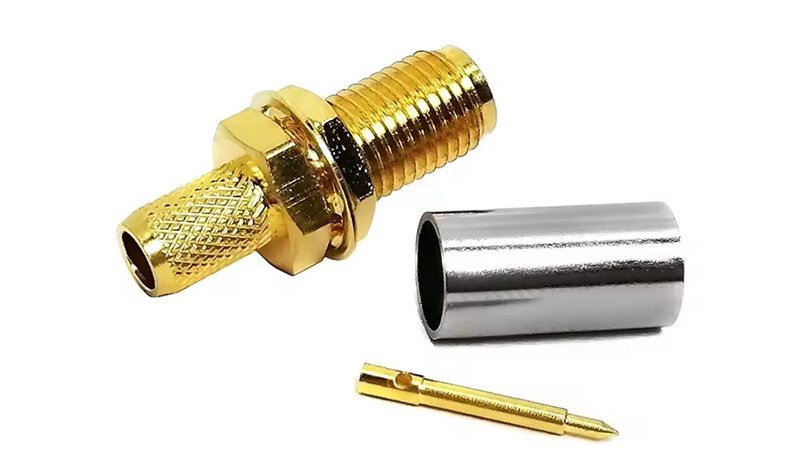
3. SMA and RP-SMA Connectors (High-Frequency RF)
SMA connectors are precision RF connectors supporting high frequencies (up to 18–26 GHz depending on grade). RP-SMA (reverse polarity) is common in wireless products.
Common applications:
- Wi-Fi antennas
- RF modules and IoT devices
- GPS systems
- Test equipment
Characteristics:
- Threaded interface
- Excellent impedance control (50 Ω)
- Used with RG174, RG316, LMR100, and micro-coax
Advantages:
- High frequency support
- Secure, vibration-resistant connection
Limitations:
- Small center pin easy to damage if misaligned
- Requires precise cable prep
4. N-Type Connector (Outdoor, High Power, Telecom)
N-type connectors are robust, weather-resistant, and used for outdoor or high-power RF systems.
Common applications:
- Telecom base stations
- 5G/4G antennas
- Radar systems
- Outdoor RF links
Characteristics:
- Threaded locking design
- Waterproof options (IP67/IP68)
- Works with larger cables like LMR-400, RG213
Advantages:
- Excellent power handling
- Maintains performance up to 11–18 GHz (depending on variant)
Limitations:
- Larger size compared to SMA/BNC
5. UHF / PL-259 (Legacy, Amateur Radio)
UHF connectors (PL-259/SO-239) are used mainly in amateur radio due to their ease of use, but they are not true constant-impedance connectors.
Common applications:
- Ham radio
- CB radio
- HF (high-frequency) communication
Characteristics:
- Not strictly 50 Ω across all frequencies
- Suitable for low-frequency RF (<300 MHz)
Advantages:
- Simple and durable
- Good for high-power low-frequency work
Limitations:
- Not suitable for higher-frequency modern RF systems
6. MMCX / MCX Connectors (Miniature & Micro-Coax)
These connectors appear in compact RF products where space is limited.
Common applications:
- Wearables
- Drones
- IoT sensors
- GPS modules
Characteristics:
- Snap-on mating
- Typically used with micro coax (1.13 mm, 1.37 mm, 1.48 mm)
Advantages:
- Very small footprint
- Quick connect/disconnect
Limitations:
- Not suitable for heavy mechanical stress
- Limited power handling
Comparison Table: Coaxial Connector Types
| Connector Type | Impedance | Typical Frequency Range | Cable Compatibility | Common Applications |
|---|---|---|---|---|
| F-Type | 75 Ω | Up to ~3 GHz | RG6, RG59 | TV, satellite, broadband |
| BNC | 50/75 Ω | 0–6 GHz | RG59, RG58, RG6 | CCTV, test equipment |
| SMA / RP-SMA | 50 Ω | Up to 18–26 GHz | RG174, RG316, LMR100 | Wi-Fi, antennas, RF modules |
| N-Type | 50 Ω | Up to 11–18 GHz | LMR-400, RG213 | Telecom, outdoor RF |
| UHF/PL-259 | Varied | <300 MHz | RG8, RG213 | Amateur radio |
| MMCX/MCX | 50 Ω | Up to 6 GHz | Micro-coax | IoT, compact electronics |
How to Install a Coaxial Cable Connector?
Installing a coax connector requires properly stripping the cable, preparing layers, inserting the center pin, securing the braid, and attaching the connector body. The method varies by connector type (compression, crimp, solder).
To install a coax connector, strip the cable to expose the center conductor and shielding, fold back the braid, insert the dielectric and conductor into the connector body, and secure the connector using compression, crimping, or soldering. Proper alignment and shielding preservation are essential to prevent signal loss and maintain impedance.
1. Tools Required
- Coax cable stripper
- Crimping tool or compression tool
- Soldering iron (for SMA or specialized connectors)
- Utility knife
- Cable cutter
- Heat shrink (optional)
2. Standard Strip Dimensions Table
| Cable Type | Center Conductor Exposure | Dielectric Exposure | Shield/Braid Exposure |
|---|---|---|---|
| RG6 | ~6 mm | ~6 mm | ~12 mm |
| RG59 | ~5 mm | ~5 mm | ~10 mm |
| RG174 / RG316 | ~2 mm | ~3 mm | ~6 mm |
3. General Installation Process
Step 1: Cut the Cable Cleanly
Use a sharp cutter to avoid deforming the dielectric. A crushed dielectric increases return loss and affects RF performance.
Step 2: Strip the Cable
Use a coax stripper set to the correct depth. Avoid nicking the center conductor, which weakens mechanical stability and affects long-term reliability.
Step 3: Prepare the Shielding
Fold back the braid evenly around the jacket. Ensure there are no stray braid strands touching the center conductor (risk of short circuit).
Step 4: Insert the Cable into the Connector
Push firmly so the dielectric seats fully into the connector body. For SMA/N-type, ensure the pin is fully engaged.
Step 5: Crimp, Compress, or Solder
- Compression (F-type): Fast, consistent
- Crimp (BNC, SMA): Reliable when using correct ferrule
- Solder (some SMA): Highest precision
Step 6: Inspect the Joint
Look for:
- No exposed stray braid
- Connector firmly aligned
- Pin depth matching spec
- No wobble or rotation
Improper installation increases VSWR and signal loss—critical in high-frequency applications.
How Do Crimp, Compression, and Solder Connectors Differ?
The termination method affects mechanical strength, signal reliability, and long-term durability.
Crimp connectors use a ferrule and crimp tool for fast, secure terminations. Compression connectors provide strong mechanical retention and are common for TV/RG6 cables. Solder connectors offer the highest electrical performance and are preferred in precision RF applications. The best method depends on connector type, required reliability, and installation environment.
Comparison Table: Termination Methods
| Method | Advantages | Limitations | Typical Connectors |
|---|---|---|---|
| Crimp | Fast, repeatable, strong | Requires exact ferrule size | BNC, SMA, N-type |
| Compression | Very strong, weatherproof | Needs specific tool | F-type, RG6 connectors |
| Solder | Best electrical performance | Slower, requires skill | SMA, U.FL adapters |
How to Choose the Right Coaxial Cable Connector?
Connector selection depends on frequency range, cable type, installation environment, and mechanical requirements.
Choose a connector that matches your cable’s impedance, frequency range, and physical size. High-frequency RF systems require precision connectors like SMA or N-type. Consumer TV systems use F-type. Outdoor and telecom applications require weatherproof connectors. Matching connector type to cable model (RG6, RG59, RG174, LMR series) prevents signal loss and mechanical failure.
Key Factors to Evaluate
1. Cable Type (RG or LMR Model)
Connectors must match:
- Outer diameter
- Dielectric diameter
- Shield structure
- Impedance (50Ω or 75Ω)
2. Frequency Range
- 0–3 GHz: F-type, BNC
- 3–18 GHz: SMA, N-type
- 18–26 GHz: Precision SMA
- >26 GHz: 2.92 mm, 2.4 mm, etc.
3. Environment
- Indoor: Standard connectors
- Outdoor: N-type waterproof, weather-sealed designs
- Vibration: Crimp + strain relief
4. Power Levels
High-power RF systems require connectors with larger contact points and better heat dissipation (N-type, UHF/PL-259).
Common Issues and How to Avoid Them
1. High VSWR / Signal Loss
Caused by:
- Improper stripping
- Poor shielding contact
- Misaligned center pin
2. Overheating
Usually from:
- High-power RF and poor crimp
- Loose braid contact
3. Connector Pull-Out
Solution:
- Use correct ferrule size
- Apply proper crimp force
- Add strain relief
How Sino-Conn Supports Custom Coaxial Cable Assemblies
Sino-Conn provides end-to-end support for coaxial cable assemblies across RF, telecom, 5G, IoT, medical, and industrial markets.
We Offer:
- BNC, SMA, N-type, MMCX, MCX, QMA, U.FL, IPEX, RP-SMA
- Custom lengths (any gauge, OD, or jacket material)
- Drawings delivered within 30 minutes–3 days
- No MOQ (1 piece acceptable)
- OEM branding and private molding
- UL, ISO, RoHS, REACH, PFAS certifications
- 3-stage full inspection (process + final + pre-shipment)
Connector Options
- Genuine brand connectors (Amphenol, Molex, TE)
- Compatible alternatives at lower cost
- Ability to match customer’s sample or photo exactly
Ready to Build a Custom Coaxial Cable Assembly?
Whether you need SMA, BNC, N-type, F-type, RP-SMA, or miniature coax for IoT devices, Sino-Conn can design and manufacture connectors and cable assemblies tailored to your exact specifications. Send your drawing, sample, model number, or even a simple photo—we will provide a precise quote, full spec sheet, and CAD drawings quickly.

Contact Sino-Conn to customize your coaxial cable connector solution today.
Related Keywords :coaxial cable connector, coax connector installation, coax cable types, RG6 connector, crimp vs compression connector, RF cable assembly, SMA connector, BNC connector, how to install coaxial connector, custom coax cable assemblies

With over 18 years of OEM/ODM cable assemblies industry experience, I would be happy to share with you the valuable knowledge related to cable assemblies products from the perspective of a leading supplier in China.
manufacturer catalogue
Get A Sample Now From Factory→
Get a quote quickly
Here, developing your OEM/ODM custom cable assemblies collection is no longer a challenge—it’s an excellent opportunity to bring your creative vision to life.


