Skip to content
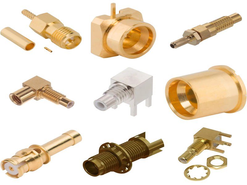
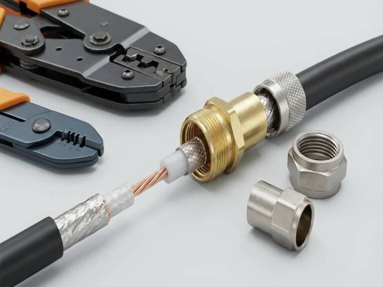
In modern communication systems, accuracy depends on more than just quality cable — it relies on how well signals are terminated. Whether you’re configuring an RF analyzer, CCTV network, or high-frequency test bench, improper termination can mean unstable performance, ghosting, or even total signal loss. A coaxial terminator might look like a simple plug, but it performs one of the most important roles in ensuring electrical precision.
A coaxial terminator is a precision resistor connected at the end of a coaxial cable or port to match system impedance, usually 50 Ω or 75 Ω. It prevents signal reflections, standing waves, and distortion by absorbing excess energy instead of letting it bounce back into the circuit.
From broadcast engineers to OEM designers, understanding coaxial terminators is key to stable data transmission. Let’s dive deeper into how they work, why impedance matching matters, and how Sino-conn helps global clients design high-performance, custom-terminated coaxial assemblies for mission-critical systems.
What Is a Coaxial Terminator and How Does It Work?
A coaxial terminator is a precision resistor or load device attached to the end of a coaxial transmission line. It matches the cable’s characteristic impedance—typically 50 ohms or 75 ohms—to prevent signal reflections, voltage standing waves (VSWR), and distortion. By absorbing residual electrical energy and converting it into heat, a terminator ensures maximum signal integrity, stable measurements, and consistent system performance in RF, CCTV, and data-communication applications.
Electrical Principle and Energy Dissipation
At its core, a terminator functions as a resistive load. The resistance (R) equals the line impedance (Z₀), typically 50 Ω for RF or 75 Ω for video systems. When the traveling signal reaches this resistor, current flows through it and the energy is safely dissipated as heat, instead of being reflected.
The power converted to heat follows P = V² / R. For instance, a 50 Ω terminator handling a 1 V RMS signal dissipates 0.02 W. In high-power RF systems, this value can reach several watts, which is why power-rated terminators include metal housings or finned heat sinks for better thermal management.
Sino-conn terminators use low-inductance, thin-film resistive elements with temperature coefficients as low as ±50 ppm/°C, ensuring stability from DC to 18 GHz or beyond. Precision matching minimizes phase errors and maintains insertion loss under 0.05 dB across the operational band.
Are Coax Terminators Necessary?
Yes — terminators are essential wherever a coax line is open-ended, split, or under test. Without proper termination:
- CCTV networks experience picture ghosting and flicker.
- RF systems show power mismatch and poor return loss.
- Measurement instruments display inaccurate voltage or frequency readings.
- Ethernet (10BASE2) networks lose data packets.
Some equipment includes built-in 50 Ω or 75 Ω terminations, but unused ports and test points should always be externally terminated. The only exceptions are short internal connections or circuits with active, matched input stages.
Typical Frequency Ranges and Application Contexts
Coaxial terminators operate from DC up to microwave frequencies, depending on connector type and build:
| Connector Type | Typical Range | Typical Use |
|---|---|---|
| BNC (75 Ω) | DC – 3 GHz | CCTV, broadcast video |
| SMA (50 Ω) | DC – 26.5 GHz | RF test, antenna, radar |
| N-Type (50 Ω) | DC – 18 GHz | High-power RF, telecom |
| F-Type (75 Ω) | DC – 1 GHz | CATV, satellite |

Sino-conn designs terminators across these bands, maintaining return loss > 20 dB (typ.) and VSWR < 1.15:1 even under wide temperature swings. Custom options are available for extended frequency ranges or specialized connectors (e.g., TNC, 3.5 mm, or SMP).
Which Types of Coaxial Terminators Are Commonly Used?
The most common coaxial terminators are 50-ohm and 75-ohm types, used to match impedance in RF, video, and data transmission systems. They are available in multiple connector formats such as BNC, SMA, N-Type, TNC, and F-Type, and can be fixed, feedthrough, or switchable depending on whether they’re used for permanent installation, inline measurement, or testing applications. Each design maintains impedance balance and prevents reflections for specific frequency and power ranges.
The Importance of Matching Impedance Standards
Coaxial cables are manufactured with specific characteristic impedances—commonly 50 Ω and 75 Ω—based on dielectric and conductor geometry. The terminator must match this impedance exactly to prevent reflection and standing waves.
| Impedance Type | Typical Applications | Common Cable Models | Key Frequency Range |
|---|---|---|---|
| 50 Ω | RF communications, test and measurement, antennas | RG-58, RG-142, RG-174 | DC–18 GHz (sometimes up to 40 GHz) |
| 75 Ω | Video, CATV, digital audio, broadcast | RG-59, RG-6, RG-11 | DC–3 GHz |
Why this matters:
A mismatch between a 50 Ω system and a 75 Ω terminator (or vice versa) can cause over 10–20% signal reflection, degrading signal-to-noise ratio and increasing voltage standing-wave ratio (VSWR). Sino-conn designs terminators with < ±1 % impedance tolerance and return loss better than – 20 dB, ensuring consistent performance across the working bandwidth.
Connector Interface Variants
Each coaxial terminator uses a connector standard designed to interface with corresponding cable or equipment ports. The interface type determines frequency limit, mechanical durability, and ease of installation.
BNC (Bayonet Neill–Concelman) Terminators
- Impedance: 50 Ω / 75 Ω
- Frequency Range: DC – 4 GHz
- Use Case: CCTV, broadcast, test instruments
- Advantages: Quick bayonet lock, compact form
- Sino-conn Design: Nickel-plated brass housing, gold center pin, VSWR < 1.15 : 1
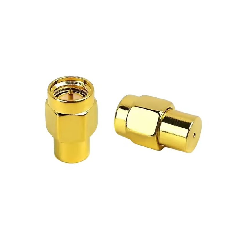
SMA (SubMiniature A) Terminators
- Impedance: 50 Ω
- Frequency Range: DC – 26.5 GHz (precision versions up to 40 GHz)
- Use Case: RF testing, antennas, microwave devices
- Advantages: Excellent repeatability and high frequency precision
- Sino-conn Design: Stainless steel body, gold-plated pin, optional 2 W or 5 W power ratings
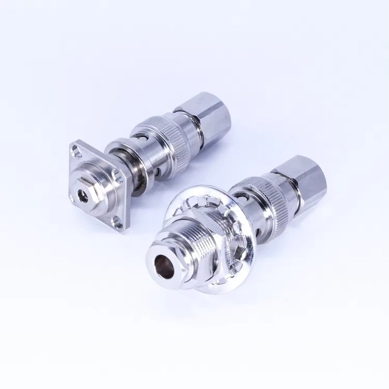
N-Type Terminators
- Impedance: 50 Ω
- Frequency Range: DC – 18 GHz
- Use Case: Outdoor RF, base stations, high-power test racks
- Advantages: Threaded coupling, robust, weather-resistant
- Sino-conn Design: IP67 waterproof sealing, up to 25 W continuous power handling

TNC and F-Type Terminators
- TNC: Threaded BNC variant for vibration resistance, common in military and mobile communications.
- F-Type: Economical 75 Ω connector for CATV, satellite, and home broadcast systems.

Functional Types:Fixed, Feedthrough, and Switchable Terminators
Different applications require terminators to perform slightly different roles, depending on whether they must absorb, measure, or switch signals.
| Type | Description | Typical Use | Pros | Limitations |
|---|---|---|---|---|
| Fixed Terminator | Resistor permanently mounted in connector housing | RF networks, CCTV lines, unused ports | Compact, stable | Not reusable inline |
| Feedthrough Terminator | Terminator passes signal through while providing matched impedance | Oscilloscopes, analyzers, inline calibration | Enables measurement without distortion | Slightly larger size |
| Switchable Terminator | Built-in switch toggles between termination and through-mode | Laboratory testing, multi-device setups | Flexible and reusable | Higher cost, more mechanical wear |
Sino-conn feedthrough terminators use non-inductive resistors and low-loss dielectric spacers to minimize parasitic capacitance (< 0.2 pF), ensuring linear phase response across wide bandwidths.
Power and Frequency Classifications
Terminator selection depends on both frequency bandwidth and power-handling capacity.
Low-power (≤ 1 W) models suit signal measurement and CCTV, while high-power (10 – 50 W) types are used in transmitters and RF test loads.
| Power Rating | Typical Body Type | Use Case | Thermal Dissipation Design |
|---|---|---|---|
| 0.25 – 1 W | Compact brass or stainless body | Instrument ports, analyzers | Internal resistor + compact heat path |
| 2 – 10 W | Medium housing, SMA or N-type | RF bench testing, calibration | Finned or ribbed metal body |
| 25 – 100 W | Bulk load or dummy load style | Transmitter terminations, high-power RF | Large heat sink, external fins |
Sino-conn employs metal-film and carbon-composition resistive elements with low thermal drift (±0.05 %/°C) and MIL-grade solder joints to ensure stable operation even under high pulse loads.
Environmental and Mechanical Variants
Coaxial terminators also vary in build quality to suit environmental conditions.
- Standard indoor type: Brass body, nickel-plated finish, 0 – 70 °C.
- Industrial outdoor type: Stainless steel, sealed O-ring, – 55 °C to + 155 °C.
- High-vibration type: TNC or N connectors with lock threads and flexible ferrule.
- Miniature type: Micro-SMA or MMCX connectors for PCB and embedded systems.
Application Matching Table
| Application | Recommended Impedance | Connector Type | Frequency Band | Example Model |
|---|---|---|---|---|
| CCTV / Broadcast | 75 Ω | BNC / F-Type | 0 – 3 GHz | SC-BNC75-T |
| RF / Microwave | 50 Ω | SMA / N-Type | 0 – 26.5 GHz | SC-SMA50-T |
| Telecom / Antenna | 50 Ω | N / TNC | 0 – 18 GHz | SC-NT50-HP |
| Instrumentation | 50 Ω | Feedthrough BNC | 0 – 4 GHz | SC-FTB50-1 |
How to Select the Right Coaxial Terminator for Your Application?
To choose the right coaxial terminator, match the system’s impedance (50 Ω or 75 Ω), connector type, frequency range, and power-handling capacity. Also consider environmental factors such as temperature, vibration, and moisture. The ideal terminator provides low VSWR (< 1.15:1), high return loss (> 20 dB), and precise mechanical fit. Sino-conn customizes each terminator’s impedance, material, and plating to ensure maximum performance across RF, video, and measurement systems.
1. Match the System Impedance First (50 Ω vs 75 Ω)
The first rule of selecting a terminator is to match its impedance to the coaxial cable or system.
| System Type | Standard Impedance | Common Cable Models | Typical Use |
|---|---|---|---|
| RF / Microwave | 50 Ω | RG-58, RG-142, RG-400 | Radios, antennas, test benches |
| Video / CCTV / CATV | 75 Ω | RG-59, RG-6 | Cameras, broadcast, HDTV |
| Instrumentation / Oscilloscope | 50 Ω | RG-223, RG-214 | Signal measurement, calibration |
2. Verify Frequency Range Compatibility
Each connector interface and resistor design supports a certain bandwidth.
| Connector Type | Frequency Range | Recommended Applications |
|---|---|---|
| BNC (50 Ω) | DC – 4 GHz | Laboratory, video, instrumentation |
| SMA (50 Ω) | DC – 26.5 GHz (up to 40 GHz custom) | RF, radar, satellite, test systems |
| N-Type (50 Ω) | DC – 18 GHz | Outdoor base stations, telecom |
| F-Type (75 Ω) | DC – 1 GHz | CATV, broadcast video |
If your setup involves broadband or high-frequency testing, choose precision SMA or N-type terminators with non-inductive metal-film resistors to maintain flat response across the range.
3. Consider Power-Handling Capacity
Power handling defines how much RF or electrical energy the terminator can safely absorb without overheating.
| Power Rating | Housing Size | Cooling Type | Typical Use Case |
|---|---|---|---|
| 0.25–1 W | Miniature | Conduction only | Oscilloscopes, analyzer ports |
| 2–10 W | Medium | Convection-cooled body | RF calibration, test benches |
| 25–100 W | Large, finned | Forced air or heatsink | Transmitters, dummy loads |
4. Select the Correct Connector Interface
Connector selection ensures mechanical compatibility and electrical reliability.
- BNC: Fast-connect bayonet, ideal for CCTV and measurement ports.
- SMA: Compact and precise, best for RF and microwave setups.
- N-Type: Rugged, weather-sealed; used outdoors and for higher power.
- TNC: Threaded BNC variant, excellent under vibration.
- F-Type: Economical, 75 Ω, common for home and CATV networks.
Tip:
If your system mixes connector standards (e.g., SMA to BNC), use precision-rated adaptors with consistent impedance to maintain return loss performance.
5. Evaluate Environmental Conditions
A terminator that performs perfectly in a lab may fail in a harsh field environment. Consider:
| Environmental Factor | Standard Type | Industrial / Outdoor Type |
|---|---|---|
| Temperature Range | 0 °C – 70 °C | –55 °C – +155 °C |
| Moisture / Dust | Unsealed | IP54 – IP67 sealed |
| Corrosion Resistance | Nickel plating | Stainless steel / gold-plated |
| Vibration Resistance | Standard BNC | TNC / N-type with threaded lock |
Sino-conn offers marine-grade stainless-steel terminators and O-ring-sealed housings for long-term reliability in military, aerospace, and outdoor telecom environments.
6. Check Mechanical Precision and Durability
A terminator’s mechanical quality directly impacts long-term electrical stability.
- Thread Tolerance: ±0.02 mm for SMA/N connectors.
- Center Contact Alignment: ≤ 0.1 mm axial deviation.
- Mating Cycles: Typically 500+ insertions without degradation. Sino-conn’s products undergo 3-stage mechanical inspection — dimensional, torque, and contact resistance — to guarantee every unit maintains stable connection integrity.
7. Analyze Electrical Performance Parameters
When comparing manufacturers, evaluate key specs beyond impedance:
| Parameter | Ideal Value | Sino-conn Typical |
|---|---|---|
| VSWR (Voltage Standing Wave Ratio) | ≤ 1.15 : 1 | ≤ 1.10 : 1 |
| Return Loss | ≥ 20 dB | ≥ 30 dB |
| Insulation Resistance | ≥ 10 GΩ | ≥ 10 GΩ |
| Contact Resistance | ≤ 5 mΩ | ≤ 3 mΩ |
| Dielectric Withstanding Voltage | ≥ 1000 V | 1200 V typical |
These metrics confirm not only impedance accuracy but also signal linearity and phase stability, which are critical for RF and test-bench systems.
Understand Application-Specific Considerations
| Application | Required Feature | Recommended Terminator Type | Example |
|---|---|---|---|
| RF / Microwave Testing | Wideband, low VSWR | SMA / N-type, 50 Ω | SC-SMA50-2W |
| CCTV / Broadcast | 75 Ω impedance, BNC interface | BNC 75 Ω fixed load | SC-BNC75-T |
| Ethernet 10BASE2 | Matched line ends | BNC 50 Ω fixed | SC-BNC50-0.5 |
| Instrumentation | Feedthrough measurement | BNC 50 Ω feedthrough | SC-FTB50-1 |
| Aerospace / Outdoor RF | Vibration / weather resistant | N-type or TNC stainless | SC-NT50-SS |
Feedthrough terminators allow signal pass-through while providing matched impedance for instruments like oscilloscopes or analyzers, minimizing measurement error.
Sino-conn manufactures both fixed and feedthrough models with custom labeling, enabling easy identification in multi-port systems.
Compliance and Certification Requirements
Professional clients, especially in defense, telecom, or industrial sectors, often require certifications.
Sino-conn terminators comply with:
- UL, ISO 9001, RoHS, REACH, and PFAS-Free standards
- Full COC (Certificate of Conformance) and COO (Country of Origin) documentation
- Lot-level traceability with laser-engraved serial IDs
This ensures global acceptance and hassle-free integration in regulated markets.
How to Install and Maintain Coaxial Terminators Correctly?
To install coaxial terminators correctly, ensure the connector matches the cable type (BNC, SMA, N-type, etc.), clean contact surfaces, and tighten to the manufacturer’s torque specification. Avoid overtightening, which can deform the dielectric. During maintenance, inspect for corrosion, verify impedance with a network analyzer, and store unused terminators in dry, dust-free containers. Proper installation and regular maintenance ensure optimal impedance matching and long-term signal integrity.
1. Preparation Before Installation
Installing coaxial terminators requires precision, cleanliness, and correct torque to maintain impedance integrity and minimize VSWR (Voltage Standing Wave Ratio).
A. Verify Compatibility
Before installation:
- Confirm impedance (50 Ω or 75 Ω) matches the system.
- Ensure connector type matches the port — e.g., BNC for video, SMA for RF.
- Check power and frequency rating to avoid overloading or overheating.
Tip:
For test equipment, always use calibrated precision terminators rated for your frequency band. Sino-conn labels each terminator with frequency and wattage to simplify visual verification.
B. Inspect Physical Condition
Use a magnifier or scope to check:
- No dents or deformation on the connector threads.
- Center pin is straight and concentric.
- Dielectric is free from cracks or burns.
- Surface is clean and free of oxidation or oil.
Sino-conn terminators are shipped with protective dust caps and anti-oxidation coatings to minimize contamination during storage.
C. Clean Mating Surfaces
A simple cleaning routine greatly improves electrical performance:
- Use lint-free swabs and isopropyl alcohol (IPA) to remove dirt.
- For SMA or N-type connectors, apply compressed nitrogen to blow off debris.
- Never use abrasive paper or metal tools that could scratch contact plating.
2. Correct Installation Procedure
Proper installation ensures stable impedance and protects both the terminator and the device port.
A. Hand-Tighten First
Always align connectors carefully and start by hand-threading. Cross-threading or misalignment can permanently damage high-precision connectors.
B. Apply Specified Torque
Once hand-tight, use a calibrated torque wrench to reach the recommended torque:
| Connector Type | Recommended Torque | Notes |
|---|---|---|
| SMA (50 Ω) | 0.45 – 0.57 N·m (4–5 in-lb) | Use smooth torque wrench |
| N-Type (50 Ω) | 1.35 – 1.69 N·m (12–15 in-lb) | Ensure full engagement |
| BNC (75 Ω) | Hand-tight only | Bayonet lock |
| TNC | 0.79 – 1.13 N·m (7–10 in-lb) | Threaded locking type |
Tip:
Over-torquing can deform the dielectric and cause impedance drift. Under-torquing may create micro-gaps that increase reflection and insertion loss.
C. Verify Electrical Contact
After installation, use a continuity tester or network analyzer to confirm:
- Proper connection (low contact resistance ≤ 3 mΩ).
- Impedance stability across the operating band.
- Return loss ≥ 20 dB or VSWR ≤ 1.15:1.
3. Periodic Maintenance and Quality Assurance
Even passive components like terminators require regular inspection, especially in RF and test environments.
A. Cleaning Schedule
| Usage Frequency | Recommended Cleaning | Procedure |
|---|---|---|
| Daily Testing | Weekly | IPA + nitrogen air |
| Fixed Installation | Quarterly | Visual + torque check |
| Outdoor System | Monthly | Clean and reseal O-rings |
Sino-conn recommends using non-residue electrical cleaners and applying a small amount of dielectric grease on the outer threads for connectors exposed to humidity or salt air.
B. Visual and Mechanical Inspection
Every 3–6 months:
- Check for thread wear, plating discoloration, or cracks.
- Measure torque retention — loose threads often signal metal fatigue.
- Inspect the O-ring seals on outdoor models for degradation.
For precision RF test labs, replace SMA-type terminators after 500 – 1000 mating cycles to maintain accuracy.

4. Electrical Verification and Testing
Proper testing validates that the terminator maintains its rated electrical performance over time.
A. Impedance and Return Loss
Use a vector network analyzer (VNA) or time-domain reflectometer (TDR):
- Measure return loss (S11) at critical frequencies (1 GHz, 5 GHz, 10 GHz).
- Compare results to baseline data supplied in Sino-conn’s QC certificate.
- A deviation of more than 2 dB may indicate wear or contamination.
B. Power Dissipation and Temperature Rise
For high-power models:
- Measure case temperature after continuous 10-minute operation at rated load.
- Acceptable rise: ≤ 40 °C above ambient.
- Higher temperatures suggest dust blockage or poor ventilation.
C. Dielectric Breakdown Testing
For safety-critical or aerospace applications, perform:
- DC withstand voltage test (1 kV – 3 kV for 60 s).
- Insulation resistance check (≥ 10 GΩ). Sino-conn terminators are tested at 125 % rated voltage and certified under ISO 9001 + UL quality systems.
5. Environmental Protection and Storage
Proper storage is essential to preserve mechanical and electrical performance.
A. Ideal Storage Conditions
- Temperature: +5 °C – +35 °C
- Relative Humidity: < 60 %
- Environment: Clean, dust-free, non-corrosive atmosphere
B. Handling Guidelines
- Always cap unused terminators to prevent dust entry.
- Avoid stacking or impact that could deform connector threads.
- Keep power terminators away from static sources or magnets.
Sino-conn packages every terminator in anti-static vacuum bags with humidity indicators for long-term storage stability (shelf life ≥ 5 years).
6. Troubleshooting Common Issues
| Symptom | Likely Cause | Solution |
|---|---|---|
| High VSWR (> 1.2) | Loose connection, damaged dielectric | Retighten or replace terminator |
| Overheating | Exceeded power rating | Upgrade to higher-wattage model |
| Corrosion or discoloration | Moisture ingress | Clean, dry, and apply anti-corrosion compound |
| Fluctuating readings in test setup | Internal resistor drift | Replace terminator; verify with VNA |
| Thread wear or wobble | Over-torque or frequent use | Replace connector or use reinforced stainless model |
Conclusion
Signal integrity begins and ends with proper termination. Coaxial terminators may appear minor, but they are the silent guardians of system stability — preventing costly reflection errors, ensuring true power transfer, and extending equipment lifespan.
Sino-conn’s engineering-grade terminators combine tight impedance control, excellent shielding, and robust mechanical construction — all backed by responsive OEM support and global quality certification.
Looking for a reliable coaxial termination partner?
Contact Sino-conn to customize your coaxial terminators or cable assemblies for RF, CCTV, or measurement systems.