 Skip to content
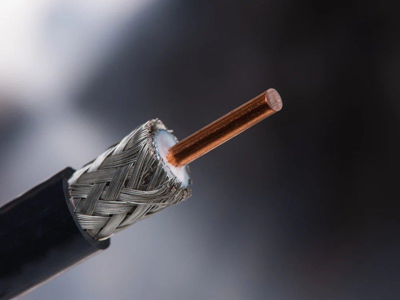
Coaxial cable impedance is a critical parameter in high-frequency signal transmission, affecting every connection in telecom, aerospace, medical, and industrial electronics. Improper impedance can result in signal reflection, insertion loss, and electromagnetic interference, potentially causing system failures or degraded performance. Whether you’re designing a 5G network, a radar system, or medical imaging equipment, understanding impedance is essential to achieving reliable performance.
Coaxial cable impedance is the characteristic resistance to alternating current in the cable, determined by conductor, dielectric, and shield dimensions. Proper impedance ensures minimal reflection, stable VSWR, and low insertion loss, preserving signal integrity in critical applications.
Imagine an engineer installing high-frequency coaxial links in a complex medical imaging system. Even a slight impedance mismatch could distort the signals feeding an MRI scanner, leading to inaccurate imaging results. This article explores the fundamentals of coaxial cable impedance, the factors affecting it, how it’s measured, and how customized assemblies ensure performance under real-world conditions. By the end, you’ll understand what to look for when specifying or purchasing coaxial assemblies from a trusted supplier like Sino-Conn.
What Is Coaxial Cable Impedance?
Coaxial cable impedance is the characteristic resistance to alternating current within a cable, determined by conductor size, dielectric material, and shield geometry. Maintaining precise impedance ensures minimal signal reflection, stable VSWR, and consistent performance across high-frequency applications.
Definition of characteristic impedance
Characteristic impedance (Z₀) is the inherent resistance a coaxial cable offers to alternating current, calculated from the conductor, dielectric, and shield dimensions. It governs how signals propagate and reflects at terminations or mismatched interfaces.

The formula often used for round coaxial cables is:
Z₀ ≈ 138 × log10(D/d) / √εr
Where:
- D = Inner diameter of the shield
- d = Diameter of the center conductor
- εr = Relative permittivity of the dielectric
Accurate impedance ensures that signals travel efficiently with minimal reflection, which is critical for applications such as 5G antennas, MRI machines, or radar systems.
Why impedance matters for signal quality
Impedance mismatches create signal reflection, increasing VSWR and insertion loss. Even small deviations can reduce transmitted power, distort waveforms, or introduce EMI-related issues.
For instance, in a 50 Ω assembly for a 3 GHz telecom application:
- VSWR ≤ 1.2 ensures <5% signal reflection
- Insertion loss ≤ 0.6 dB/m maintains signal strength over standard cable lengths
Sino-Conn ensures impedance is controlled within ±2% for each assembly, preventing reflection hotspots that could disrupt system performance.
Typical impedance values
Common standard impedances:
- 50 Ω: Used in high-frequency RF, telecom, medical, and aerospace systems. Optimized for power handling and minimal reflection.
- 75 Ω: Used for broadcast, CCTV, and cable TV applications. Optimized for low insertion loss over long distances.
Non-standard impedances can be produced to meet specialized system requirements, with Sino-Conn providing full CAD verification and testing.
Components influencing impedance
| Component | Material / Parameter | Impact on Impedance |
|---|---|---|
| Conductor | Copper or silver-plated copper, 32–24 AWG | Determines resistance and signal propagation |
| Dielectric | PTFE, foam PTFE, polyethylene | Maintains spacing, controls capacitance |
| Shield | Foil + braided copper, 85–95% coverage | Controls inductance, EMI protection |
| Connector | SMA, N-type, custom | Maintains Z₀ at termination |
| Jacket | TPE, Silicone, PVC | Protects cable, preserves geometry and impedance |

Each element is designed to maintain characteristic impedance across the operating frequency range, even under bending, twisting, and thermal stress.
Real-world client considerations
When selecting coaxial assemblies, clients consider:
- Conductor type and size: Affects signal loss and flexibility
- Dielectric material: Balances high-frequency performance with temperature stability
- Shield design: Ensures EMI protection and impedance consistency
- Connector precision: Prevents reflection and maintains VSWR
- Environmental durability: Jackets must withstand temperature extremes, UV exposure, oils, and chemicals
For example, a 50 Ω coaxial assembly used in a 5G base station maintains VSWR ≤1.2 and insertion loss ≤0.55 dB/m, even after 1,000 bending cycles in tight conduits. Sino-Conn tests every batch for compliance with these parameters, providing clients with specifications, CAD drawings, and verified performance reports.
Understanding Impedance in Practice
- Electrical impact of impedance mismatch Even a small mismatch (e.g., 50 Ω vs 52 Ω) increases VSWR and signal reflection, which can cause up to 2–3% signal loss in critical systems like radar or medical imaging. Sino-Conn uses precise conductor and dielectric dimensions to maintain consistent Z₀.
- Dielectric uniformity and stability Dielectric thickness and relative permittivity are critical. Foam PTFE offers low εr for minimal high-frequency loss, while solid PTFE provides better thermal and chemical resistance. Slight deviations in thickness can affect VSWR and reflection, so Sino-Conn measures each batch to ±0.05 mm.
- Shield geometry and braid tension Shield coverage and braid tension influence inductance and capacitance. A 95% braid plus 100% foil combination ensures EMI protection and impedance stability, even under bending or torsion.
- Connector influence on impedance Connectors can create small discontinuities that affect impedance. Gold-plated contacts, precise machining, and strain relief preserve VSWR and insertion loss over thousands of mating cycles.
- Environmental and mechanical factors Temperature fluctuations, mechanical stress, and chemical exposure can affect conductor, dielectric, or shield geometry. Sino-Conn selects jackets like TPE or silicone and tests cables under bending, torsion, and thermal cycling to ensure stable impedance under all conditions.
Which Factors Affect Impedance in Coaxial Cables?
Coaxial cable impedance is determined by conductor size, dielectric material and thickness, shield coverage, and connector design. Precision control of these factors ensures stable VSWR, low insertion loss, and reliable signal transmission, especially for high-frequency applications like telecom, aerospace, and medical systems.
Conductor diameter and material
The conductor carries the RF signal and directly impacts resistance and impedance. Key considerations:
- Diameter: Larger conductors reduce DC resistance but increase capacitance, influencing Z₀.
- Material: Copper is standard for most applications; silver-plated copper improves conductivity at high frequencies.
- Stranding: Multi-strand conductors increase flexibility for tight routing without sacrificing signal integrity.
Practical Example: A 50 Ω coaxial assembly for a 5G base station might use 32 AWG multi-strand silver-plated copper. This allows the cable to bend through conduit runs without affecting VSWR, while maintaining insertion loss ≤0.55 dB/m at 3 GHz.

Dielectric type and spacing
The dielectric separates the conductor from the shield and controls impedance. Factors affecting Z₀ include:
- Material choice: PTFE, foam PTFE, or polyethylene have different dielectric constants (εr).
- Thickness uniformity: Deviations as small as ±0.05 mm can affect VSWR and reflection.
- Temperature stability: Dielectric constant can change with heat, affecting performance.
Sino-Conn Approach: Each batch undergoes precision thickness measurements and permittivity tests to maintain ±2% impedance tolerance, ensuring consistent performance under operating conditions.
Shielding coverage and construction
Shielding affects impedance, EMI protection, and mechanical stability.
- Foil shields: Provide 100% coverage for high-frequency EMI protection.
- Braid shields: Offer 85–95% coverage and improve mechanical durability.
- Foil + braid combination: Ensures both EMI protection and stable impedance under bending or vibration.
Sino-Conn tests shield coverage and tension during assembly, ensuring >90 dB shielding effectiveness across the operating frequency range, even after bending and environmental exposure.
Connector design and layout
Connectors are critical for maintaining impedance continuity:
- Type selection: SMA, N-type, MMCX, or custom connectors are chosen based on frequency and mechanical requirements.
- Geometry: Contact length, diameter, and plating influence VSWR.
- Strain relief: Angled or latching connectors reduce stress at terminations, preserving impedance over repeated insertion/extraction cycles.
A coaxial assembly with SMA connectors tested at 1–6 GHz retains VSWR ≤1.2 after 1,000 mating cycles, ensuring high reliability for telecom or medical systems.

How These Factors Influence Impedance
- Conductor trade-offs Copper offers low cost and high conductivity but limited flexibility in small diameters. Multi-strand conductors improve flexibility but slightly increase insertion loss at very high frequencies. Sino-Conn balances strand count and plating thickness to maintain VSWR and minimal loss.
- Dielectric performance Foam PTFE provides a lower dielectric constant, reducing high-frequency insertion loss. Solid PTFE offers better chemical and thermal resistance. Minor dielectric variations can shift impedance and VSWR; Sino-Conn tests each batch for uniformity to ±0.05 mm.
- Shielding effect on electrical performance Shielding not only protects against EMI but also impacts inductance and capacitance. Inconsistent braid tension or incomplete foil overlap can create small impedance mismatches. Sino-Conn monitors braid tension and conducts post-bend tests to ensure impedance stability.
- Connector influence Connectors introduce small discontinuities that affect VSWR. Precision machining, plating, and strain relief ensure connectors maintain low reflection and consistent impedance, even in high-frequency systems.
- Environmental and mechanical factors Temperature fluctuations, chemical exposure, or bending can change dielectric and shield geometry, affecting impedance. Jackets like TPE or silicone maintain consistent spacing and mechanical protection. Sino-Conn performs thermal, humidity, and bending tests to verify stable impedance under all conditions.
Practical Example Table
| Factor | Material / Parameter | Impact on Impedance | Sino-Conn Test Approach |
|---|---|---|---|
| Conductor | 32–24 AWG copper or silver-plated | Resistance and signal propagation | Continuity and insertion loss testing |
| Dielectric | Foam PTFE or PTFE, ±0.05 mm | Maintains Z₀ | Thickness measurement and VSWR testing |
| Shield | Foil + 90–95% braid | EMI protection, impedance stability | Shielding effectiveness test post-bend |
| Connector | SMA, N-type, custom | Maintains Z₀ at interface | VSWR & reflection coefficient testing |
| Jacket | TPE, Silicone, PVC | Environmental & mechanical protection | Thermal cycling, bending, chemical exposure |
How Is Impedance Measured?
Coaxial cable impedance is measured using VSWR, reflection coefficient, and insertion loss tests with precision equipment. Accurate measurement ensures minimal signal reflection, stable VSWR, and consistent high-frequency performance across telecom, medical, aerospace, and industrial applications.
VSWR and reflection coefficient testing
Voltage Standing Wave Ratio (VSWR) indicates how closely the cable matches the intended impedance. A VSWR of 1.0 represents a perfect match, while higher values signal reflection and potential signal loss.
Reflection coefficient (Γ) measures the proportion of signal reflected due to impedance mismatch. For instance, a 50 Ω coaxial cable with a reflection coefficient >0.05 can compromise signal integrity in RF systems.
Sino-Conn uses Vector Network Analyzers (VNA) to perform full-frequency sweeps from DC to several GHz, capturing VSWR and reflection across the cable length. Testing is performed under straight and bent conditions to simulate real installation scenarios.

Insertion loss and frequency response
Insertion loss measures signal attenuation along the cable length. Loss depends on conductor material, dielectric type, shielding, and impedance continuity.
Example: A 1-meter 50 Ω assembly may show:
- 0.30 dB at 1 GHz
- 0.55 dB at 3 GHz
- 1.10 dB at 6 GHz
Sino-Conn evaluates insertion loss both in straight and pre-bent configurations to simulate field installation conditions. This ensures consistent performance in applications where mechanical stress or tight routing occurs.
Continuity and electrical verification
Continuity tests confirm that all conductors and shields are properly connected, with no shorts or breaks. Conductor resistance is typically <0.05 Ω/m for 50 Ω assemblies. Automated jigs allow batch-level testing, ensuring all units meet electrical specifications before shipping.
These checks prevent defective assemblies from reaching customers, saving time and ensuring operational reliability.
Test equipment and reporting
Sino-Conn employs:
- Vector Network Analyzers (VNAs): For VSWR and insertion loss measurements.
- Automated continuity testers: For conductor and shield verification.
- Environmental test chambers: For thermal, humidity, and mechanical stress tests.
Each assembly is documented with:
- VSWR curves across frequency ranges
- Insertion loss plots
- Reflection coefficient graphs
- Shielding effectiveness results
- Batch number and CAD reference
Clients receive detailed reports for verification and regulatory compliance.
Practical Impedance Measurement Techniques
- VNAs and frequency sweeps VNAs provide complete S-parameter profiles (S11 for reflection, S21 for transmission) to detect impedance deviations. High-frequency mismatches can significantly impact performance in medical imaging or telecom systems.
- Mechanical stress testing during measurement Cables are bent to minimum recommended radii while measuring VSWR to simulate installation stress. Sino-Conn’s assemblies maintain VSWR ≤1.2 after 1,000 bends at 2× cable diameter.
- Temperature and environmental validation Measurements under varying temperatures (-40°C to +125°C) confirm dielectric and shield stability. Jackets like TPE and silicone preserve impedance under thermal cycling.
- Connector verification Connectors can introduce small impedance discontinuities. Testing includes full assemblies with connectors installed, measuring VSWR and insertion loss at terminations. Precision machining, plating, and strain relief minimize deviations.
- Batch-level quality assurance Sino-Conn performs 100% continuity testing on all units, with representative sampling for high-frequency and mechanical testing. This ensures all assemblies meet electrical, mechanical, and environmental specifications.
- Documentation and traceability Test reports include detailed curves, measured values, and CAD drawings. This enables clients to review, verify, and approve assemblies before field deployment. Traceability ensures compliance with regulatory requirements and supports warranty claims if needed.
Practical Example Table
| Measurement | Frequency | Observed Value | Specification |
|---|---|---|---|
| VSWR | 1 GHz | 1.15 | ≤1.2 |
| VSWR | 3 GHz | 1.18 | ≤1.2 |
| Insertion Loss | 3 GHz | 0.55 dB | ≤0.60 dB/m |
| Reflection Coefficient | 1–6 GHz | <0.05 | ≤0.05 |
| Shielding Effectiveness | 1–6 GHz | 92 dB | >90 dB |
Do Impedance Variations Affect Cable Performance?
Even small deviations in coaxial cable impedance can increase signal reflection, raise VSWR, and reduce insertion loss efficiency. Precise impedance control is essential to maintain signal integrity, minimize EMI, and ensure reliable performance in telecom, medical, aerospace, and industrial systems.
Signal reflection and insertion loss
Impedance mismatches cause part of the transmitted signal to reflect back toward the source, reducing the power delivered to the load. This reflection increases VSWR and can introduce insertion loss.
Example: A 50 Ω coaxial cable with a 52 Ω mismatch increases VSWR to approximately 1.3, resulting in 2–3% signal loss. In high-frequency applications such as radar, 5G networks, or medical imaging, even small reflections can degrade performance. Sino-Conn ensures impedance tolerance within ±2% for critical assemblies to minimize these effects.
EMI susceptibility and signal integrity
Impedance variations can create small discontinuities along the cable that act as unintended antennas, allowing EMI to enter or exit the cable. This can interfere with adjacent devices or the transmitted signal itself. Proper design, consistent dielectric thickness, shield tension, and connector alignment help maintain impedance continuity and protect against EMI.
Sino-Conn tests assemblies under bending, torsion, and environmental stress to confirm shielding effectiveness (>90 dB) while ensuring impedance stability across the frequency range.
Real-world examples
- Telecom systems: A 50 Ω coaxial assembly connecting a base station to a 5G antenna must maintain impedance continuity to prevent reflected power that can reduce signal throughput.
- Medical devices: In MRI and ultrasound machines, impedance mismatch can distort timing signals, affecting image quality and diagnostic accuracy.
- Aerospace applications: Satellite communication cables with impedance variation may introduce signal attenuation over long runs, potentially compromising telemetry and control signals.
- Industrial RF systems: Manufacturing or sensor networks rely on low-loss, low-reflection cables to ensure accurate high-frequency signal transmission.
Impedance Variations and Their Consequences
- VSWR sensitivity Small deviations in impedance significantly affect VSWR. For example, a 50 Ω assembly with a 1–2 Ω mismatch may increase VSWR to 1.3–1.35. VSWR above 1.2 can lead to energy reflection, overheating in amplifiers, and potential damage in sensitive RF equipment. Sino-Conn maintains tight conductor, dielectric, and shield tolerances to minimize VSWR spikes.
- Insertion loss and high-frequency impact At higher frequencies, even slight impedance changes can create measurable insertion loss, affecting signal strength and system efficiency. For instance, a 3 GHz signal may see an additional 0.2–0.3 dB/m loss if impedance deviates from nominal values. Precise dielectric and shield control is critical for high-frequency cable assemblies.
- Connector and termination effects Connectors can slightly alter impedance at the interface. Poorly designed or misaligned connectors introduce reflection points that degrade VSWR. Sino-Conn applies precision machining and strain relief to maintain impedance through the connector junctions, ensuring performance consistency.
- Mechanical and environmental influences Bending, twisting, thermal expansion, or chemical exposure can change dielectric geometry or shield spacing, affecting impedance. Sino-Conn performs pre-bend and thermal cycling tests to confirm that impedance remains within specification under mechanical stress and environmental extremes.
- Documentation and verification Each assembly is delivered with detailed test reports, including VSWR curves, insertion loss, reflection coefficients, and shielding effectiveness. CAD drawings and batch traceability help clients verify compliance and support regulatory requirements.
Practical Example Table
| Factor | Typical Impact | Observed Effect | Sino-Conn Testing |
|---|---|---|---|
| Impedance mismatch | VSWR increase | 1.15 → 1.3 | VNA sweep |
| Conductor tolerance | Insertion loss | +0.2 dB/m at 3 GHz | Continuity & resistance check |
| Dielectric deviation | Reflection | 2–3% signal reflection | VSWR & dielectric measurement |
| Shield deformation | EMI leakage | 5–10% signal degradation | Shielding effectiveness test |
| Connector misalignment | VSWR spike | 1.2 → 1.25 | Insertion/extraction cycles |
Are Coaxial Cable Impedance Values Customizable?
Yes, coaxial cable impedance values can be customized by adjusting conductor diameter, dielectric type and thickness, shield configuration, and connector design. Custom impedance ensures reliable signal integrity, minimal reflection, and optimal performance in specialized telecom, medical, aerospace, and industrial systems.
Adjusting conductor, dielectric, and shield
Coaxial cable impedance depends on the relationship between the conductor, dielectric, and shield. Custom assemblies allow:
- Conductor adjustments: Changing diameter, stranding, or plating to maintain low resistance and flexible routing.
- Dielectric modification: Selecting PTFE, foam, or polyethylene and adjusting thickness to achieve target Z₀.
- Shield configuration: Modifying braid coverage or adding foil layers to stabilize impedance under bending or environmental stress.
Sino-Conn can produce 50 Ω, 75 Ω, or non-standard impedances to meet client-specific system requirements, maintaining VSWR ≤1.2 across operating frequencies.
Connector selection and layout
Connectors play a critical role in maintaining impedance continuity. Customization options include:
- Connector type: SMA, N-type, MMCX, or fully custom connectors matched to device requirements.
- Connector geometry: Adjusted contact length, diameter, and plating for precise impedance.
- Strain relief and routing: Angled connectors or latching mechanisms reduce mechanical stress, preserving impedance under installation bending.
Sino-Conn engineers verify each connector assembly to ensure VSWR, insertion loss, and reflection meet target performance for the intended frequency range.
CAD drawings, prototyping, and client approval
Custom impedance assemblies require precise planning and validation. Sino-Conn provides:
- CAD drawings within 3 days (or 30 minutes for urgent requests).
- Prototype assemblies tested for VSWR, insertion loss, and shielding effectiveness.
- Client approval before bulk production ensures the design meets functional and environmental requirements.
This process allows clients to implement unique cable lengths, bend radii, and connector arrangements without compromising signal quality.

Customizing Impedance for Real-World Applications
- Balancing flexibility and electrical performance For installations requiring tight routing, multi-strand conductors and flexible jackets (TPE or silicone) maintain bend radius while preserving impedance. Sino-Conn adjusts conductor stranding and shield tension to prevent VSWR spikes during repeated bends.
- Dielectric optimization Foam PTFE offers low dielectric constant for high-frequency applications, while solid PTFE provides high temperature and chemical resistance. Cable design balances dielectric selection to meet both electrical performance and environmental durability.
- Shielding for consistent impedance Shielding geometry affects inductance and capacitance. In custom assemblies, foil + braid configuration is optimized for both EMI protection and characteristic impedance stability, even under mechanical stress.
- Connector engineering for impedance continuity Connectors introduce small discontinuities in the signal path. Precision machining, plating, and strain relief design minimize reflections and VSWR, especially in assemblies operating above 3 GHz.
- Verification and quality control Sino-Conn tests each custom assembly for:
- VSWR and reflection coefficient across the operating frequency range
- Insertion loss under straight and bent conditions
- Shielding effectiveness in real-world EMI scenarios
- Environmental durability under thermal cycling, humidity, and chemical exposure
These procedures ensure custom assemblies perform consistently in demanding installations, from medical imaging equipment to aerospace telemetry systems.
Practical Customization Example Table
| Component | Customization | Purpose | Example |
|---|---|---|---|
| Conductor | Diameter, plating, stranding | Low-loss, flexible | 32 AWG silver-plated, multi-strand |
| Dielectric | Type & thickness | Maintain target Z₀ | Foam PTFE, ±0.05 mm tolerance |
| Shield | Braid + foil coverage | EMI protection & impedance stability | 95% braid + 100% foil |
| Connector | Type & geometry | Low reflection, preserve VSWR | SMA angled, gold-plated contacts |
| Jacket | Material & thickness | Mechanical & environmental protection | TPE or silicone, -40°C to +125°C |
Conclusion
Coaxial cable impedance is a defining factor in signal integrity and overall system performance. From conductor selection and dielectric material to shielding geometry and connector precision, every element affects characteristic impedance, VSWR, and insertion loss. Minor deviations can create reflections, reduce power efficiency, or degrade high-frequency signal quality.
Sino-Conn provides custom coaxial cable assemblies with:
- Precision conductor, dielectric, and shield selection
- Connector engineering for impedance continuity
- Rapid prototyping and CAD drawing delivery
- Comprehensive testing for VSWR, insertion loss, and shielding effectiveness
- Documentation for regulatory compliance and client verification
Whether your application is telecom, medical, aerospace, or industrial, Sino-Conn ensures your coaxial cable assemblies meet exact impedance specifications, mechanical durability, and environmental resilience.
Contact Sino-Conn today to request a custom coaxial cable assembly. Our engineering team will provide tailored solutions, CAD drawings, and performance-verified prototypes to meet your system requirements efficiently and reliably.


