Skip to content
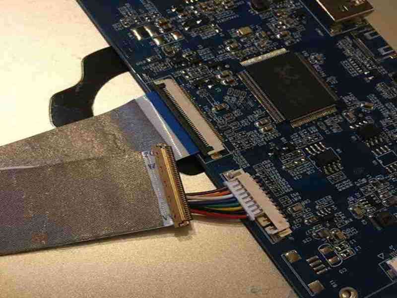
A serializer and a deserializer can look like two small devices placed at opposite ends of a display cable, but their roles shape the entire display architecture. Confusion often starts when a panel datasheet mentions LVDS and the cable is treated as if every LVDS connection were the same. In practice, a short native-LVDS board-to-panel link, an OpenLDI connection, and a remote FPD-Link or GMSL display channel can use very different signal paths even when the final screen is still an LCD or OLED panel.
An LVDS serializer converts wider display data into fewer high-speed differential paths for transmission, while a deserializer receives the serialized signal, restores timing and data, and presents the interface required by the display side. They normally perform complementary functions rather than compete with each other. A separate deserializer is common in remote SerDes links, but it may be unnecessary when a native LVDS panel already contains the receiving function internally.
That distinction matters because many display failures are not caused by an obviously broken wire. A harness can pass continuity testing and still produce flicker, colored lines, intermittent images, or loss of link when pair mapping, impedance, skew, shielding, grounding, connector transitions, or routing are wrong. The useful way to approach the subject is to follow the signal from the processor to the panel, understand what each device is converting, and then treat the cable assembly as part of the transmission channel rather than as a passive bundle of conductors.

What Is an LVDS Serializer and Deserializer?
An LVDS serializer converts wider display data into a smaller number of high-speed differential transmission paths, while a deserializer receives the transmitted stream and reconstructs data and timing for the display side. They perform opposite but complementary jobs. In native-LVDS panels, the receiving function may already be integrated into the panel electronics, so a separate deserializer IC is not always present.
What Does an LVDS Serializer Do?
A serializer normally sits close to the processor, graphics controller, FPGA, or other device that generates the image. In a traditional display architecture, it may accept parallel RGB data and serialize groups of bits onto multiple LVDS differential pairs. A common 24-bit OpenLDI-style arrangement uses four LVDS data pairs plus one differential clock pair, although exact mapping, channel count, and color depth depend on the panel and serializer. The point is not simply fewer wires; the serializer preserves pixel order, channel mapping, timing, polarity, and the electrical conditions expected by the receiving side.
In a remote-display architecture, the same word “serializer” can describe a more sophisticated device. It may accept MIPI DSI, OpenLDI, RGB, or another local interface and translate that information into a proprietary high-speed transport used by FPD-Link, GMSL, or a similar family. The serializer may also carry control traffic, GPIO, diagnostics, or other sideband information. For that reason, the correct device is selected from the complete system: source interface, required bandwidth, cable channel, receiving device, diagnostics, and the mechanical environment all need to agree.
What Does an LVDS Deserializer Do?
A deserializer operates at the receiving end of a serialized link. It detects the incoming high-speed waveform, restores the timing reference, reconstructs transmitted data, and provides an output that the downstream display electronics can understand. Depending on the device family, that output might be OpenLDI/LVDS, parallel RGB, MIPI DSI, or another local interface. Modern devices may also include equalization, link status, error reporting, GPIO transport, and configuration functions that help the system maintain a usable link under real cable loss and noise conditions.
The receiving function becomes especially important as cable length, connector count, data rate, and electromagnetic exposure increase. The waveform arriving at the deserializer is not a perfect copy of the transmitter output; it has already accumulated attenuation, reflections, jitter, common-mode disturbance, and any discontinuities introduced by connectors and assembly geometry. A cable can therefore show correct continuity and still leave too little eye opening or timing margin for stable recovery. That is one reason high-speed display troubleshooting must look beyond resistance measurements.
Are Serializer and Deserializer Alternatives?
Serializer and deserializer devices are usually not alternatives because they solve different problems at opposite ends of a link. In a true point-to-point SerDes architecture, the serializer prepares the source data for transmission and the deserializer reconstructs it at the remote end. Choosing one instead of the other would be similar to replacing a transmitter with a receiver. What often creates confusion is that a native LVDS panel may already contain LVDS receiver and decoding circuitry, so there is no separate device on the display board labeled “deserializer.”
The practical question is therefore not whether one device is better, but whether the receiving function already exists in the target display. If a processor outputs parallel RGB and the panel accepts LVDS, an external serializer may be enough. If the processor and display are connected through a dedicated remote transport such as FPD-Link or GMSL, a compatible serializer and deserializer are normally required. The table below separates the roles without assuming that every LVDS system uses the same architecture.
| Item | Serializer | Deserializer |
| Typical position | Near processor, GPU, ECU, or video source | Near remote display or display bridge |
| Main direction | Source data to serialized link | Serialized link to display-side data |
| Primary job | Prepare and serialize data for transmission | Recover timing/data and reconstruct output |
| Typical inputs | RGB, OpenLDI/LVDS, MIPI, or device-specific | High-speed serialized transport |
| Typical outputs | LVDS or proprietary/high-speed serial channel | OpenLDI/LVDS, RGB, MIPI, or device-specific |
| Separate device always required? | No; source may already integrate LVDS/SerDes output | No for native-LVDS panels; usually yes for remote SerDes |

How Do Serializer and Deserializer Work Together?
A serializer and deserializer form the active endpoints of a display transmission path. The serializer converts source-side video into a transport signal, the cable carries that signal, and the deserializer reconstructs it for the display. Reliable operation depends on the complete channel, including PCB traces, connectors, cable geometry, shielding, grounding, termination, and the receiver’s available signal margin under real installation and operating conditions.
How Does Display Data Flow Through SerDes?
A useful way to understand a display SerDes system is to follow one frame through the hardware. The processor generates video through a local interface, the serializer accepts that data and converts it into the link format, and the high-speed channel carries it to the remote side. The deserializer then recovers the data and timing before handing the reconstructed information to the display interface. A simplified path is processor or GPU -> source interface -> serializer -> connector -> cable -> connector -> deserializer -> panel interface -> display.
This sequence explains why a cable can sit between two SerDes devices even though the panel itself receives ordinary LVDS or MIPI DSI. The signal in the long cable does not necessarily match the final panel interface. That distinction is critical when selecting cable impedance, connectors, shielding, and test methods. Calling the entire path “LVDS” can hide the fact that the long link is a proprietary SerDes channel with its own electrical requirements, while the deserializer only converts it back to LVDS close to the panel.
Where Are the Serializer and Deserializer Located?
In a display system, the serializer is usually placed near the SoC, GPU, ECU, FPGA, or display controller that originates the video. Keeping the source-side interface relatively short allows the longer mechanical distance to be handled by a transport channel designed for cable transmission. The deserializer is normally located close to the remote display or display bridge so the reconstructed local interface travels only a short distance before entering the panel electronics. This arrangement is common in automotive displays, industrial HMIs, medical equipment, robotics, and distributed embedded systems.
The words “local” and “remote” can be misleading because they depend on the application. In a display architecture, the serializer is commonly local to the processor and the deserializer is remote near the screen. In a camera architecture, the serializer may be remote at the camera and the deserializer local to the processor. For drawings and cable specifications, labels such as SER side, DES side, source side, and display side are safer because they identify function rather than assuming that every engineering team uses the same local/remote convention.
How Is Clock and Timing Recovered?
High-speed display data only becomes useful when the receiver can determine exactly when each bit should be sampled. Conventional panel LVDS often uses a dedicated differential clock pair alongside several data pairs. In that environment, data-to-clock relationship and pair-to-pair consistency are important. Many remote SerDes systems instead embed timing information into the serial stream and use clock-and-data-recovery circuitry inside the deserializer. The cable is therefore responsible for preserving enough amplitude and timing margin for the receiver to maintain lock and recover the transmitted information reliably.
These two clocking approaches create different cable priorities. A multi-pair native LVDS harness may be sensitive to data-pair mapping, differential skew, data-to-clock timing, and pair length consistency. A higher-speed remote SerDes channel may be dominated more by insertion loss, return loss, jitter, receiver equalization, connector discontinuities, and link-lock margin. In both cases, seeing electrical activity on an oscilloscope does not prove that the channel is healthy. The question is whether the receiver still has enough eye opening and timing margin under the worst expected cable, temperature, bend, and EMI conditions.
What Counts as the Transmission Channel?
The transmission channel is more than the bulk cable. A realistic path can include serializer package routing, PCB traces, coupling components, common-mode components where used, board connectors, cable connectors, the cable itself, a second connector transition, PCB routing on the display board, and finally the deserializer input. Each transition can change impedance or add loss. This matters because the shortest discontinuities are often found at places that are visually treated as simple assembly details, such as stripped wire length, shield termination, connector launches, or overmold transitions.
A cable manufacturer therefore needs more than a connector photo and pin count when the project carries high-speed display data. The design review should identify the actual transmitter and receiver, target channel, cable length, connector series, pair or coax structure, shield strategy, and test requirement before the drawing is frozen. This is particularly important when a prototype works with a short laboratory cable but the production harness becomes longer, gains another connector, routes near a noisy power stage, or is forced into a tighter installed bend.

Which Display Systems Need One or Both?
A native-LVDS display may need only a serializer at the source because the panel already contains LVDS receiving circuitry. A remote display usually uses both a serializer and a compatible deserializer. The decision depends on the source interface, panel interface, required distance, link bandwidth, diagnostics, EMI environment, connector strategy, and whether the selected transport technology is intended for a cable-length connection.
Do Native LVDS Panels Need a Deserializer?
Not necessarily as a separate component. Many LCD modules that accept an LVDS or OpenLDI-style input contain the receiving circuitry internally. If the processor already provides the correct LVDS output, the signal path may simply be processor -> LVDS cable -> panel. If the processor instead outputs parallel RGB, an external serializer can convert that wide local bus into the LVDS format expected by the panel. The panel then performs the receiving and reconstruction function without requiring another discrete IC on the cable side.
This is where apparently simple cable requests can become risky. Saying “30-pin LVDS cable” does not define the electrical assembly. Two connectors with the same pin count may use different clock pins, pair assignments, panel power pins, color-depth mappings, dual-channel arrangements, or cable exit directions. A proper cable definition needs the panel part number, board-side connector, panel-side connector, pin table, clock/data pair structure, polarity, ground allocation, power conductors, target length, and shield arrangement before manufacturing can be treated as repeatable rather than trial-and-error.
When Is a Full SerDes Pair Required?
A full serializer-deserializer pair becomes attractive when the native display interface is not suitable for the required physical distance or operating environment. This is common when the screen is remote from the processor, the harness must pass through a noisy vehicle or industrial environment, connector count needs to be reduced, diagnostics are important, or bidirectional control functions need to share the same interconnect. The serializer turns the local video interface into the selected transport, and the deserializer restores a panel-compatible interface at the remote end.
Modern remote-display links often operate at multi-gigabit data rates, but the exact number depends on the selected generation and device family. Examples of 3 Gbps and 6 Gbps forward-link modes are common in established automotive-style SerDes families, while newer platforms can go higher. These rates should never be copied into a generic “LVDS cable” specification. The serializer and deserializer part numbers, cable medium, connector system, equalization capability, and channel limits must be treated together because those items define the actual transmission path.
How Do Local and Remote Display Architectures Differ?
The main difference is not screen size; it is where the transport boundary sits. A local display is close enough that the native display interface can usually be routed directly or through a relatively simple bridge. A remote display intentionally inserts a transport link between the processor and screen. Once that happens, the engineering focus moves from only pin mapping and local differential routing to the complete channel, including connector loss, cable attenuation, return path, shielding, equalization, diagnostics, and installed mechanical routing.
Neither architecture is automatically superior. Adding a sophisticated SerDes pair to a 100 mm internal connection can increase cost and complexity without solving a real problem. Extending a native panel LVDS harness far beyond the conditions used during validation can create equally unnecessary risk. A sound decision begins with physical distance, video bandwidth, EMC conditions, connector count, environmental requirements, serviceability, and the capabilities already built into the processor and display. Those factors determine whether the simplest local connection or a dedicated remote transport is the more robust choice.
| Architecture | Typical Signal Path | Separate SER | Separate DES | Typical Use |
| Native LVDS output | SoC -> LVDS panel | No | No | Short internal display link |
| RGB to LVDS panel | RGB -> SER -> LVDS panel | Yes | No | Local board-to-display conversion |
| Remote SerDes display | SoC -> SER -> cable -> DES -> panel | Yes | Yes | Longer or harsher display link |
| Integrated SerDes module | SoC -> module -> cable -> display module | Integrated | Integrated | System-specific distributed display |
| Bridge-based system | Source -> bridge/SER -> link -> DES/bridge -> panel | Often | Often | Interface conversion plus transport |
Does Cable Length Decide the Architecture by Itself?
Cable length matters, but there is no universal distance at which native LVDS suddenly stops working and remote SerDes becomes mandatory. Channel loss is frequency-dependent and is influenced by conductor geometry, dielectric material, connector transitions, shield structures, PCB routing, bend condition, and receiver equalization. A well-controlled longer channel can outperform a poorly designed shorter one. That is why statements such as “LVDS works up to three meters” are too broad to use as design rules without knowing the actual interface and hardware.
The practical question should be framed around the complete link: What transmitter and receiver are used, what line rate or pixel timing must be carried, what cable construction and impedance are required, how many connectors are in the path, and what validation limits are available? A 300 mm prototype that works on a bench does not prove that a 2.5 m production harness will behave the same after it gains tighter bends, additional connectors, higher temperature exposure, or routing next to switching power electronics.
How Are LVDS and Display SerDes Related?
LVDS is an electrical differential-signaling method, while SerDes describes the functional process of serializing and deserializing data. OpenLDI uses LVDS for display transmission, whereas FPD-Link and GMSL are dedicated SerDes families with their own transport architectures. A system can therefore use an LVDS panel even when the long cable leading to it carries a different SerDes signal with different channel requirements and validation methods.
Is LVDS the Same as SerDes?
No. LVDS, or Low-Voltage Differential Signaling, describes an electrical method in which information is represented by the voltage difference between two conductors. A classic LVDS example uses roughly 3.5 mA of differential drive current into a nominal 100 ohm termination, producing about 350 mV of differential voltage at the receiver. Those numbers are useful for understanding conventional LVDS behavior, but the exact interface requirements still come from the relevant device and system specification rather than from the LVDS acronym alone.
SerDes describes a data-conversion function. A serializer converts a wider or parallel representation into a serialized stream, while a deserializer performs the reverse receiving function. A SerDes implementation can use LVDS-type electrical signaling, but it can also use a different physical layer designed around coax, shielded twisted pair, embedded clocking, equalization, or proprietary encoding. This distinction prevents one of the most common specification mistakes: assuming that every display link containing a serializer must be a generic 100 ohm LVDS cable.
How Does OpenLDI Use LVDS?
OpenLDI is closely associated with the familiar multi-pair LVDS connection used by many LCD modules. A common 24-bit arrangement uses four differential data pairs plus one differential clock pair, with serialized data distributed according to the interface mapping. The exact channel organization can differ between implementations, especially when single-channel and dual-channel panel configurations, color depth, odd/even pixel paths, or vendor-specific pin assignments are involved. For cable development, the functional pair map is therefore more important than the connector pin count by itself.
This explains a frequent production failure. A technician can build a harness in which every pin is connected to the correct numbered pin at the other end, yet the display may still fail if intended differential pair members were split into unrelated conductors or if polarity was reversed within a pair. The cable drawing should identify each functional differential pair, clock pair, ground allocation, power function, and any shield or drain connection. That level of definition allows assembly, inspection, troubleshooting, and later repeat production to work from the same engineering baseline.
How Does FPD-Link Differ from Panel LVDS?
FPD-Link has historical ties to display LVDS, but later generations such as FPD-Link III are better understood as dedicated high-speed SerDes transport links. Instead of carrying several panel-LVDS data pairs and a clock pair through the entire harness, the system can serialize the video into a smaller number of very high-speed channels, send that signal through the long interconnect, and then recreate OpenLDI, RGB, MIPI, or another panel-side interface with a deserializer near the display.
That architectural shift changes what matters in the cable. The long link may be specified as a 100 ohm shielded differential channel or another defined medium rather than as conventional panel LVDS. Insertion loss, return loss, connector launch geometry, shield continuity, and high-frequency termination become central. The fact that the panel ultimately receives OpenLDI does not make the long harness an ordinary OpenLDI cable. The transmission channel should be named and validated according to the serializer-deserializer pair that actually drives it.
How Does GMSL Fit Into Display Systems?
GMSL is another family of remote multimedia SerDes technologies often used when high-bandwidth video needs to travel between separated modules. Depending on the exact generation and device, the physical channel may use 50 ohm coax or 100 ohm shielded twisted pair, and it can include a high-speed forward video path together with lower-rate reverse communication for control and diagnostics. In a display architecture, the serializer is usually near the graphics source and the deserializer is placed close to the screen.
The cable requirement therefore comes from the actual serializer and deserializer rather than from the panel label. Useful project inputs include both device part numbers, cable impedance, target length, connector part numbers, forward-link rate, reverse-channel requirement, shield termination, temperature range, routing constraints, and requested channel tests. When those details are available, a custom assembly can be developed as a defined transmission component. Without them, the phrase “GMSL/LVDS display cable” can conceal two very different electrical layers and create avoidable revisions.
Which Cable Factors Affect an LVDS SerDes Link?
The most important cable factors are impedance, insertion loss, pair skew, connector discontinuities, conductor geometry, shielding, grounding, cable length, and mechanical routing. A high-speed display harness can fail even when continuity is perfect because the receiver depends on the shape and timing of the waveform. The cable should therefore be treated as part of the transmission line, not as ordinary point-to-point wiring.
How Does Impedance Affect the Link?
Conventional LVDS links commonly target about 100 ohm differential impedance, and 100 ohm shielded twisted pair also appears in several remote high-speed systems. Some SerDes architectures instead use 50 ohm single-ended coax. The important point is that the target belongs to the actual interface, not to the word “display.” The complete electrical path should remain within the channel limits defined by the transmitter and receiver, including the bulk cable, connector transitions, PCB launches, stripped conductors, shield termination, and any overmold or splice region.
Impedance discontinuity creates reflections. A cable can measure close to the target over most of its length and still contain a short low- or high-impedance region near a connector. At slower edge rates, that local disturbance may have little effect. At multi-gigabit rates, it can consume useful eye opening and reduce receiver margin. TDR is valuable because it shows impedance versus position and can help locate problems caused by excessive untwist, long conductor tails, poor connector transitions, or geometry changes that are difficult to identify with continuity testing alone.
How Do Cable Length, Loss, and Skew Matter?
Longer cables introduce more loss, and high-frequency components are attenuated more strongly than low-frequency components. The receiver therefore sees a waveform that is not only smaller but also slower and more distorted than the waveform leaving the transmitter. Connector count and cable construction can accelerate that degradation. This is why cable length should be evaluated with the actual line rate, insertion-loss budget, receiver equalization, and connector transitions instead of treated as a standalone pass/fail number.
Skew is the timing difference between signals that are expected to arrive together. Within a differential pair, the positive and negative conductors should have closely matched electrical length; too much intra-pair skew converts some differential energy into common-mode behavior and reduces noise margin. In conventional multi-pair LVDS, pair-to-pair and data-to-clock relationships may also matter. A useful production drawing therefore specifies the timing or matching parameter derived from the interface rather than using vague notes such as “all wires same length” when the electrical requirement is really differential-pair balance.
Which Shielding and Grounding Methods Help?
Shielding can reduce radiation and improve immunity, but more metal does not automatically mean a better high-speed cable. Useful structures include foil, braid, foil-plus-braid, individually shielded pairs, overall shielded twisted pair, micro-coax, drain wires, and conductive wraps. Micro-coax is especially useful in compact high-density display assemblies because each signal conductor has its own controlled surrounding shield structure. Twisted-pair constructions can be equally effective when pair geometry, overall shielding, connector transitions, and the intended return path are properly controlled.
Termination determines whether the shield continues to work at high frequency. A long pigtail adds inductance, an unbonded connector shell can interrupt shield continuity, and a shield that stops well before the connector may leave the most sensitive transition exposed. In suitable systems, low-inductance or circumferential shield termination provides better high-frequency continuity, but the grounding strategy still needs to match the electronics design. The cable manufacturer should not decide arbitrarily to connect both ends or only one end without understanding system ground, chassis, EMC, and safety requirements.
How Does Mechanical Routing Change Signal Performance?
Mechanical installation can change the electrical behavior of a display cable. Tight bends can deform pair spacing or coax geometry, compression can disturb dielectric structure, repeated flexing can damage fine conductors, and strain near the connector can change termination geometry. Routing next to motors, DC/DC converters, switching nodes, or high-current power cables can also increase electromagnetic stress. A cable that behaves well when straight on a bench may become intermittent after it is folded into a narrow enclosure or clamped beside a noisy power section.
The minimum bend radius should therefore come from the actual cable construction and installed environment rather than from a generic rule applied to every LVDS harness. Development samples are most useful when they are tested in representative routing, not only as loose cables. For compact micro-coax assemblies, high-flex display harnesses, or automotive-style STP/coax links, the production drawing should control cable exit direction, strain relief, keep-out zones near the connector, bend location, and any areas where repeated motion could disturb the high-speed geometry.
How Do You Select and Validate an LVDS SerDes Link?
Start by defining the source, receiver, serializer/deserializer part numbers, panel interface, resolution, pixel timing or link rate, cable length, impedance, connectors, shielding, grounding, routing, environment, and validation criteria. Then build a representative prototype and verify both basic electrical correctness and high-speed performance before freezing the production drawing, BOM, test criteria, and assembly process for consistent, traceable repeat manufacturing in production.
Which Interface Specs Must Match?
The first engineering review should identify what exists at both ends of the cable. “LVDS display” is not enough. For a native LVDS panel, useful information includes the motherboard connector, panel connector, panel part number, data pair map, clock pair, single- or dual-channel arrangement, color depth, power pins, control functions, shield connection, and target length. For a remote SerDes system, the exact serializer and deserializer part numbers become essential because they define the physical channel and supported transport features.
Resolution should also be tied to real timing. A 1920 x 1080 display at 60 frames per second contains about 124.4 million active pixels per second. At 24 bits per active pixel, that is roughly 2.99 Gbit/s of active image information before blanking, encoding, protocol overhead, or transport-specific organization are included. This does not mean the cable should simply be rated for 2.99 Gbit/s; it shows why resolution alone is incomplete. Refresh rate, pixel clock, color depth, lane mapping, encoding, and the selected SerDes generation all influence the real channel requirement.
What Should Be Controlled in the Cable Drawing?
A production drawing should define the assembly as both an electrical and mechanical component. Connector manufacturer and exact part number, cable type, differential pair or coax assignment, polarity, shield termination, ground paths, overall length, branch or breakout geometry, connector orientation, cable exit direction, critical stripped lengths, labels, and test criteria should be clear enough that another trained production team can reproduce the design without interpreting an old sample. Version control is equally important because seemingly small material changes can alter high-speed behavior.
For custom development, SINO-CONN typically treats the project input as a combination of connector information, pin mapping, cable structure, signal requirement, mechanical routing, shielding, and validation needs rather than as a connector-to-connector assembly alone. This approach is especially useful when the project starts from a sample or incomplete drawing. The engineering objective is to turn that input into an approved pinout, controlled drawing, material definition, prototype, validation record, and repeatable production baseline before volume manufacturing begins.
| Specification Area | Practical Information to Define |
| Source / Sink | SoC, GPU, serializer, deserializer, panel, or bridge part numbers |
| Video | Resolution, refresh rate, color depth, pixel clock or defined SerDes link rate |
| Connectors | Exact manufacturer P/N, mating side, keying, orientation, cable exit |
| Pin Map | Differential pairs, polarity, clock, power, ground, control, shield/drain |
| Channel | Cable type, nominal impedance, target length, connector count, routing limits |
| Mechanical | Length tolerance, bend radius, strain relief, installed routing, flex condition |
| EMC | Individual/overall shield, grounding approach, shell termination, separation from power |
| Validation | Continuity/open-short, TDR, loss, eye/BER, functional display test as required |
Which Tests Verify Signal Integrity?
Basic electrical inspection remains necessary. Continuity, open/short testing, pinout verification, and polarity checks can catch assembly mistakes that would otherwise make the display fail immediately. Mechanical inspection then verifies connector orientation, cable length, strain relief, and critical dimensions. These controls are appropriate for nearly every production harness, but they do not prove that a high-speed link has acceptable signal integrity. A cable can pass every low-frequency electrical check and still create reflections, excess loss, skew, or unstable receiver lock.
Higher-risk projects should add tests that answer the actual channel question. TDR can reveal differential impedance and locate discontinuities along the assembly. Frequency-domain insertion and return loss can show how the channel behaves across the relevant spectrum. Eye testing, jitter measurement, or BER testing may be appropriate when required by the selected link standard or customer validation plan. The final system test remains especially valuable because it verifies the real serializer, cable, deserializer, firmware configuration, panel, installed routing, and power environment together instead of evaluating each component in isolation.
How Do You Troubleshoot Display Errors?
Troubleshooting should begin with the failure symptom rather than assuming the cable is bad. A completely black screen can result from missing panel power, incorrect pin mapping, a disabled serializer, failed link lock, wrong deserializer configuration, or an open high-speed path. Colored vertical lines or severe image corruption can suggest lane mapping, polarity, clock, or marginal signal integrity. Intermittent flicker often points toward connector instability, cable loss, bend-sensitive damage, poor shield termination, or a receiver operating with very little remaining margin.
A practical sequence is to verify power and enable signals, confirm connector orientation, compare the pin map against the approved drawing, check each differential pair and polarity, inspect serializer/deserializer status, compare the suspect assembly with a known-good short cable, and then use TDR or other channel measurements where appropriate. Intermittent failures should be reproduced under the same bend, temperature, vibration, or routing condition that triggers the problem. The drawing and BOM should only be changed after the root cause is understood, otherwise the team risks replacing one uncontrolled variable with another.
Conclusion
The difference between an LVDS serializer and deserializer becomes much easier to understand when the complete display path is visible. The serializer prepares source-side data for transmission; the deserializer reconstructs that information at the receiving side; and in some native-LVDS panels the receiving function is already integrated, so no separate deserializer is needed. Remote FPD-Link, GMSL, and similar architectures add another transport layer, which means the signal in the long cable may be very different from the interface that eventually reaches the display panel.
For cable development, that distinction has a practical consequence: the correct starting point is not simply “make an LVDS cable.” A stable production assembly begins with the source and receiver, serializer/deserializer part numbers where used, pin mapping, channel impedance, cable type, length, connectors, shielding, grounding, routing, and validation criteria. When those elements are controlled together, prototype behavior is much more likely to carry into volume production. That is also where an experienced cable assembly engineering team adds the most value – by turning a display connection requirement into a channel that can be built, measured, approved, and repeated.
FAQ
Is an LVDS serializer the same as an LVDS transmitter?
The terms are often used closely, but they are not always identical. A traditional LVDS display serializer includes a transmitting function because it converts parallel or wider display data into serialized LVDS differential channels and drives those channels toward the panel. In a broader SerDes system, a serializer may do much more than an ordinary LVDS line driver, including protocol conversion, framing, embedded clocking, diagnostics, GPIO transport, or bidirectional control. The device datasheet and system architecture are therefore more reliable than the informal label used in a schematic or purchasing list.
Does every LVDS display need a separate deserializer?
No. Many native-LVDS LCD modules already include LVDS receiving and decoding circuitry inside the panel electronics. If the processor provides the correct LVDS output, the system may only need the cable between the board and display. If the processor outputs another local interface, an external serializer may be added while the panel still performs the receiving function. A separate deserializer is normally required when the system uses a dedicated remote SerDes transport between the source and display, because that transport must be converted back into the panel-side interface.
What is the difference between LVDS and FPD-Link?
LVDS describes a low-voltage differential electrical signaling method, while FPD-Link is a family of display and multimedia interconnect technologies that use serialization to move data between devices. Early FPD-Link implementations are closely associated with LVDS display transport, but later generations such as FPD-Link III use dedicated high-speed SerDes channels with their own channel requirements. A remote FPD-Link cable should therefore be specified from the serializer/deserializer pair, cable medium, connector system, impedance, and channel limits rather than assumed to be interchangeable with a conventional multi-pair panel LVDS harness.
Can LVDS signals run over long cables?
They can operate over useful cable lengths, but there is no universal maximum that applies to every LVDS display. Practical length depends on pixel timing or data rate, cable loss, impedance control, connector transitions, pair skew, PCB routing, receiver margin, shielding, and the installed EMI environment. A short poorly terminated cable can fail while a longer carefully controlled link can work reliably. For longer remote displays, designers often choose dedicated SerDes technologies because those systems are engineered around defined cable channels and can provide equalization, diagnostics, and other tools for maintaining margin.
What impedance should an LVDS display cable use?
Conventional LVDS commonly uses a nominal 100 ohm differential environment, and that is a useful starting reference for many panel-LVDS assemblies. It is not a universal rule for every cable described as LVDS or every remote display link. Some SerDes systems use 100 ohm shielded twisted pair, while others use 50 ohm coax. The actual target should come from the transmitter, receiver, connector, and interface specification. The assembly should also control discontinuities at connector launches, stripped conductors, shield terminations, and other transitions rather than focusing only on the bulk cable impedance.
How should an LVDS or display SerDes cable be tested?
Testing should match the risk of the link. Production checks normally begin with continuity, open/short verification, pinout, polarity, connector orientation, and critical dimensions. High-speed projects may add TDR for impedance profile, insertion and return loss for frequency-domain channel behavior, eye or jitter measurements when required, and system-level display validation using the real serializer, deserializer, and panel. The goal is not to run every possible test on every assembly; it is to use enough evidence to prove that the controlled cable design meets the electrical and mechanical requirements of the actual system.