 Skip to content
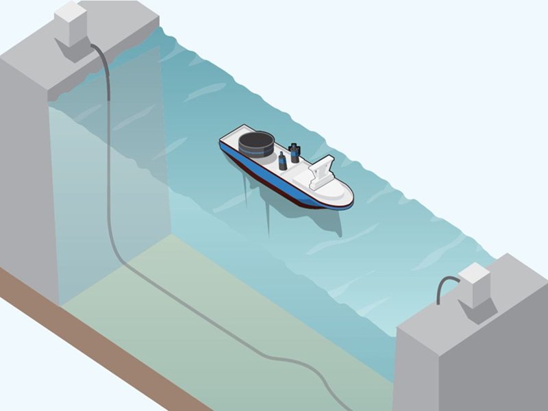
Every time you load a website, join a video call, or send data across continents, you are relying on something most people never see—and rarely think about: undersea internet cables. These cables lie quietly on the ocean floor, crossing thousands of kilometers under extreme pressure, saltwater corrosion, and constant environmental risk. Despite their invisibility, they carry more than 95% of the world’s international data traffic.
Many assume satellites handle global internet communication. In reality, satellites play only a supporting role. The real backbone of global connectivity is a vast, carefully engineered network of submarine fiber optic cables. Understanding how undersea cables are laid reveals not only an impressive engineering process, but also why cable design, documentation, and manufacturing discipline matter far beyond the ocean floor.
Undersea cables are laid using specialized cable-laying ships that carefully deploy fiber optic cables along pre-surveyed seabed routes. Engineers design these cables to withstand pressure, corrosion, and mechanical stress. Near shore, cables are buried for protection, while deep-sea sections rest on the seabed. After installation, cables are electrically tested and monitored throughout their service life to ensure stable global internet connectivity.
The story of undersea cables is not just about oceans and ships—it is about precision engineering, risk control, and system-level thinking. These same principles apply to many industrial and OEM cable assemblies used on land. To understand why, we first need to understand what undersea cables really are.
What Are Undersea Cables?

Undersea cables are specially engineered communication cables, primarily fiber optic, installed on the ocean floor to transmit data between countries and continents. They consist of optical fibers protected by multiple layers designed to resist water pressure, corrosion, and mechanical damage, enabling long-distance, high-bandwidth global communication.
What Is an Undersea Internet Cable?
An undersea internet cable—also known as a submarine communication cable—is a system, not just a wire. It includes optical fibers for data transmission, protective layers, repeaters, and carefully engineered landing points on shore. Unlike ordinary cables, these systems are designed for decades of operation without human access.
The term “internet cable” can be misleading. These cables do not connect individual devices; they connect entire national networks. A single cable may carry traffic for millions of users simultaneously. This scale forces engineers to prioritize reliability over convenience and documentation over assumptions.
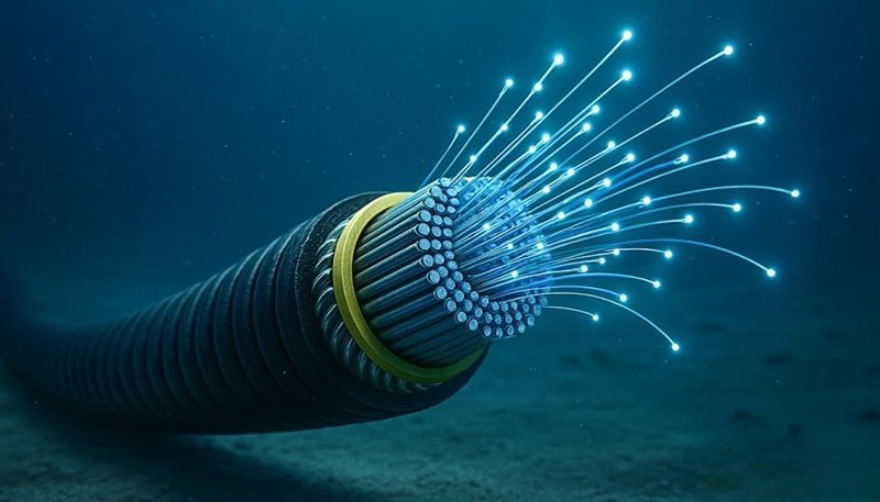
What Are Undersea Cables Made Of?
At the core are optical fibers, chosen for minimal signal loss over long distances. Surrounding the fibers are layers with specific functions:
- Gel or polymer layers for moisture protection
- Copper or aluminum conductors for powering repeaters
- Steel wire armoring for mechanical strength
- Polyethylene outer jackets for corrosion resistance
Each layer is selected based on water depth, seabed conditions, and installation method. Unlike mass-produced consumer cables, undersea cables are custom-engineered per route.
Are Undersea Internet Cables Fiber or Copper?
Modern undersea cables are almost exclusively fiber optic. Copper cables were used in early telegraph systems but cannot support today’s bandwidth or distance requirements. Fiber optics offer:
- Orders of magnitude higher data capacity
- Lower signal attenuation
- Better long-term stability
Copper still appears in undersea cables—but only as a power conductor, not for data transmission.
Why Are Undersea Cables Important for Global Communication?
Undersea cables carry the vast majority of international internet traffic, enabling fast, reliable data transfer between continents. They support cloud computing, financial systems, global trade, and everyday communication at a scale satellites cannot match.
How Much Global Internet Traffic Uses Undersea Cables?
Over 95% of international data traffic travels through undersea cables. This includes:
- Financial transactions
- Cloud data synchronization
- International phone and video calls
- Enterprise network connections
If a major undersea cable fails, the impact can be immediate and visible, especially in regions with limited redundancy.
Why Are Undersea Internet Cables More Important Than Satellites?
| Feature | Undersea Cables | Satellites |
|---|---|---|
| Bandwidth | Extremely high | Limited |
| Latency | Very low | High |
| Stability | High | Weather-dependent |
| Scalability | Modular | Cost-intensive |
Satellites are useful for remote areas, but they cannot replace undersea cables for high-volume, low-latency communication.
How Are Undersea Cables Designed Before Installation?
Before installation, engineers define cable structure, materials, mechanical strength, electrical performance, and environmental resistance based on route surveys and seabed conditions. Each undersea cable is customized for its specific deployment environment.
What Engineering Factors Must Be Considered?
Design begins with route surveys. Engineers analyze seabed topography, temperature, seismic activity, and human risk zones. These factors determine:
- Armoring thickness
- Flexibility requirements
- Outer jacket materials
- Repeater spacing
Ignoring any one factor can shorten cable life or increase failure risk.
How Are Undersea Internet Cables Customized?
Shallow waters require heavy armoring due to anchors and fishing activity. Deep-sea sections prioritize weight reduction and flexibility. This philosophy—design follows environment—is directly applicable to industrial and OEM cable assemblies.
How Are Undersea Cables Laid on the Ocean Floor?

Undersea cables are laid through a carefully planned, tightly controlled engineering process, not through simple deployment or free placement. Every step—from seabed analysis to final testing—is designed to protect long-distance signal performance, mechanical reliability, and decades-long operational stability. The laying process integrates marine engineering, cable design, and real-time installation control into a single coordinated system.
Seabed Survey and Route Planning Before Installation
Before any cable reaches the ocean, engineers conduct comprehensive seabed surveys along the entire planned route. Using sonar mapping, geological sampling, and remotely operated vehicles (ROVs), they evaluate underwater terrain, slopes, sediment type, seismic activity, and areas of human interference such as fishing zones or shipping routes.
The purpose of this stage is not only to choose the shortest route, but to identify the lowest-risk path. Based on survey data, the route is adjusted to avoid sharp drops, rocky areas, and unstable seabed structures. At the same time, engineers define which cable structure will be used in each segment—lightweight designs for deep water and reinforced designs for shallow or high-risk zones.
Controlled Deployment Using Cable-Laying Ships
Once the route and cable design are finalized, specialized cable-laying vessels perform the installation. These ships store the cable in large rotating tanks and release it gradually while moving along the planned seabed path.
During deployment, cable tension, speed, and bend radius are continuously monitored. This control is critical: excessive tension can damage internal fibers, while insufficient tension may cause loops or uneven placement. Modern vessels rely on dynamic positioning systems, GPS navigation, and real-time sensor feedback to maintain precise alignment between the ship and the seabed route.
The cable is never simply “dropped.” It is engineered into position, with every meter laid under controlled mechanical conditions.
Deep-Sea Laying vs. Shallow-Water Burial
Undersea cable installation differs significantly depending on water depth and environmental risk.
| Installation Zone | Typical Method | Main Risks Addressed | Cable Design Focus |
|---|---|---|---|
| Deep Sea (1000m+) | Laid directly on seabed | Pressure, long-term fatigue | Lightweight structure, corrosion resistance |
| Shallow Water / Coastal | Buried below seabed | Anchors, fishing gear, seabed movement | Heavy armoring, abrasion protection |
In deep ocean regions, cables usually rest directly on the seabed, where human activity is minimal. In contrast, near-shore areas require burial, often using underwater ploughs or trenching machines that create a channel for the cable and allow natural sediment to cover it. This burial process significantly reduces the risk of accidental damage.
Real-Time Monitoring During Installation
Throughout the laying process, engineers track key parameters such as deployment speed, cable tension, and curvature. Any deviation from approved limits triggers immediate adjustments. This real-time control ensures the cable is not overstressed during installation—a common cause of early-life failures.
This step highlights a critical engineering principle: installation quality directly affects product lifespan, regardless of how well the cable is manufactured.
Post-Installation Testing and Commissioning
After installation, the cable undergoes end-to-end optical and electrical testing. Engineers measure signal attenuation, continuity, and repeater performance before the system enters service. Only after all parameters meet design requirements is the cable officially commissioned.
This final validation confirms that both the design assumptions and installation execution were correct.

Why Installation Discipline Matters Beyond Undersea Cables
The process of laying undersea cables demonstrates a broader engineering truth: a cable system succeeds only when design, manufacturing, and installation are aligned. Even a perfectly designed cable can fail if routed, bent, or installed incorrectly.
This same principle applies to industrial and custom cable assemblies used in medical devices, automation systems, and OEM equipment. Clear drawings, controlled assembly, and defined installation conditions are essential for long-term reliability—whether the cable is placed on the ocean floor or inside a piece of equipment.
How Are Undersea Cables Tested and Maintained?
After installation, undersea cables are tested for signal integrity and monitored continuously. When faults occur, specialized ships locate and repair damaged sections.
How Is an Undersea Internet Cable Tested?
Engineers perform optical loss measurements, continuity checks, and repeater validation before the system goes live.
How Are Failures Repaired?
| Step | Description |
|---|---|
| Fault Detection | Signal analysis locates failure |
| Recovery | Cable is lifted from seabed |
| Repair | Damaged section replaced |
| Re-deployment | Cable is re-laid and tested |
What Can OEM and Industrial Cable Buyers Learn from Undersea Internet Cables?
Undersea internet cables represent one of the most demanding cable applications in the world. They must operate continuously for decades, cannot be easily accessed after installation, and must tolerate extreme environmental conditions. While most OEM and industrial cable projects are far less extreme, the engineering principles behind undersea cables are directly applicable to custom cable assemblies used in real products.
For buyers, the most important lesson is this: cable reliability is not achieved by material choice alone, but by process discipline—from specification definition and drawing control to manufacturing execution and installation awareness.
System-Level Thinking: Cables Are Not Standalone Parts
One of the biggest takeaways from undersea cable engineering is that cables are treated as system components, not interchangeable commodities. Engineers do not ask only “What cable do we need?” but “How will this cable behave inside the system over time?”
OEM buyers can apply the same mindset by considering:
- How the cable will be routed inside the product
- How it will be bent, fixed, or strained during operation
- How environmental factors such as heat, vibration, oil, or EMI will affect it
This system-level approach reduces late-stage failures and redesign cycles.
Clear Specifications Matter More Than Brand Names
Undersea cables are never defined by brand alone. They are defined by structure, materials, dimensions, and performance limits. This is a critical lesson for OEM and industrial buyers who often focus too early on connector brand names or part numbers.
A well-defined cable specification typically includes:
- Conductor type and size
- Shielding structure and grounding method
- Jacket material and outer diameter (OD)
- Electrical performance limits (voltage, current, impedance)
Without this clarity, pricing, lead time, and performance expectations quickly become misaligned.
Engineering Documentation Prevents Costly Misunderstandings
Every undersea cable project requires strict documentation control. Drawings are approved before production, and no installation proceeds without confirmation. This same discipline applies to successful OEM cable projects.
| Documentation Element | Why It Matters to OEM Buyers |
|---|---|
| CAD → PDF drawings | Ensures both sides agree on structure and pin definition |
| Pinout confirmation | Prevents functional errors and rework |
| Material definition | Avoids compliance or durability issues |
| Revision control | Prevents production based on outdated data |
Projects that skip or rush this step often face delays, quality disputes, or hidden costs later.
Customization Reduces Risk When Done Correctly
Undersea cables are always customized by route and environment. OEM buyers sometimes hesitate about customization, assuming it increases risk. In reality, controlled customization reduces risk when executed by an experienced manufacturer.

Common safe customization points include:
- Cable length and breakout orientation
- Connector alternatives (original vs. equivalent)
- Jacket material selection
- Shielding or grounding adjustments
The key is that customization must be supported by engineering validation—not assumptions.
Installation Conditions Should Influence Cable Design
Undersea engineers design cables with installation in mind: bend radius limits, tension during laying, and long-term mechanical stress. OEM buyers often overlook this step, treating installation as an afterthought.
The table below highlights a common contrast:
| Aspect | Undersea Cable Practice | Common OEM Mistake |
|---|---|---|
| Routing consideration | Defined before manufacturing | Considered after delivery |
| Bend radius limits | Strictly controlled | Ignored or undefined |
| Strain relief | Engineered into design | Added late or omitted |
| Environment exposure | Fully evaluated | Assumed “standard” |
Recognizing installation conditions early leads to more stable and predictable product performance.
Process Discipline Outweighs Unit Cost Optimization
Undersea cable systems are expensive, but failures are far more expensive. This drives a culture where process reliability outweighs short-term cost savings. OEM and industrial buyers can adopt the same principle by balancing price with long-term risk.
A slightly higher unit cost can often:
- Reduce field failures
- Shorten development cycles
- Improve end-product reputation
This mindset is especially valuable in medical, industrial, and mission-critical applications.
Why This Matters When Working with a Custom Cable Manufacturer
The lessons from undersea internet cables reinforce why OEM buyers benefit from working with manufacturers who:
- Ask detailed technical questions
- Provide drawings before production
- Offer multiple solution paths (cost vs. performance)
- Understand installation and system behavior
At Sino-Conn, we apply these principles to every custom cable assembly project—whether it is a single prototype or a production program. By focusing on engineering clarity, controlled customization, and process discipline, we help OEM and industrial customers reduce risk and move from concept to production with confidence.

Final Thoughts: From Ocean Floors to Your Product Design
Undersea cables represent the highest level of cable engineering discipline. While your project may not cross oceans, it likely faces its own challenges—space constraints, EMI control, flexibility, or harsh environments.
At Sino-Conn, we apply the same engineering logic used in large-scale cable systems to custom cable assemblies, whether for industrial, medical, or OEM applications. If you have a drawing, a photo, or even just an idea, our team can help translate it into a manufacturable, reliable solution—quickly and accurately.
Contact Sino-Conn today to request a custom cable solution, drawing, or quotation—starting from 1 piece, with no MOQ.


