 Skip to content
 Antenna Connector Types: A Complete Guide
- andy
Antenna connectors are often treated as small, replaceable hardware items—simple interfaces that “just connect” an antenna to a cable or module. In reality, they are one of the most critical elements in any RF system. A perfectly designed antenna and a high-quality coaxial cable can still perform poorly if the connector in between introduces impedance mismatch, excessive insertion loss, or mechanical instability. Many real-world RF issues—weak signal strength, unstable data rates, inconsistent GPS lock—can be traced back to connector selection rather than the antenna itself.
In modern wireless systems, antenna connectors must support increasingly higher frequencies, tighter space constraints, and harsher operating environments. From compact consumer devices to automotive and industrial platforms, the connector is no longer a passive accessory. It is an active contributor to overall RF performance, mechanical reliability, and long-term system stability.
Antenna connector types are specialized RF interfaces designed to connect antennas to coaxial cables or RF modules while maintaining controlled impedance and signal integrity. Common antenna connectors are classified by interface style, frequency range, application, and mechanical design. Choosing the right antenna connector involves evaluating frequency performance, impedance, cable compatibility, size, durability, and manufacturing constraints. Proper selection reduces signal loss, improves reliability, and ensures stable RF performance.
Behind every antenna connector choice lies a series of engineering trade-offs: frequency versus size, flexibility versus loss, original versus alternative parts, and performance versus cost. Understanding these trade-offs is essential for engineers, OEMs, and buyers who want predictable RF performance rather than trial-and-error results. The sections below break down antenna connector types from a practical engineering and manufacturing perspective, helping you choose with confidence.
What Are Antenna Connectors
Antenna connectors are RF-specific connectors used to interface antennas with coaxial cables or RF modules. They are designed to maintain controlled impedance, minimize signal loss, and preserve shielding continuity across a wide frequency range. Unlike standard electrical connectors, antenna connectors directly affect RF performance, including insertion loss, VSWR, and long-term signal stability.

What Is the Role of an Antenna Connector in RF Systems?
In an RF signal chain, the antenna connector sits directly in the transmission path between the antenna and the RF circuitry. Unlike digital or power connectors, even small mechanical or electrical imperfections at this interface can degrade signal quality. The connector must maintain consistent impedance—typically 50 ohms—while ensuring continuous shielding from the cable to the antenna or module housing.
From a system perspective, the antenna connector also defines where mechanical stress is introduced. Vibration, bending, and repeated mating cycles all concentrate at the connector interface. A well-chosen connector balances electrical performance with mechanical durability, ensuring stable RF behavior throughout the product’s lifecycle.
How Are Antenna Connectors Different from Standard Electrical Connectors?
Standard electrical connectors focus on current capacity and contact resistance. Antenna connectors, by contrast, are optimized for frequency performance. They are sensitive to geometry, plating quality, and shielding continuity. Even small dimensional deviations can impact impedance and reflection characteristics. This is why antenna connectors are specified not only by size and interface, but also by frequency range and RF performance parameters.
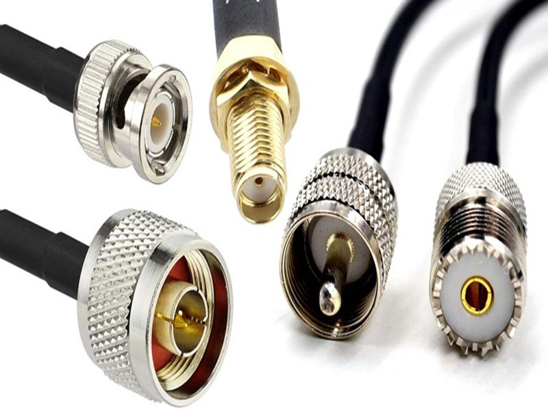
Which Types of Antenna Connectors Are Most Common?
Antenna connectors are not defined by a single global standard. In practice, the most common antenna connector types are shaped by RF performance requirements, mechanical interface design, and real-world application constraints. Rather than memorizing connector names, engineers typically classify antenna connectors by how they mate, where they are used, and what level of RF performance they must support.
Across automotive, industrial, and consumer wireless systems, a relatively small group of antenna connector families accounts for the majority of real deployments. These connectors have become common not because they are “universal,” but because they strike a workable balance between frequency capability, size, durability, and manufacturability.
From an RF cable assembly perspective, antenna connectors are most often grouped into threaded connectors, snap-on connectors, and compact board-to-cable connectors. Each category solves a different engineering problem and carries its own trade-offs.
Threaded Antenna Connectors
Threaded antenna connectors are among the most widely used types in applications where mechanical stability and long-term reliability are critical. The threaded interface provides strong retention force, reducing the risk of accidental disengagement caused by vibration or cable movement.
These connectors are commonly used in automotive, industrial equipment, test instruments, and outdoor antenna systems. Their mechanical robustness makes them suitable for environments where the cable may be routed over longer distances or exposed to repeated stress.
From an RF standpoint, threaded connectors typically offer stable impedance and predictable performance across a wide frequency range. The trade-off is size: threaded connectors are usually larger and require more installation space compared to snap-on alternatives.
Snap-On Antenna Connectors
Snap-on antenna connectors are designed for compact size and fast assembly. Instead of threads, they rely on a push-on mating mechanism, which simplifies installation and reduces assembly time. This makes them very common in consumer electronics, compact wireless modules, and space-constrained designs.
Because snap-on connectors are smaller and lighter, they are often used in devices where internal routing space is limited. However, the reduced mechanical retention means that cable strain relief and routing design become more important to ensure long-term reliability.
In RF cable assemblies, snap-on connectors are typically paired with flexible, small-diameter coaxial cables to minimize mechanical stress at the interface.
Board-Mounted and Module-Level Antenna Connectors
Another common category includes antenna connectors designed to interface directly with PCBs or RF modules. These connectors are widely used in IoT devices, embedded wireless modules, and compact communication systems.
Board-mounted antenna connectors allow antennas or RF cables to be connected or replaced without soldering directly to the board. This improves serviceability and supports modular design approaches. However, these connectors require careful PCB layout and grounding to maintain RF performance, especially at higher frequencies.
How Common Antenna Connectors Are Classified in Practice
Rather than selecting a connector by name alone, engineers often start with a practical classification based on interface style and use case.
Common Antenna Connector Categories by Interface Style:
| Connector Category | Key Advantage | Typical Application Environment |
|---|---|---|
| Threaded | High mechanical retention | Automotive, industrial, outdoor |
| Snap-on | Compact size, fast assembly | Consumer electronics, compact devices |
| Board-mounted | Direct PCB integration | RF modules, IoT, embedded systems |
This classification helps narrow options early in the design process before deeper RF and mechanical parameters are evaluated.
Why No Single Antenna Connector Type Is “Best”
One common misunderstanding among buyers is the idea that there is a universally “best” antenna connector. In reality, the most common antenna connectors became popular because they perform well enough across a range of constraints, not because they are perfect in every scenario.
A connector that works well in a fixed industrial antenna system may be impractical in a compact handheld device. Likewise, a connector optimized for size may not tolerate vibration or repeated mating cycles. This is why antenna connector selection is always contextual.
How This Impacts RF Cable Assembly Design
In RF cable assemblies, the antenna connector cannot be considered in isolation. Its performance depends on how it interfaces with the coaxial cable, how shielding is terminated, and how mechanical stress is managed at the transition point.
Using a common antenna connector type simplifies sourcing and improves compatibility, but only when it is matched correctly with the cable structure and application environment. Many RF performance issues occur not because the connector type is uncommon, but because a common connector was used in an unsuitable way.
Key Takeaway for Engineers and Buyers
The most common antenna connector types are common because they balance RF performance, mechanical reliability, size, and manufacturability. Understanding why these connectors are commonly used—rather than simply knowing their names—helps engineers and buyers make more reliable decisions, especially when working with custom RF cable assemblies.
For projects where connector choice affects signal quality, production yield, and long-term reliability, early clarification of connector type and interface requirements can prevent costly redesigns later in the development cycle.
How Are Antenna Connectors Classified by Frequency and Application?
Antenna connectors are classified by the frequency ranges they support and the applications they serve. Low-frequency applications prioritize mechanical robustness, while high-frequency systems demand precise impedance control and minimal insertion loss. Application-driven selection ensures connectors perform reliably in GPS, WiFi, LTE, and 5G systems.

What Connector Types Are Used for Low vs High Frequency Signals?
As frequency increases, connector geometry becomes more critical. High-frequency antenna connectors require tighter tolerances and smoother signal transitions to reduce reflection and loss. Lower-frequency applications allow more flexibility in connector size and structure but still require stable impedance.
Which Antenna Connectors Are Used in GPS, LTE, WiFi, and 5G?
GPS systems prioritize low loss and stable impedance over relatively narrow frequency bands. WiFi and LTE require connectors that handle broader bandwidths and repeated mating cycles. 5G applications push connectors to higher frequency limits, making precision manufacturing and material selection increasingly important.
What Specifications Matter Most When Choosing an Antenna Connector?
Key specifications include impedance, insertion loss, VSWR, frequency range, mechanical durability, and environmental resistance. These parameters must be evaluated together to ensure the antenna connector performs reliably in the intended application and operating environment.
Which Electrical Parameters Should Be Confirmed First?
Impedance matching is critical—most antenna connectors are designed for 50 ohms. Insertion loss and VSWR determine how much signal is lost or reflected at the connector interface. These values become increasingly important as frequency rises.
What Mechanical and Environmental Factors Affect Connector Selection?
Connector size, mating cycles, temperature tolerance, and vibration resistance all influence long-term performance. Environmental exposure such as moisture or oil may require additional sealing or overmolding.
Key Antenna Connector Specifications
| Category | Key Parameters |
|---|---|
| Electrical | Impedance, VSWR, insertion loss |
| Mechanical | Size, mating cycles, retention |
| Environmental | Temperature, vibration, moisture |
How Do Engineers and OEMs Choose the Right Antenna Connector Type?
In real-world RF projects, antenna connector selection is not driven by a single parameter or a catalog recommendation. Engineers and OEMs typically evaluate connectors through a multi-layer decision process that balances RF performance, mechanical constraints, manufacturing feasibility, cost targets, and supply chain stability. The weight of each factor changes as a project moves from early R&D to mass production.
At the engineering stage, the primary concern is whether the connector can meet electrical performance requirements while physically fitting into the available space. As the design matures, OEMs increasingly focus on whether the same connector can be sourced consistently, assembled reliably, and delivered on time at scale. This is why antenna connector choice is best treated as a system-level decision, not a minor hardware detail added at the end of the design.
Which Is Better RG58 or RG178 for Antenna Cable Assemblies?
RG58 and RG178 are both widely used coaxial cables in antenna cable assemblies, but they are designed for very different physical and electrical priorities. Comparing them purely on signal loss or flexibility often leads to the wrong conclusion unless the application context is clearly defined.
RG58 is a larger-diameter coaxial cable with relatively low attenuation and higher power-handling capability. It is commonly used in applications where cable length is longer, routing space is less constrained, or mechanical robustness is required. The trade-off is reduced flexibility and a larger minimum bend radius, which can be problematic in compact enclosures.
RG178, on the other hand, is designed for compact and lightweight systems. Its small diameter and high flexibility make it suitable for tight routing paths and small devices. However, the thinner conductor results in higher signal loss, especially as frequency and cable length increase. In many compact wireless products, this loss is acceptable because cable runs are short.
RG58 vs RG178 in Practical Antenna Cable Assemblies
| Parameter | RG58 | RG178 |
|---|---|---|
| Cable Diameter | Larger | Smaller |
| Flexibility | Moderate | High |
| Signal Attenuation | Lower | Higher |
| Power Handling | Higher | Lower |
| Typical Application | Longer runs, robust routing | Compact devices, tight spaces |
From an engineering perspective, neither cable is inherently “better.” The correct choice depends on space constraints, frequency range, allowable loss budget, and mechanical routing conditions. Cable and connector selection must be evaluated together, as a connector optimized for a thick cable may not perform reliably when adapted to a thinner one.
How Do Engineers Select Antenna Connectors During R&D?
During the R&D phase, engineers prioritize performance validation and design flexibility over cost optimization. Connector selection at this stage focuses on whether the connector can physically integrate with the antenna, cable, and enclosure while maintaining stable RF performance under expected operating conditions.
Engineers typically assess connector orientation, mating direction, shielding continuity, and routing clearance early in the design. In many cases, initial requirements are incomplete—engineers may only have reference photos, legacy samples, or partial specifications. This makes drawings, rapid prototypes, and small-batch samples critical tools for confirming feasibility.
At this stage, the ability to adjust connector type, cable structure, or termination method often outweighs unit price. A connector solution that allows quick iteration and clear drawing confirmation helps reduce the risk of late-stage redesigns once the mechanical layout is fixed.
What Do OEM Buyers and Assemblers Care About Most?
As a project moves closer to production, OEM buyers and assembly teams shift their focus toward repeatability, supply stability, and total cost control. A connector that performs well in prototypes may still be rejected if it introduces risk during mass production.
OEMs evaluate whether the connector can be sourced reliably over time, whether lead times are predictable, and whether assembly processes are stable at scale. Small variations in connector tolerance, crimp quality, or mating force can significantly impact yield and rework rates in high-volume production.
Rather than selecting the lowest-cost connector, experienced OEMs consider total cost of ownership, including scrap risk, assembly efficiency, inspection requirements, and long-term field reliability.
Engineering vs OEM Priorities in Antenna Connector Selection
| Aspect | R&D Engineers | OEM Buyers / Assemblers |
|---|---|---|
| Primary Focus | Performance & integration | Cost & supply stability |
| Design Flexibility | High | Limited |
| Lead Time Sensitivity | Moderate | High |
| Quality Emphasis | Validation results | Process consistency |
Why This Decision Process Matters
Antenna connector decisions made without considering both engineering intent and OEM production realities often lead to late changes, schedule delays, or unexpected performance issues. Projects that align these perspectives early typically experience smoother transitions from prototype to mass production and more predictable RF performance in the field.
For customers working with custom RF cable assemblies, understanding how engineers and OEMs evaluate antenna connectors helps clarify requirements, reduce miscommunication, and accelerate decision-making throughout the project lifecycle.
Original vs Alternative Antenna Connectors — Which Is Better?
Original antenna connectors offer established documentation and brand recognition, while alternative connectors provide faster lead times and greater flexibility. The optimal choice depends on volume, timeline, and customization needs.
Original connectors are often preferred for locked, high-volume designs. Alternative connectors are well-suited for prototypes, small batches, and custom RF cable assemblies where adaptability is critical.
How Can a Custom RF Cable Assembly Manufacturer Support Antenna Connector Selection?
An experienced RF cable assembly manufacturer supports antenna connector selection through drawings, prototyping, flexible sourcing, and fast turnaround. This reduces design risk and accelerates development.
Supplier capability plays a major role in connector success. Rapid drawings, sample builds, and clear technical feedback allow teams to validate connector choices early and avoid costly redesigns later.

Ready to Specify Your Antenna Connector Solution?
Every RF project has unique requirements. Antenna connector selection should be based on application needs, cable compatibility, and long-term reliability—not assumptions. If you are comparing antenna connector types, evaluating RG58 versus RG178, or building a custom RF cable assembly from drawings or reference photos, Sino-Conn can support you with engineering insight, fast samples, and flexible production.
Contact Sino-Conn to discuss your antenna connector and custom RF cable assembly requirements, request drawings or samples, and move from uncertainty to a validated, production-ready solution.
Related Keywords :antenna connector types, rf antenna connectors, rf cable assembly, rg58 vs rg178, antenna cable selection, rf connector selection, gps antenna connectors, wifi antenna connectors, custom rf cable assemblies, coaxial antenna cable

With over 18 years of OEM/ODM cable assemblies industry experience, I would be happy to share with you the valuable knowledge related to cable assemblies products from the perspective of a leading supplier in China.
manufacturer catalogue
Get A Sample Now From Factory→
Get a quote quickly
Here, developing your OEM/ODM custom cable assemblies collection is no longer a challenge—it’s an excellent opportunity to bring your creative vision to life.


