Skip to content
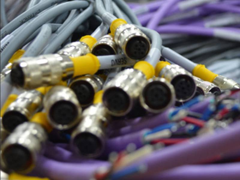
In many OEM projects, cable assemblies are treated as simple components—ordered late, specified loosely, and expected to “just work.” Yet in reality, cable assemblies are often the hidden failure point behind system instability, EMI issues, field returns, and certification delays. A single misinterpreted pinout, shielding gap, or strain relief weakness can compromise an entire product, even if every other subsystem performs perfectly.
The cable assembly process is not merely about cutting wire and attaching connectors. It is a controlled manufacturing workflow that transforms electrical intent into a reliable physical interface—one that must survive installation, movement, temperature, compliance testing, and years of real-world use. For engineers, it is a translation challenge. For procurement teams, it is a risk management decision. For OEM factories, it is where cost, lead time, and quality intersect most visibly.
The cable assembly process is a structured manufacturing workflow that converts electrical and mechanical requirements into finished, tested cable assemblies. It includes design review, material selection, cutting, termination, shielding, inspection, and final testing. A well-controlled process ensures signal integrity, mechanical durability, regulatory compliance, and consistent quality across both prototypes and mass production.
Too often, teams only realize the importance of the cable assembly process after problems appear—during EMC testing, pilot builds, or customer complaints. The sections below break down the process step by step, revealing what really matters at each stage and how experienced suppliers help OEMs avoid costly mistakes before production even begins.
What Is a Cable Assembly Process?
A cable assembly process is the controlled manufacturing workflow used to build finished cable assemblies from raw cables and connectors. It includes requirement clarification, drawing preparation, cutting, stripping, termination, shielding, strain relief, inspection, and testing. A proper cable assembly process ensures electrical performance, mechanical durability, and compliance across both prototype and mass production stages.
What does “cable assembly” really mean in manufacturing?
In manufacturing terms, cable assembly refers to the intentional integration of conductors, insulation, shielding, connectors, and protective elements into a finished unit designed for a specific application.
Unlike bulk cable or loose wire:
- The length is fixed and tolerance-controlled
- The pinout is predefined and verified
- The connectors are application-matched
- The structure is designed to withstand real-world stress
A cable assembly is therefore not a commodity—it is a functional interface component within a larger system.
How is a cable assembly different from simple wire preparation?
Wire preparation typically focuses on:
- Cutting wire to length
- Stripping insulation
- Basic termination
Cable assembly goes much further by addressing:
- Multi-conductor coordination
- Shield continuity and grounding strategy
- Strain relief and mechanical reinforcement
- EMI performance and impedance stability
This difference explains why wire-focused suppliers often struggle with cable assemblies that must pass EMC testing or survive long-term movement.
Why is the cable assembly process considered risk-critical?
From an OEM perspective, cable assemblies are high-risk, low-visibility components.
They:
- Carry power, signals, or data between subsystems
- Are often installed late in the build
- Are difficult or costly to replace after deployment
A weak process can result in:
- Intermittent electrical failures
- EMC test failures
- Early fatigue or connector damage
- Field returns that are hard to diagnose
This is why professional cable assembly processes emphasize process control, documentation, and verification, not just speed.
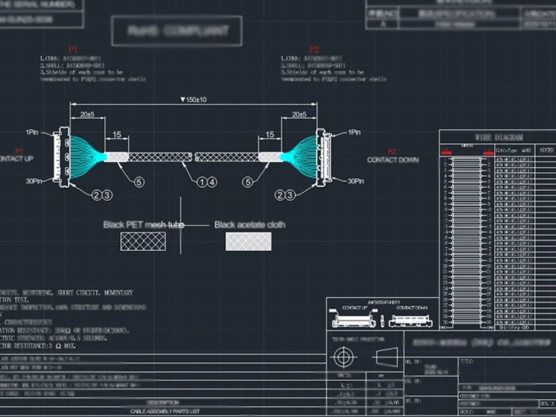
What role do drawings and specifications play in the process?
Drawings are the single source of truth in cable assembly manufacturing.
They define:
- Cable type and construction
- Connector models and orientation
- Pin-to-pin definitions
- Length, tolerances, and labeling
- Shield termination and strain relief structure
At Sino-conn, every cable assembly—whether prototype or mass production—begins with an approved drawing. This prevents misinterpretation when customers provide only photos, part numbers, or partial descriptions.
How does a cable assembly process support consistency at scale?
A proper process ensures that:
- Prototype samples match mass production
- Assemblies remain consistent across batches
- Performance does not drift as volume increases
This consistency is achieved through:
- Standardized work instructions
- Trained operators
- Defined inspection checkpoints
- Traceable materials and components
Without a disciplined process, scaling production often introduces variation—one of the most common OEM complaints.
Why does process maturity matter more than equipment count?
Many buyers assume cable assembly quality depends mainly on machines. In reality, process maturity matters more.
An experienced manufacturer knows:
- Where mistakes are most likely to occur
- Which steps require human verification
- How to balance speed with reliability
Sino-conn’s process maturity is reflected not only in equipment, but in fast drawing response, accurate quoting, flexible customization, and 100% inspection discipline—all of which protect customers from downstream risk.
How Does the Cable Assembly Process Start?
The cable assembly process starts with requirement clarification and engineering review. This includes confirming cable type, connector models, pin definitions, electrical ratings, environmental conditions, and applicable standards. Accurate drawings and specifications are created and approved before production begins, ensuring manufacturability, preventing misinterpretation, and reducing rework, delays, and quality risks later in the project.
What information must be clarified before any production step?
Before production begins, manufacturers must translate customer intent into explicit, testable inputs. These typically include:
- Cable type and construction (single-core, multi-core, coaxial, shielded)
- Length requirements and tolerances
- Connector models (original brand or equivalent)
- Pin-to-pin definitions and orientation
- Electrical parameters (voltage, current, impedance)
- Environmental exposure (heat, oil, UV, movement)
- Compliance requirements (UL, RoHS, REACH, PFAS, etc.)
Many customers initially provide only a part number, photo, or short description. Converting that into a complete specification is the first real value-add step of the cable assembly process.
How are unclear inputs handled in real OEM projects?
In real-world sourcing, buyers often do not fully understand the technical details of the cable they need—especially traders, distributors, or non-engineering purchasers.
A mature cable assembly process includes:
- Reviewing customer-provided photos or samples
- Identifying missing parameters
- Asking targeted clarification questions
- Proposing technically equivalent or improved solutions
At Sino-conn, this step is critical because many projects start from images rather than drawings. Engineering involvement at this stage prevents assumptions that later become costly mistakes.
Why are drawings the foundation of the cable assembly process?
Engineering drawings serve as the single source of truth for cable assembly.
A proper drawing defines:
- Cable and connector part numbers
- Pin assignments and numbering logic
- Exact length and breakout dimensions
- Shield termination method
- Strain relief or overmolding structure
Every cable assembly at Sino-conn—whether a 1-piece prototype or a mass-production order—requires drawing confirmation before production. This ensures both sides are aligned before materials are cut or connectors are terminated.
How fast should drawings and technical feedback be provided?
Speed matters at the beginning because design decisions are still flexible.
In professional workflows:
- Initial drawings are typically provided within 1–3 days
- Urgent projects may require same-day or even 30-minute turnaround
- Revisions are tracked and confirmed before release
Fast response shortens the overall project timeline and allows customers to lock specifications early, reducing downstream delays.
How does connector selection affect the start of the process?
Connector choice directly impacts:
- Lead time
- Cost
- Flexibility in customization
Original-brand connectors often offer brand confidence but may involve:
- Longer lead times
- Limited stock availability
- Less flexibility for minor design changes
Equivalent connectors can:
- Reduce cost
- Improve delivery speed
- Allow faster design iteration
A good cable assembly process presents options, not assumptions—allowing buyers to balance performance, cost, and timeline intentionally.
Why is early engineering review a cost-control tool, not a delay?
Some buyers worry that engineering review slows projects. In reality, it prevents rework.
Early review helps avoid:
- Incorrect pin mapping
- Over- or under-specified materials
- Compliance mismatches
- Late-stage design changes
Fixing these issues before production starts is far cheaper than correcting them after samples fail testing or mass production has begun.
What Are the Key Steps in Cable Assembly Manufacturing?
The key steps in cable assembly manufacturing include cable cutting, stripping, conductor preparation, connector termination, shielding treatment, strain relief or overmolding, assembly finishing, and final testing. Each step must follow defined specifications and work instructions to ensure electrical reliability, mechanical durability, and consistency from prototype to mass production.
Cable assembly manufacturing is often underestimated because the finished product appears simple. In reality, it is a multi-stage precision workflow, where each step introduces potential risk if not properly controlled.
Most cable assembly failures do not happen randomly—they originate from small deviations in one of the key steps below.
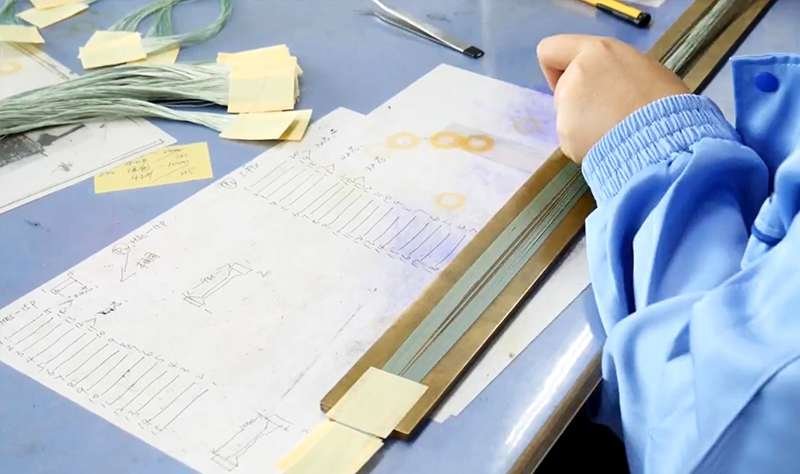
How is cable cutting and length control performed?
Cable cutting is the first physical step—and one of the most overlooked.
Key considerations include:
- Exact finished length (not just nominal length)
- Tolerance control for installation fit
- Compensation for stripping and termination
Inconsistent cutting leads to routing stress, connector pull issues, or installation difficulty. Professional manufacturers use calibrated cutting equipment and documented tolerances to ensure repeatability across batches.
How are cables stripped without damaging conductors or shields?
Stripping is a high-risk step because damage is often invisible.
Proper stripping must:
- Remove insulation cleanly
- Avoid nicking or thinning conductors
- Preserve braid or foil integrity
- Match connector strip-length requirements exactly
Incorrect stripping can pass visual inspection but cause long-term fatigue or intermittent electrical failure. Controlled stripping tools and operator training are essential at this stage.
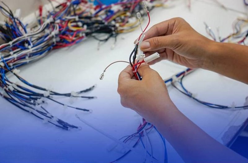
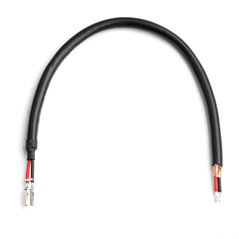
How are conductors prepared before termination?
After stripping, conductors must be prepared correctly before termination.
This may involve:
- Twisting stranded conductors
- Tinning for soldering
- Forming conductors to match connector geometry
Preparation quality directly affects termination strength and electrical stability. Skipping or rushing this step often results in inconsistent crimp height or poor solder wetting.
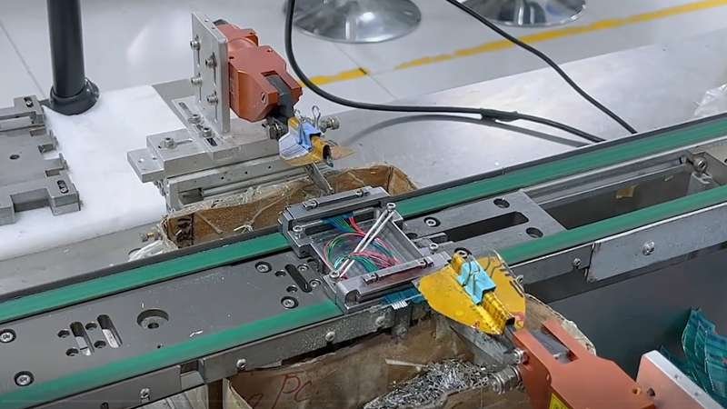
How are connectors terminated and secured?
Connector termination defines the electrical and mechanical integrity of the cable assembly.
Common methods include:
- Crimping (most common in industrial applications)
- Soldering (used for specific connectors or signal requirements)
- IDC termination (for high-density or specific connector types)
Each method requires strict control of:
- Force
- Temperature
- Time
- Tool calibration
Pull-force testing and visual inspection are often applied immediately after termination to confirm reliability before proceeding.
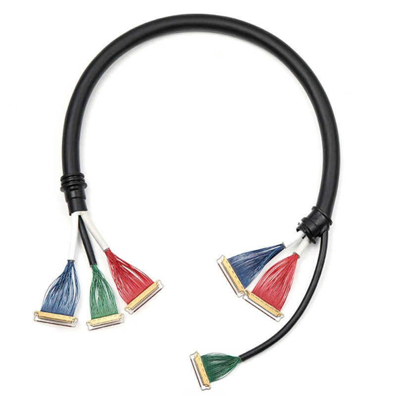
How is shielding handled during cable assembly?
Shielding is not effective unless it is terminated correctly.
Key process elements include:
- Determining grounding strategy (360° termination vs pigtail)
- Ensuring continuous braid or foil coverage
- Maintaining low-resistance contact between shield and connector shell
Improper shielding termination is one of the most common causes of EMC test failure, even when high-quality shielded cable is used.
How are strain relief and overmolding applied?
Strain relief protects the termination point—the most vulnerable part of the assembly.
Common approaches include:
- Heat shrink tubing
- Molded boots
- Full overmolding
The choice depends on:
- Flex requirements
- Environmental exposure
- Cost constraints
Overmolding provides superior durability but requires mold design, material compatibility, and precise process control.
How is final assembly completed before testing?
Once structural steps are complete, assemblies are:
- Cleaned to remove residues
- Labeled or marked if required
- Routed for inspection and testing
At this stage, the cable assembly transitions from manufacturing to verification, where it must prove conformity to the approved drawing.
Key Manufacturing Steps Guide
| Step | Purpose | Typical Risks if Uncontrolled |
|---|---|---|
| Cutting | Dimensional accuracy | Fit issues, routing stress |
| Stripping | Conductor integrity | Hidden damage |
| Preparation | Termination consistency | Weak joints |
| Termination | Electrical reliability | Intermittent failure |
| Shielding | EMI control | EMC test failure |
| Strain relief | Mechanical durability | Early fatigue |
| Final assembly | Consistency | Batch variation |
How Is Quality Controlled During the Cable Assembly Process?
Quality control in the cable assembly process is achieved through multi-stage inspection, including incoming material checks, in-process inspection, electrical and mechanical testing, and final 100% inspection before shipment. Effective quality control prevents hidden defects, ensures compliance with specifications, and guarantees consistent performance from prototypes to mass production.
Cable Assembly Quality Is Built Step by Step, Not Tested at the End
In cable assembly manufacturing, quality cannot be “added” after production.
Unlike standardized electronic components, cable assemblies are highly customized, and a single defect can cause system failure.
This is why professional manufacturers treat quality control as a continuous process, not a final checkpoint.
How are incoming materials inspected before production?
Quality control begins before assembly starts.
Incoming inspection typically covers:
- Cable type, jacket material, and construction
- Conductor count and gauge
- Shielding structure (braid/foil coverage)
- Connector model and plating
- Compliance documentation (UL, RoHS, REACH, PFAS, etc.)
Verifying materials at this stage prevents downstream failures caused by incorrect or non-compliant components—issues that are costly to correct once assembly begins.
What in-process quality controls are applied during assembly?
In-process inspection focuses on preventing defect propagation.
Key checkpoints include:
- Strip length verification after insulation removal
- Conductor integrity inspection (no nicks or thinning)
- Crimp height and crimp force checks
- Solder joint quality (wetting, voids, cold joints)
- Shield termination consistency
By inspecting critical steps immediately, manufacturers reduce scrap, rework, and hidden defects that may not appear in final testing.
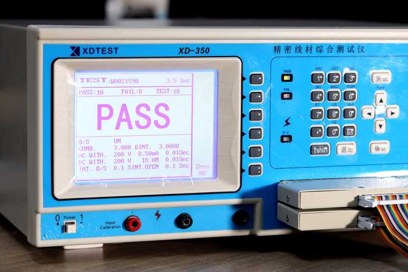
How are electrical tests performed on cable assemblies?
Electrical testing confirms that the cable assembly performs as intended.
Common tests include:
- Continuity testing (correct pin-to-pin connection)
- Short and open detection
- Insulation resistance testing
- Hi-Pot testing for safety-critical applications
These tests ensure electrical integrity and are often performed on 100% of assemblies, not just samples, especially for OEM and regulated applications.
How is mechanical reliability verified?
Mechanical testing ensures that cable assemblies survive real-world use.
Typical checks include:
- Pull-force testing at connector terminations
- Bend or flex testing for dynamic applications
- Connector retention force verification
- Visual inspection for strain relief effectiveness
Mechanical failures often appear only after installation or repeated movement, making these tests essential for long-term reliability.
Why is 100% inspection critical for cable assemblies?
Cable assemblies usually lack redundancy—one failure equals one system failure.
For this reason, Sino-conn applies a three-layer 100% inspection strategy:
- Process inspection – during critical assembly steps
- Finished product inspection – after full assembly
- Pre-shipment inspection – before packing and delivery
This approach ensures every unit shipped matches the approved drawing and specification, not just a statistical subset.
How do documentation and traceability support quality control?
Quality control is incomplete without documentation.
Professional processes include:
- Approved drawings and revision control
- Test records and inspection checklists
- Batch or lot traceability for materials
- Certification alignment for target markets
This documentation supports audits, root-cause analysis, and long-term supplier reliability—especially for medical, industrial, and military customers.
Quality Control Flow Guide
Incoming Material Check ↓ In-Process Inspection ↓ Electrical Testing ↓ Mechanical & Visual Inspection ↓ Final 100% Inspection ↓ Shipment Approval
Each stage eliminates a class of potential failures before they reach the customer.
Common Quality Control Mistakes Buyers Should Watch For
- Relying only on final testing
- Sampling inspection for customized assemblies
- No documented work instructions
- No traceability between drawing and production
These gaps often explain why “the sample was fine, but the mass production failed.”
How Does the Cable Assembly Process Differ by Application?
The cable assembly process differs by application due to variations in electrical performance, mechanical stress, environmental exposure, compliance requirements, and failure tolerance. Industrial, medical, military, and consumer cable assemblies each require different materials, assembly methods, inspection levels, and documentation. Adapting the process to the application is essential to ensure reliability, compliance, and cost efficiency.
How does the process differ for industrial cable assemblies?
Industrial cable assemblies are typically exposed to:
- Continuous vibration
- Mechanical movement or routing stress
- Oil, dust, moisture, or chemicals
- Long operating cycles
As a result, the assembly process emphasizes:
- Thicker or abrasion-resistant jackets
- Robust strain relief and connector retention
- Secure shield termination for EMI stability
- Higher pull-force and bend-cycle requirements
Quality control focuses heavily on mechanical durability, because failures often occur after months of use rather than immediately.
What makes medical cable assembly processes more demanding?
Medical cable assemblies introduce patient safety, hygiene, and regulatory accountability.
Key process differences include:
- Use of biocompatible and sterilization-resistant materials
- Smooth, cleanable surfaces with minimal crevices
- Tight insulation integrity and leakage control
- Enhanced documentation and traceability
Even if the electrical design is simple, the manufacturing process must support repeated flexing, cleaning, and regulatory audits. This significantly elevates process discipline compared to commercial products.
How do military and aerospace applications change the process?
Military and aerospace cable assemblies operate under a near-zero failure tolerance model.
Process characteristics often include:
- Redundant inspections at multiple stages
- Enhanced shielding and grounding strategies
- Strict workmanship standards
- Extended mechanical and environmental testing
In these sectors, cable assembly is treated less as a production activity and more as controlled engineering execution, where documentation, repeatability, and traceability are as critical as performance itself.
Why are consumer cable assemblies processed differently?
Consumer products typically prioritize:
- Cost efficiency
- Visual appearance
- Flexibility and ease of installation
The assembly process is optimized for:
- High throughput
- Simplified termination methods
- Reduced inspection depth
However, applying consumer-grade processes to industrial or medical applications is a common cause of early failure, even when initial samples appear acceptable.

How do compliance and regional standards affect the process?
Different markets impose different requirements:
- UL, RoHS, REACH, PFAS for North America and EU
- Industry-specific safety or performance standards
These requirements influence:
- Material selection
- Testing methods
- Documentation depth
A cable assembly process that ignores regional compliance risks delays, redesigns, or shipment rejection—even if the product itself appears functional.
Why must OEM buyers match process rigor to application risk?
Over-engineering increases cost unnecessarily.
Under-engineering increases failure risk dramatically.
The optimal approach is to:
- Identify real operating conditions
- Understand failure consequences
- Apply just enough process rigor to control risk
This balance is what separates experienced OEM buyers from reactive sourcing decisions.
Application-Driven Process Comparison
| Application Type | Primary Process Focus | Inspection Depth | Failure Risk Tolerance |
|---|---|---|---|
| Consumer | Cost & appearance | Basic | High |
| Industrial | Durability & EMI | Medium–High | Medium |
| Medical | Safety & compliance | High | Very Low |
| Military/Aerospace | Reliability & traceability | Very High | Near Zero |
Why Start Your Cable Assembly Project with Sino-conn
In cable assembly, success is rarely about having the lowest quote or the most machines. It is about making the right decisions early—and executing them consistently.
At Sino-conn, we support OEM customers by:
- Translating incomplete inputs into clear, manufacturable drawings
- Offering flexible connector and material options
- Responding quickly with accurate quotes and engineering feedback
- Delivering fast samples and stable mass production
- Applying three-stage, 100% inspection to every order
Whether you are an engineer validating a new design, an OEM factory balancing cost and volume, or a procurement team managing risk across markets, the cable assembly process should work for your project—not against it.
If you are planning a new cable assembly or need help refining an existing design, reach out to Sino-conn with your drawings, photos, or application details. Our team will review your requirements and propose a solution that aligns performance, cost, and lead time—before problems appear.