 Skip to content
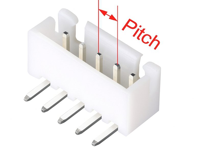
In the world of electronic interconnects, tiny measurements define big outcomes. When engineers design a PCB or cable harness, one small number — the connector pitch — determines whether a plug will fit, signal integrity will hold, and assembly will survive production stresses.
Pitch is one of those details that seems trivial until it causes a prototype to fail or a connector to mis-align by just half a millimeter.
The pitch of a connector refers to the center-to-center distance between adjacent pins, terminals, or contacts. It defines how tightly conductors are spaced, influencing size, voltage tolerance, and compatibility. Connector pitch is critical for ensuring proper mating between connectors, PCBs, and cables — too small a pitch can lead to electrical interference, while too large wastes board space.
Imagine an engineer designing a wearable medical deavice: switching from a 2.54 mm header to a 1.0 mm fine-pitch connector saves half the space — but requires precise cable alignment and special soldering. That’s how connector pitch turns from a simple spec into a crucial design decision.
What Does “Pitch” Mean in a Connector?
When engineers or technicians talk about the pitch of a connector, they’re referring to one of the most fundamental — yet often underestimated — design parameters in electronic interconnects. Pitch determines not only whether two components physically fit together but also how they perform electrically and mechanically in real-world applications.
The pitch of a connector is the center-to-center distance between adjacent pins, contacts, or terminals within a connector housing. It defines the spacing of conductive paths, influencing the connector’s physical dimensions, signal density, voltage rating, and compatibility with mating parts or PCBs. In short, connector pitch determines how tightly circuits are packed — smaller pitches allow miniaturization, while larger pitches improve strength and voltage clearance.
Understanding the Concept of Pitch
In its simplest form, connector pitch measures how far apart one conductive pin is from the next. Imagine a row of pins on a standard header connector — if the first pin’s center to the next pin’s center measures 2.54 mm (0.1 inch), that connector is described as having a 2.54 mm pitch. This spacing repeats consistently along the entire row or grid of contacts.
The concept seems basic, but pitch is what allows connectors to be interchangeable across systems, standards, and manufacturers. A 2.54 mm pitch header from one brand must align perfectly with another brand’s socket of the same pitch; otherwise, even a 0.1 mm deviation can cause electrical shorts or mechanical misalignment.
Why Pitch Matters
Pitch directly influences how dense, durable, and safe a connector is.
- Mechanical Fit: The pitch must match both mating parts (connector to socket or cable) and the printed circuit board (PCB) footprint.
- Electrical Clearance: Larger pitch provides greater spacing between conductors, improving voltage isolation and reducing the risk of arcing or crosstalk.
- Miniaturization: As electronic devices shrink, designers adopt smaller pitches (e.g., 0.5 mm, 0.3 mm) to accommodate more circuits in less space.
- Manufacturability: Connectors with extremely fine pitches require automated assembly and precise alignment, increasing production complexity and cost.
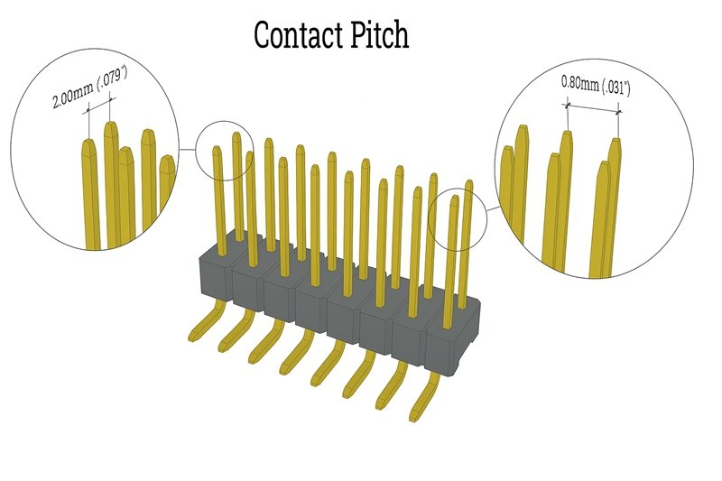
For example, consumer electronics like laptops and cameras use 0.5 mm or 0.8 mm pitch connectors to conserve space, while industrial controllers often use 2.54 mm or 5.08 mm pitch connectors for robustness and easy manual wiring.
The Role of Pitch in Electrical and Mechanical Design
From a design standpoint, pitch defines three critical parameters:
- Contact Density: The smaller the pitch, the more contacts can fit within a given width.
- Insulation Distance: Larger pitch improves voltage endurance and safety.
- Connector Width: Overall connector size scales proportionally with pitch and pin count.
For instance, a 10-pin connector with a 2.54 mm pitch measures about 22.86 mm wide, while a 10-pin connector with a 1.27 mm pitch is only 11.43 mm wide. The same number of pins occupies half the space — a significant factor in compact electronics.
Pitch Consistency and Manufacturing Tolerances
Manufacturers define strict tolerances for connector pitch, typically within ±0.05 mm for fine-pitch connectors and ±0.1 mm for standard models. Even slight inconsistencies during molding, pin insertion, or plating can cause misalignment during mating.
That’s why high-precision connector makers, such as Sino-Conn, use automated inspection systems to measure pin spacing at the micron level. This ensures every connector produced meets exact mechanical and electrical specifications, maintaining full compatibility with mating components and PCBs.
How Connector Pitch Relates to “Connection Pitch”
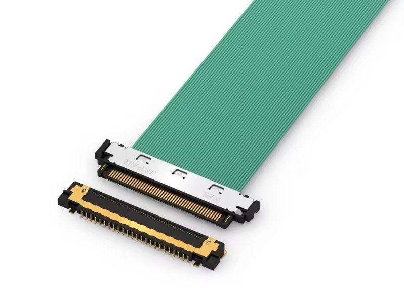
The term connection pitch often describes the spacing at the mating interface between two parts — such as between the pads on a flexible flat cable (FFC) and the contacts inside its ZIF socket. While connector pitch refers to the spacing within the connector itself, connection pitch defines the effective spacing between conductors where electrical contact occurs. In most cases, these two values are identical, but high-speed designs may require slight offsets to maintain impedance balance.
Pitch in Cables and Assemblies
In cable assemblies, pitch defines the conductor-to-conductor spacing inside the cable. Ribbon cables, FFCs, and LVDS harnesses often use 0.3 mm to 2.54 mm pitches to match their corresponding board connectors. The tighter the pitch, the more signal pairs can fit into the same width, but the cable becomes less flexible and more sensitive to noise.
Maintaining consistent pitch across both cable and connector ensures seamless termination and prevents skew or signal reflection — a common cause of EMI in high-frequency designs.
Example Comparison Table
| Pitch (mm) | Connector Type | Typical Voltage Rating (V) | Applications |
|---|---|---|---|
| 0.3 – 0.5 | FFC/FPC | < 30 V | Smartphones, displays, cameras |
| 0.8 – 1.0 | Micro board-to-board | 50 – 100 V | Laptops, IoT devices |
| 1.27 | IDC ribbon | 100 – 150 V | Data harnesses, testing |
| 2.54 | Pin headers / Dupont | 250 V | Industrial electronics |
| 3.96 – 5.08 | Terminal blocks | 300 – 600 V | Power and automotive |
How Do You Measure the Pitch of a Connector?
To measure connector pitch, determine the center-to-center distance between two adjacent pins or contacts. Use a precision caliper, microscope, or optical comparator for fine-pitch connectors. For flexible or multi-pin parts, measure across multiple pins and divide by the number of gaps to minimize error. Accurate pitch measurement confirms connector compatibility, prevents misalignment during soldering, and ensures a reliable mechanical and electrical fit.

Whether you’re an engineer verifying a CAD footprint, a buyer checking samples, or a technician reverse-engineering an unknown connector, these steps apply:
Step 1: Identify the Measurement Points
Locate two adjacent pins or contacts on the same row. The pitch is measured from the center of one pin to the center of the next.
If the pin centers are not visible (e.g., round holes or square blades), measure edge-to-edge and subtract the pin’s width or diameter.
Step 2: Select Proper Tools
Use digital calipers for most connectors above 0.8 mm pitch.
For micro or fine-pitch parts (≤ 0.5 mm), use a microscope, profile projector, or optical comparator to see exact contact centers.
Sino-Conn’s quality lab employs high-resolution optical systems capable of ± 0.01 mm repeatability, suitable even for 0.3 mm FFC connectors.
Step 3: Measure Across Multiple Pins
To reduce human error, measure across several pins:
for example, from the center of pin 1 to pin 10, then divide by 9.
This method averages manufacturing tolerances and gives a more accurate pitch for flexible cables and IDC headers.
Step 4: Record and Convert Units
Most international datasheets use millimeters (mm), but some older connectors are in inches.
- 1 inch = 25.4 mm
- 0.1 inch = 2.54 mm
- 0.05 inch = 1.27 mm Converting units correctly is vital to avoid mismatches between metric and imperial footprints.
Step 5: Verify Against Manufacturer Specifications
Compare your measurement to the product’s datasheet or PCB layout drawing.
If the value differs by more than ± 0.05 mm, re-measure or consult your supplier.
Measurement Example
| Measured Pins | Total Distance (mm) | No. of Gaps | Calculated Pitch (mm) | Typical Connector Type |
|---|---|---|---|---|
| Pin 1 → Pin 2 | 2.54 | 1 | 2.54 | Standard header |
| Pin 1 → Pin 5 | 10.16 | 4 | 2.54 | IDC ribbon |
| Pin 1 → Pin 10 | 11.43 | 9 | 1.27 | Micro IDC |
| Pin 1 → Pin 21 | 10.00 | 20 | 0.50 | FFC /FPC |
| Pin 1 → Pin 31 | 15.00 | 30 | 0.50 | M.2 or LVDS cable |
This averaging method eliminates minor tooling or plating irregularities that can distort single-gap readings.
Common Tools Used in Pitch Measurement
| Tool | Best for Pitch Range | Accuracy | Advantages | Limitations |
|---|---|---|---|---|
| Digital Caliper | ≥ 0.8 mm | ± 0.02 mm | Fast, portable, low cost | Not ideal for micro-pitch |
| Optical Comparator | 0.3 – 2.54 mm | ± 0.01 mm | High precision, visual reference | Requires lab setup |
| Microscope + Scale Reticle | ≤ 0.5 mm | ± 0.01 mm | Excellent for FFC/FPC | Slow manual process |
| CMM (Coordinate Measuring Machine) | ≥ 1.0 mm | ± 0.005 mm | 3-D accuracy for prototypes | High cost, slow |
| Vision Inspection System (Sino-Conn Lab) | All ranges | ± 0.005 mm | Non-contact automatic measurement | Factory-use only |
Tips to Improve Measurement Accuracy
- Clean the Connector – Dust or flux residue can distort readings.
- Use Stable Lighting – Glare makes center points hard to see.
- Measure Multiple Samples – Average across three to five units.
- Check Parallelism – Misalignment of caliper jaws adds 1–2 % error.
- Mind Temperature – Plastics expand slightly; measure near 23 °C for standardization.
Fine-pitch connectors (0.3–0.5 mm) are especially sensitive: a thermal change of only 10 °C can shift readings by ± 0.01 mm due to plastic expansion.
Special Considerations for Cable Assemblies
In flat cables (FFC, LVDS, ribbon), pitch measurement focuses on conductor spacing, not pin spacing.
Use a transparent ruler under magnification to see conductor centers.
Measure from the first to the last visible conductor edge and divide by the number of gaps.
| Cable Type | Typical Pitch (mm) | Tolerance (± mm) | Notes |
|---|---|---|---|
| FFC/FPC | 0.30 – 0.50 | ± 0.03 | Used in displays, touch modules |
| IDC Ribbon | 1.27 – 2.54 | ± 0.05 | For standard headers |
| LVDS Cable | 0.50 | ± 0.02 | High-speed differential pairs |
Accurate cable pitch ensures correct mating with ZIF or IDC connectors and maintains impedance control for high-frequency signals.
Troubleshooting Measurement Errors
| Common Error | Cause | Solution |
|---|---|---|
| Readings vary across samples | Warped plastic or loose pins | Measure multiple connectors; average results |
| Measured pitch too large | Measured from wrong points | Confirm center-to-center reference |
| Data in inches vs. mm | Unit confusion | Convert before comparing |
| Connector doesn’t fit PCB | Wrong pitch family (e.g., 2.0 mm vs. 2.54 mm) | Request Sino-Conn drawing for verification |
What Are Common Connector Pitch Sizes?
In electronic and electrical connector design, pitch size determines the physical spacing, current capacity, and overall density of your connection system. From large, rugged terminal blocks to ultra-fine FPC sockets, every connector type is defined by its pitch — and each pitch family serves a distinct purpose.
Common connector pitch sizes range from 0.3 mm to 5.08 mm, covering ultra-fine FFC/FPC connectors up to heavy-duty power terminals. Smaller pitches (0.3 – 1.0 mm) are used in compact consumer electronics, while medium pitches (1.27 – 2.54 mm) suit signal and data cables. Larger pitches (3.96 – 5.08 mm) handle high-voltage or industrial applications. The correct pitch balances size, current capacity, and mechanical durability for the intended use.
1. Ultra-Fine Pitch (0.3 mm – 0.8 mm)
Used in: smartphones, cameras, wearables, medical sensors, compact PCBs.
Fine-pitch connectors are all about space optimization. A 0.5 mm FFC (Flexible Flat Cable) can carry 30 to 60 conductors in less than 3 cm width, allowing dense signal routing inside slim devices.
| Pitch (mm) | Typical Connector Type | Applications | Current Rating | Key Advantages |
|---|---|---|---|---|
| 0.3 – 0.4 | FFC/FPC, board-to-board | LCD panels, wearables | < 0.5 A | High density, low profile |
| 0.5 | FPC, ZIF socket, M.2 | SSDs, displays, IoT | < 1 A | Ideal for compact modules |
| 0.8 | Micro board-to-board | Compact robotics, sensors | ~ 1 A | Better handling strength |
Design Note:
At pitches below 0.5 mm, alignment precision is critical. Even a 0.05 mm offset can prevent proper mating. Sino-Conn’s precision molding and CAD validation services ensure micro-pitch tolerance control within ± 0.01 mm, guaranteeing perfect fitment.
2. Fine to Medium Pitch (1.0 mm – 1.27 mm)
Used in: signal harnesses, data transmission, compact automation systems.
The 1.27 mm (0.05 inch) pitch family is a global standard for IDC (Insulation Displacement) ribbon connectors, micro headers, and cable assemblies. It’s small enough to save space yet strong enough for automated crimping and repeated mating cycles.
| Pitch (mm) | Typical Connector Type | Applications | Voltage Rating | Common Current |
|---|---|---|---|---|
| 1.0 | Micro headers, mezzanine connectors | Compact PCBs, handhelds | 50 – 100 V | 1 – 1.5 A |
| 1.27 | IDC, D-Sub miniaturized, ribbon | Industrial I/O, sensors, PLCs | 100 V | 2 A |
Industry Tip:
The 1.27 mm pitch is widely used in test fixtures, signal harnesses, and flexible control boards. It’s also a sweet spot for hybrid cable assemblies that mix data and low-power lines — a common Sino-Conn customization for European OEMs.
3. Standard Pitch (2.0 mm – 2.54 mm)
Used in: general electronics, industrial control panels, and prototyping boards.
This category includes the famous 2.54 mm (0.1 inch) pitch, the de-facto standard for headers, jumpers, and pin connectors in breadboards and Arduino-style modules.
| Pitch (mm) | Connector Type | Applications | Voltage Range (V) | Current Range (A) |
|---|---|---|---|---|
| 2.0 | JST, PH-series, Molex Micro-Lock | Automotive sensors, consumer devices | 125 | 2 – 3 |
| 2.54 | Dupont, IDC, pin header | Prototyping, boards, robotics | 250 | 3 – 5 |
Design Note:
2.54 mm pitch connectors are forgiving and easy to hand-solder, making them perfect for prototyping and mid-volume manufacturing. Sino-Conn maintains stocked tooling for both male and female header types, allowing rapid sampling in 2 – 3 days.
4. Large Pitch (3.96 mm – 5.08 mm)
Used in: power transmission, HVAC, automotive, and heavy machinery.
When voltage and current increase, so should the pitch. Wider spacing reduces risk of electrical arcing and improves insulation resistance.
| Pitch (mm) | Typical Connector Family | Typical Current (A) | Voltage Tolerance | Field Example |
|---|---|---|---|---|
| 3.96 | Mini-Fit / terminal block | 8 – 10 | up to 300 V | Power supplies, control units |
| 5.08 | Euroblock / Phoenix type | 10 – 16 | up to 600 V | Industrial PLCs, HVAC modules |
Manufacturing Advantage:
These connectors are easier to assemble manually and can be terminated with thicker gauge wires (AWG 16–20). Sino-Conn’s power-rated connectors use UL94 V-0 housings and tinned copper terminals tested to handle high thermal cycles.
5. Specialized Pitches (M.2, SATA, Automotive, RF)
Some connector families define unique pitch values optimized for speed, form factor, or signal type.
| Connector Type | Pitch (mm) | Use Case | Signal Type |
|---|---|---|---|
| M.2 (NGFF) | 0.5 | SSD, Wi-Fi modules | High-speed PCIe |
| SATA | 1.27 | Data storage | Serial communication |
| Automotive ECU | 2.8 | Vehicle control | Mixed power/signal |
| RF Coaxial | N/A (axial geometry) | Antennas, GPS | RF analog |
| USB-C | Variable (~ 0.5 equivalent) | Consumer devices | High-speed digital |
Note: RF and coaxial connectors don’t define “pitch” in linear spacing but use impedance geometry (e.g., 50 Ω coaxial path).
Sino-Conn manufactures hybrid harnesses that integrate fine-pitch signal connectors with coaxial lines, ideal for automotive cameras and industrial sensors requiring both data and power lines.
6. How Pitch Size Affects Electrical and Mechanical Performance
Pitch not only defines fit but also directly influences electrical insulation, signal crosstalk, and mechanical strength.
| Pitch Range (mm) | Electrical Clearance (V) | Crosstalk Risk | Flexibility | Durability (Mating Cycles) |
|---|---|---|---|---|
| 0.3 – 0.5 | < 30 V | High | High | 20–30 |
| 1.0 – 1.27 | 50–100 V | Medium | Medium | 50–100 |
| 2.0 – 2.54 | 250 V | Low | Moderate | 200–500 |
| 3.96 – 5.08 | 300–600 V | Very low | Low | 500+ |
Fine pitches are prone to EMI and mechanical wear; large pitches improve current handling but require more space. Engineers often balance these trade-offs depending on whether miniaturization or reliability is the higher priority.
7. Regional and Industry Preferences
Different markets and sectors favor certain pitch standards based on their legacy equipment and safety norms:
| Region / Industry | Preferred Pitch Sizes | Rationale |
|---|---|---|
| North America | 2.54 mm, 5.08 mm | Aligns with UL and legacy imperial systems |
| Europe | 3.81 mm, 5.08 mm | Matches DIN rail and terminal block designs |
| Japan / Korea | 1.0 mm, 1.25 mm | Compact consumer electronics |
| Automotive | 2.8 mm, 3.5 mm | High-current signal harnesses |
| Medical / Lab | 0.5 mm, 1.27 mm | Compact PCBs with high signal fidelity |
What Is the Pitch of the M.2 Connector?
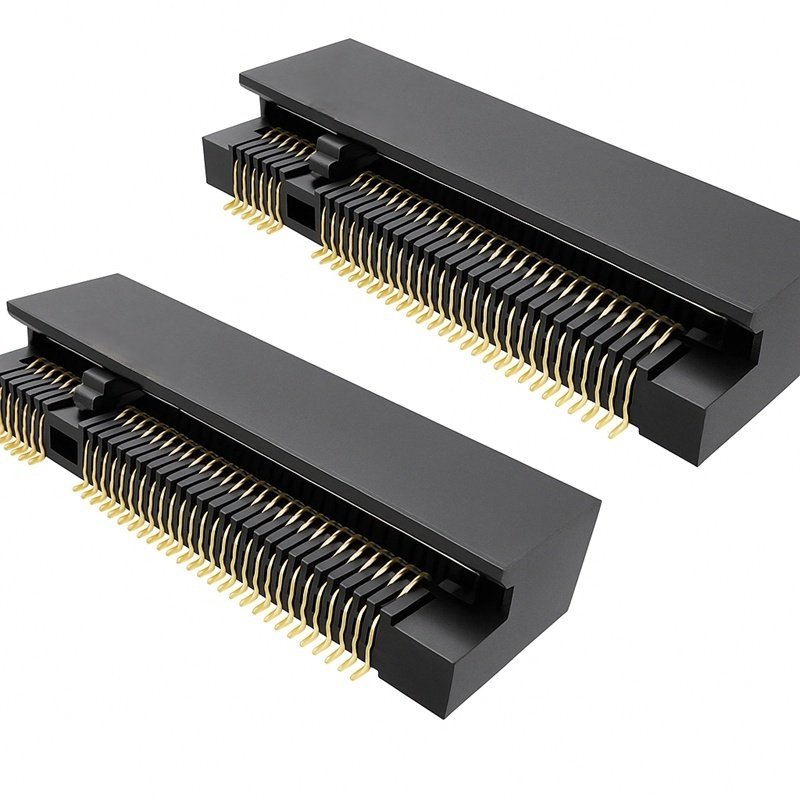
The M.2 connector (commonly used in SSDs and Wi-Fi modules) has a 0.5 mm pitch, allowing up to 67 pins within a compact form. This fine spacing supports high-speed data transmission and power delivery in thin laptops and IoT boards. Such precision requires automated soldering and tight tolerance control — areas where Sino-Conn specializes in custom cable assemblies.
Fine Pitch vs Standard Pitch
Fine-pitch connectors (< 1 mm) offer miniaturization but demand careful handling and controlled solder profiles. Standard pitches (2.0–2.54 mm) remain popular for prototyping and industrial use due to mechanical robustness.
What Is the Difference Between Connector Pitch and Pin Count?
The pitch of a connector refers to the center-to-center distance between adjacent pins, while the pin count represents the total number of conductive terminals within the connector. Pitch determines the connector’s physical size, density, and compatibility with circuit boards, whereas pin count defines how many individual electrical paths it can support. In practice, pitch affects the spacing and mechanical fit of a connector, while pin count determines signal capacity. Together, these two parameters dictate the connector’s overall width, performance characteristics, and application range — for example, a 40-pin connector with a 0.5 mm pitch is much smaller and lighter than a 40-pin connector with a 2.54 mm pitch, even though both carry the same number of signals.
When selecting or designing a connector, both factors must be considered simultaneously. Smaller pitch values are ideal for compact electronics such as displays, sensors, or FFC/FPC assemblies, where high density and limited space are priorities. Larger pitches (e.g., 2.54 mm – 5.08 mm) are preferred in industrial, automotive, and power applications, where higher voltage clearance, mechanical durability, and easier manual assembly are required. Confusing pitch with pin count often leads to mismatched components or PCB misalignment, so engineers typically confirm both parameters through CAD drawings or supplier verification. Sino-Conn supports custom pitch and pin configurations ranging from 0.3 mm to 5.08 mm, ensuring every design achieves the right balance of size, signal capacity, and reliability.
How Does Pitch Affect Connector Performance and Compatibility?
Connector pitch impacts electrical clearance, mechanical strength, and manufacturability. Smaller pitches increase density but reduce voltage tolerance and durability.
| Pitch (mm) | Max Voltage (V) | Crosstalk Risk | Durability | Assembly Ease |
|---|---|---|---|---|
| 0.3–0.5 | ≤ 30 | High | Low | Difficult |
| 1.0–1.27 | ≤ 100 | Medium | Medium | Moderate |
| 2.0–2.54 | ≤ 250 | Low | High | Easy |
| 3.96–5.08 | ≤ 600 | Very Low | Very High | Easiest |
Electrical Impact
Fine pitches improve signal density but increase risk of EMI and dielectric breakdown. Larger pitches provide better insulation and heat dissipation for power applications.
Mechanical and Assembly Impact
Narrow pitches require higher precision in soldering and connector mating. Standard pitches simplify production and rework. Sino-Conn balances these factors by custom-engineering connectors with optimized materials and plating finishes.
How to Choose the Right Connector Pitch for Your Application
Choosing the correct connector pitch is one of the most important design decisions in cable assemblies and PCB interconnections. The pitch determines how tightly contacts are spaced, directly influencing signal integrity, voltage tolerance, durability, and manufacturability. Selecting the wrong pitch can lead to poor mating compatibility, overheating, or signal interference—issues that can affect both performance and safety.
1. Consider Application Size and Space Constraints
For compact electronics such as laptops, smartphones, and camera modules, small-pitch connectors (0.3–1.0 mm) are ideal because they allow more connections within a smaller footprint. However, they require high-precision soldering and are more fragile during assembly. In contrast, larger devices—like control panels or robotic systems—have more space, making 2.0–2.54 mm pitches practical for easier handling and sturdier connections.
2. Evaluate Electrical and Signal Requirements
Pitch selection also depends on voltage, current, and frequency. Smaller pitches increase the risk of signal crosstalk or voltage breakdown, especially at high frequencies or voltages. For high-speed data or low-voltage digital circuits, finer pitches work well. But for power lines or analog circuits, larger pitches (3.96–5.08 mm) provide better insulation and current capacity.
| Pitch (mm) | Signal Type | Voltage Rating | Typical Use Case |
|---|---|---|---|
| 0.3–0.5 | Low-voltage / high-speed | < 30 V | FFC, display modules |
| 1.0–2.0 | Mixed-signal | 50–125 V | Sensor and control cables |
| 2.54–5.08 | Power / industrial | 250–600 V | Power distribution, robotics |
3. Match Connector Pitch with Cable or PCB Layout
Your chosen connector must align with the pitch of mating cables or PCB pads. A mismatch (e.g., 1.25 mm cable with 1.27 mm connector) can cause contact stress, improper fit, or early wear. Always confirm mechanical drawings or request a dimensioned PDF or CAD file from your supplier before ordering. Sino-Conn provides 30-minute drawing verification and custom pitch matching for any connector–cable combination.
4. Assess Durability and Assembly Environment
Industrial and robotic applications face vibration, bending, and temperature changes. Larger pitches allow thicker insulation, higher mechanical stability, and easier manual connection. Fine-pitch connectors, while excellent for miniaturized electronics, are more sensitive to handling and require automated soldering or reflow processes for consistency.
5. Verify Compliance and Manufacturability
For large-scale OEM production, confirm that your selected pitch complies with UL, RoHS, and REACH standards. Standardized pitches like 0.5 mm, 1.27 mm, 2.0 mm, and 2.54 mm are widely supported across connector types, making sourcing and replacement easier. Custom pitches are feasible, but always balance performance benefits with tooling and assembly costs.
Conclusion
Connector pitch may seem like a small detail, but in reality, it defines the precision, compatibility, and reliability of your entire interconnect system. Even a 0.1 mm difference in pitch can cause soldering errors, misalignment, or inconsistent signal transmission — all of which can compromise product performance. Understanding the relationship between pitch and pin count allows engineers and buyers to design more efficient assemblies, reduce manufacturing issues, and ensure long-term electrical integrity across every connection point.
At Sino-Conn, we specialize in helping customers achieve that precision. Our engineering team offers custom pitch options from 0.3 mm to 5.08 mm, rapid CAD-to-prototype turnaround, and strict ±0.01 mm tolerance control for every connector. Whether you’re designing compact FFC assemblies or robust industrial harnesses, we’ll verify your drawings, optimize your connector design, and deliver assemblies that meet global standards like UL, RoHS, and REACH.

Contact Sino-Conn today to discuss your project — because when it comes to connector design, accuracy in every millimeter means reliability in every connection.


