Skip to content
Modern audio systems are far more demanding than most people realize. What listeners experience as “clear sound” or “stable monitoring” is often the result of dozens of small engineering decisions working quietly in the background. Among these, the cable connecting an in-ear monitor (IEM) to its source is one of the most underestimated components. Many audio problems blamed on drivers, DACs, or wireless interference are actually caused by the cable itself—its structure, shielding, flexibility, or connector integrity.
The term “DCP IEM cable” usually appears when buyers are trying to describe a specific IEM cable they already have, saw in a photo, or heard referenced by an engineer. In many cases, the customer does not fully understand what “DCP” stands for. What they do know is that the cable behaves differently from a generic earphone wire: it may be quieter, more flexible, more durable, or better suited for professional monitoring. This gap between terminology and real function is exactly where confusion—and costly mistakes—often start.
A DCP IEM cable typically refers to a custom in-ear monitor cable assembly designed for low-noise audio transmission, high flexibility, and stable connector performance. Rather than a single industry standard, “DCP” usually describes a specific cable structure, conductor layout, or custom specification used in professional audio, stage monitoring, or OEM applications. These cables are often built to order, with defined pinouts, materials, and mechanical properties.
In this article, we will break down what a DCP IEM cable really is, how it is structured, where it is used, and why most of these cables are custom assemblies rather than off-the-shelf products. If you’ve ever received only a photo from a client and been asked, “Can you make this?”—you’ll recognize many of these scenarios.
What Is a DCP IEM Cable?
A DCP IEM cable is not a globally standardized audio cable. In real sourcing and manufacturing scenarios, it usually refers to a custom or semi-custom in-ear monitor (IEM) cable assembly defined by a specific structure, connector interface, and usage requirement rather than by an industry specification.
Most customers who ask for a “DCP IEM cable” are not looking for a generic earphone wire. They are trying to reproduce a cable that already works well in their system—often based on a sample, photo, or internal naming used in previous projects. Understanding what they actually mean by “DCP” is the first step to avoiding mismatches in sound performance, comfort, or durability.
What “DCP” Usually Means in Real IEM Cable Projects
“DCP” is not an official audio standard like XLR or TRS. In practice, it appears in projects for a few very practical reasons:
- It may be an internal part name used by a brand, studio, or OEM
- It may describe a specific cable structure (low noise, high flexibility, stable connectors)
- It may be copied from an old drawing, BOM, or purchase record
- It may simply be the name of “the cable that works” inside a system
This is why two customers asking for a “DCP IEM cable” may expect completely different results. One may care most about softness and comfort for stage use, while another may focus on noise stability in a studio or embedded device.
From a manufacturing perspective, “DCP” should be treated as a reference point, not a complete specification.
Is a DCP IEM Cable a Standard Audio Cable?
In most cases, no.
A standard audio cable is usually:
- Fixed length
- Fixed connector combination
- Generic internal structure
- Designed for broad consumer use
A DCP IEM cable, in real projects, is usually:
- Custom length
- Defined pinout
- Specific connector orientation
- Selected materials based on usage, not appearance
That makes it a custom cable assembly, even if it looks simple from the outside.
This distinction matters because problems with IEM systems rarely come from “bad sound quality.” They come from movement noise, connector instability, channel imbalance, or early failure—all of which are structural issues, not marketing features.
What Problems DCP IEM Cables Are Usually Designed to Solve
Customers rarely request a DCP IEM cable without a reason. The request is often driven by real pain points such as:
- Crackling noise when moving
- Intermittent left/right channel loss
- Cable stiffness causing discomfort
- Short cable life due to repeated bending
- Inconsistent replacement quality between batches
A properly designed DCP IEM cable focuses on behavior in use, not just electrical continuity.
Typical design goals include:
- Low microphonic noise (noise caused by cable movement)
- High flexibility for long wear
- Stable connector contact under motion
- Consistent channel balance
These are not things you can judge from a connector model number alone.
What a DCP IEM Cable Typically Includes (Structurally)
Although designs vary by project, most DCP IEM cables share common characteristics:
| Element | Typical Approach | Why It Matters |
|---|---|---|
| Conductors | Fine-stranded copper | Flexibility, reduced microphonics |
| Cable OD | Small diameter | Comfort and wearability |
| Shielding | None or light | Balance noise control vs stiffness |
| Jacket | Soft TPU / TPE | Low touch noise, comfort |
| Length | Custom | Movement freedom |
| Assembly | Hand-controlled termination | Channel stability |
These choices are deliberate. For example, adding heavy shielding may reduce EMI, but it can also increase stiffness and audible movement noise, which is unacceptable for many IEM users.
Why Customers Often Can’t Fully Describe a DCP IEM Cable
One of the most common sourcing patterns looks like this:
- The customer sends a photo
- They say: “We need this DCP IEM cable”
- No electrical specs are provided
- No drawing exists
This is normal in audio projects.
Musicians, sound engineers, and even some OEM buyers evaluate cables by feel and behavior, not by impedance charts or conductor geometry. They know which cable works—but not always why.
For suppliers, the real job is to translate:
- Visual reference
- Usage description
- Past experience
into:
- Defined structure
- Clear pinout
- Repeatable production drawing
That translation step is what separates a generic cable vendor from a reliable cable assembly manufacturer.
What “DCP IEM Cable” Really Means in Practice
In real-world terms, a DCP IEM cable usually means:
- “This cable doesn’t make noise when I move”
- “This cable feels softer than the others”
- “This cable lasts longer on stage”
- “This is the version our system was tuned with”
It is not a marketing term.
It is a functional label based on experience.
Treating it as such—by clarifying structure, usage, and expectations—is the only way to reproduce it successfully.
How Is a DCP IEM Cable Structured?
A DCP IEM cable is typically structured with fine-stranded conductors, optional shielding or twisting, and a soft, flexible outer jacket. The internal structure prioritizes low noise, mechanical comfort, and stable signal transmission rather than high power handling or long-distance performance.
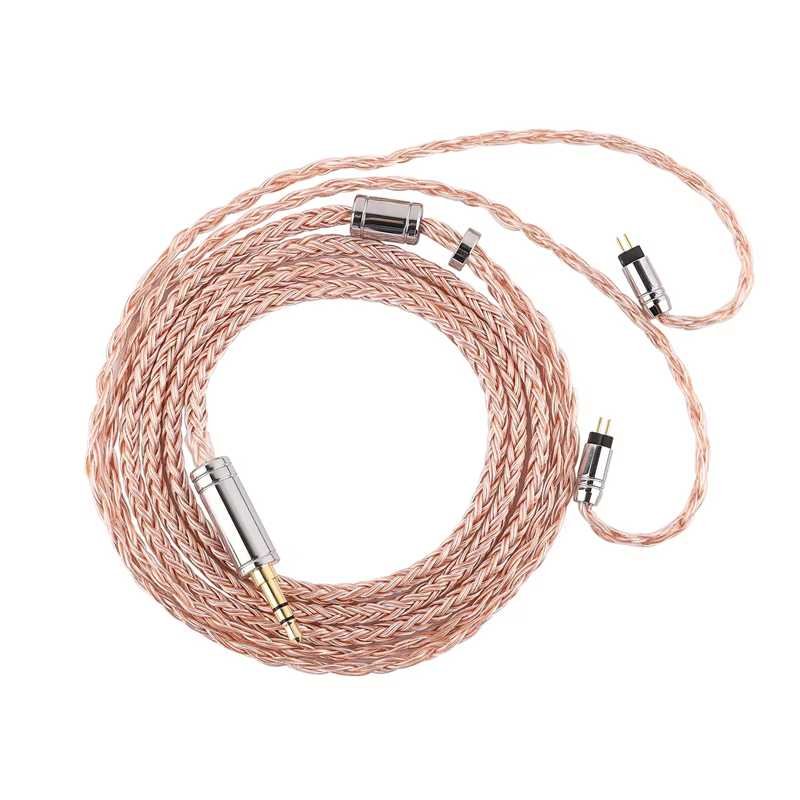
Which conductors are typically used in IEM cables?
Unlike power or data cables, IEM cables carry low-voltage analog audio signals. This changes everything about conductor choice.
Common conductor characteristics include:
- Fine-stranded copper for flexibility
- Small gauge conductors to reduce weight
- Balanced pair layouts for noise rejection (in some designs)
Silver-plated copper may be used in some premium designs, but from an engineering perspective, strand count and geometry matter more than marketing materials.
Too stiff a conductor increases microphonics. Too thin a conductor increases resistance and fragility. The balance is subtle—and often missed by non-specialists.
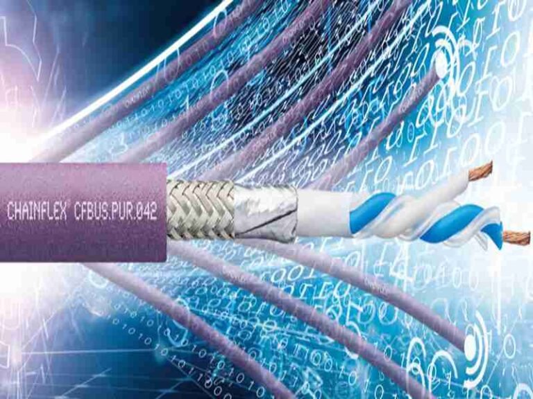
Do DCP IEM cables require shielding or twisting?
Not all IEM cables are shielded, but many DCP-style IEM cables include some form of noise control, such as:
- Twisted pairs to reduce interference
- Spiral or light foil shielding in high-noise environments
- Drain wire grounding through the connector shell
Shielding decisions depend heavily on usage scenario:
| Usage Environment | Typical Structure |
|---|---|
| Stage performance | Twisted conductors, soft jacket |
| Studio monitoring | Optional shielding |
| OEM embedded audio | Shielded or hybrid |
Over-shielding can make cables stiff and uncomfortable. Under-shielding can introduce noise. This is why “DCP” cables are rarely one-size-fits-all.
How flexibility, OD, and jacket materials affect real use
From a user’s perspective, comfort matters as much as sound.
Key mechanical factors include:
- Outer diameter (OD): Smaller OD improves comfort but limits durability
- Jacket material: TPU, TPE, or soft PVC are common
- Memory effect: Poor materials retain bends and cause annoyance
A well-designed DCP IEM cable feels “invisible” during use. That feeling is engineered, not accidental.
Table: Typical Structural Parameters of DCP IEM Cables
| Parameter | Typical Range | Why It Matters |
|---|---|---|
| Conductor gauge | Ultra-fine stranded | Flexibility & comfort |
| Shielding | None / light | Noise vs stiffness |
| Outer diameter | Small | Wearability |
| Jacket material | Soft TPU/TPE | Low microphonics |
| Cable length | Custom | Movement freedom |
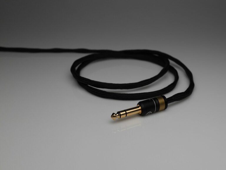
Which Connectors Are Commonly Used on DCP IEM Cables?
DCP IEM cables commonly use small, low-profile audio connectors such as 2-pin (0.78 mm), MMCX, or proprietary IEM connectors, depending on brand and application. Connector choice affects signal stability, durability, user comfort, and long-term reliability, making it a critical design decision in custom IEM cable assemblies.
Why connectors matter more than most buyers expect
In IEM systems, the connector is often the first point of failure, not the cable itself.
Real-world issues typically appear as:
- Audio dropouts when the user moves
- Crackling noise when the connector rotates
- One channel cutting out intermittently
- Premature wear after repeated plugging
These problems are rarely caused by the conductor alone. They are almost always related to connector design, tolerance, and termination quality.
For DCP-style IEM cables—where performance and stability are expected—connector choice is never cosmetic. It directly affects signal integrity and user experience.
2-Pin IEM connectors — simple, stable, but orientation-sensitive
The 2-pin (commonly 0.78 mm) connector is one of the most widely used IEM interfaces.
Typical characteristics:
- Two parallel pins for left/right signal
- Fixed orientation (polarity matters)
- No rotation once inserted
- Lightweight and compact
Advantages in DCP IEM applications:
- Very stable electrical contact
- Low risk of micro-movement noise
- Easy to control pinout consistency
- Preferred for stage monitoring where movement is frequent
Limitations:
- Pins can bend if misaligned
- Wear depends heavily on insertion force control
- Less forgiving during frequent swapping
For many professional users, 2-pin connectors are favored precisely because they do not rotate, reducing unpredictable noise during performance.

MMCX connectors — rotational freedom with trade-offs
MMCX connectors are also common in IEM cables, especially in consumer and semi-professional products.
Key features:
- Coaxial snap-on structure
- 360-degree rotation
- Compact size
Why some DCP IEM cables use MMCX:
- Easier user handling
- Reduced cable twist stress
- Cleaner cable routing over the ear
Why others avoid them:
- Rotation can introduce wear-related noise
- Contact resistance may change over time
- Quality varies significantly between suppliers
In controlled studio environments, MMCX can work well. In high-movement stage use, rotation-induced noise is a real concern unless connector quality is tightly controlled.

Proprietary or brand-specific connectors
Some IEM brands use custom connector geometries to control ecosystem compatibility or improve mechanical fit.
From a manufacturing perspective, these projects usually start with:
- Customer-provided samples or photos
- Partial drawings or pin descriptions
- Requests like “same structure, different length”
This is where DCP IEM cable projects frequently require reverse engineering, connector sourcing decisions (original vs compatible), and drawing confirmation before production.
Table: Common IEM Connector Types in DCP Cable Projects
| Connector Type | Stability | Flexibility | Typical Use |
|---|---|---|---|
| 2-Pin (0.78 mm) | High | Medium | Stage, pro monitoring |
| MMCX | Medium | High | Studio, consumer |
| Proprietary | Project-specific | Project-specific | OEM / brand designs |
Where Are DCP IEM Cables Used in Real Applications?
DCP IEM cables are commonly used in professional stage monitoring, studio recording, broadcast environments, OEM audio devices, and custom audio systems where low noise, flexibility, and reliability are critical. Their usage extends beyond music performance into engineering, medical audio monitoring, and embedded audio products.
Stage monitoring — movement, sweat, and reliability
Live performance is one of the harshest environments for IEM cables.
Real conditions include:
- Constant body movement
- Cable rubbing against clothing
- Moisture from sweat
- Frequent plugging and unplugging
In these environments, the key priorities are:
- Low microphonic noise
- Secure connector retention
- High flex life
- Consistent channel balance
This is why many stage professionals insist on specific cable structures, even if they cannot describe them technically. The “DCP cable” label often comes from experience: “This version doesn’t crackle when I move.”
Studio and broadcast environments — stability over time
In studios and broadcast rooms, cables may not move as much—but they are expected to perform consistently for years.
Typical requirements include:
- Clean analog signal transmission
- Minimal channel imbalance
- Stable impedance characteristics
- Predictable replacement behavior
In these cases, DCP-style IEM cables may emphasize:
- Controlled conductor geometry
- Optional shielding
- Repeatable assembly process
The goal is not flexibility alone, but repeatability across units.
OEM and embedded audio systems
Not all IEM cables are worn by performers.
Many OEM projects use IEM-style cables in:
- Communication headsets
- Diagnostic or monitoring devices
- Training systems
- Industrial audio interfaces
Here, “DCP IEM cable” often means:
- Small OD cable
- Custom length
- Defined pinout
- Controlled noise behavior inside equipment
These customers often approach with drawings or system-level requirements, not audio marketing terms.
Why many customers start with photos instead of specs
In real sourcing scenarios, it is extremely common for customers to provide:
- A photo of an existing cable
- A short description (“low noise”, “soft”, “same as before”)
- No electrical data at all
This is not negligence—it reflects how audio products are actually sourced.
For manufacturers, the challenge is to translate visual and functional expectations into:
- Defined conductor structure
- Connector selection
- Material choices
- Documented drawings
This translation step is where experienced cable assembly suppliers add the most value.
Table: Application vs Design Focus for DCP IEM Cables
| Application | Primary Concern | Typical Design Focus |
|---|---|---|
| Live stage | Noise during movement | Flexibility, stable connectors |
| Studio | Signal consistency | Controlled structure |
| Broadcast | Long-term reliability | Repeatable assembly |
| OEM devices | Fit & documentation | Custom length & pinout |
| Embedded systems | EMI & space | Compact OD, shielding |
Why DCP IEM cables are rarely “standard products”
Across all these applications, one pattern repeats:
The cable that works perfectly in one scenario may fail quietly in another.
This is why most DCP IEM cables are:
- Built to order
- Documented with drawings
- Approved before production
- Reproduced consistently afterward
They are not shelf items. They are solutions.
How Are DCP IEM Cables Designed and Customized in Real Projects?
In real projects, DCP IEM cables are almost never designed from a complete specification. Most designs start with incomplete information—such as a photo, a sample cable, or a short description like “this one is quieter” or “this version lasts longer.” Successful customization depends on how well those fragments are translated into clear structure, defined parameters, and repeatable drawings, not on marketing terms or assumptions.
Below is how DCP IEM cables are actually designed and customized in real-world manufacturing workflows.
How DCP IEM Cable Projects Usually Start (and Why This Is Normal)
Most customers do not come with a full technical brief.
Typical starting inputs include:
- A photo of an existing IEM cable
- A connector type (2-pin, MMCX, or proprietary)
- A cable length request
- A functional comment (“low noise”, “soft”, “for stage use”)
What is usually missing:
- Conductor structure
- Shielding approach
- Jacket material specification
- Mechanical limits (bend radius, flex life)
- Pinout documentation
This is normal in IEM projects because users evaluate cables by behavior, not by datasheets. The role of the manufacturer is to convert usage experience into engineering decisions.
Step 1: Clarifying How the Cable Is Actually Used
Before choosing materials or connectors, engineers first clarify real usage conditions, not theoretical ones.
Key questions usually include:
- Is the cable worn on the body or fixed in a device?
- How much movement happens during use?
- Is cable noise (microphonics) a complaint?
- Is the environment dry, sweaty, or enclosed?
- How often is the cable plugged and unplugged?
These answers directly influence design choices.
For example, a cable designed for stage monitoring will prioritize flexibility and low microphonics, while a cable for an OEM audio device may prioritize stability and documentation.
| Usage Scenario | Design Priority |
|---|---|
| Live stage | Flexibility, low movement noise |
| Studio | Signal consistency |
| Broadcast | Long-term reliability |
| OEM / embedded | Fit, pinout, documentation |
Skipping this step often leads to cables that look correct but fail in real use.
Step 2: Selecting the Conductor Structure
For DCP IEM cables, conductor choice is not about power or bandwidth—it is about mechanical behavior and stability.
Typical conductor decisions include:
- Fine-stranded vs ultra-fine stranded copper
- Strand count vs strand diameter
- Single-core vs paired conductors
- Internal layout to control shape and noise
Too stiff → increased cable noise during movement
Too soft → reduced durability and fatigue life
The goal is balance, not extremes.
| Conductor Choice | Practical Impact |
|---|---|
| Ultra-fine stranded | Higher flexibility, lower microphonics |
| Thicker strands | Better durability, more stiffness |
| Paired layout | Improved noise consistency |
| Loose structure | Comfort, less shape memory |
This is why two IEM cables with the same connector can feel and behave completely differently.
Step 3: Deciding Whether Shielding Is Needed
A common misconception is that all DCP IEM cables must be shielded.
In reality, many IEM cables are intentionally unshielded to improve comfort and reduce movement noise.
Shielding is usually considered only when:
- The cable runs near power electronics
- The environment has strong EMI
- The cable is used inside equipment
- Noise problems cannot be solved structurally
Shielding is often avoided when:
- Flexibility is the top priority
- The cable is worn for long periods
- Microphonics are the main complaint
- Cable length is short
| Scenario | Typical Choice |
|---|---|
| Stage IEM | No shield or very light structure |
| Studio | Optional light shielding |
| Embedded audio | Shielded |
| OEM system | Case-dependent |
Over-shielding often makes IEM cables worse, not better.
Step 4: Connector Selection and Termination Control
Connector choice affects far more than compatibility.
In DCP IEM cables, connectors are a common failure point due to:
- Movement during use
- Repeated insertion cycles
- Contact wear
- Poor termination consistency
Most projects involve one of three connector paths:
| Connector Type | Why It’s Chosen | Risk |
|---|---|---|
| 2-pin (0.78 mm) | Stable, no rotation | Pin damage if misused |
| MMCX | Rotational freedom | Wear-related noise |
| Proprietary | Brand fit | Sourcing & validation |
Equally important is how the connector is terminated.
Even a high-quality connector will fail if soldering, strain relief, or polarity control is poor.
Step 5: Defining Pinout and Channel Consistency
One of the most common IEM cable issues is incorrect channel mapping.
This happens when:
- Only photos are provided
- Polarity is assumed
- Left/right definition is unclear
- No drawing is approved
In DCP IEM projects, pinout confirmation always includes:
- End-to-end signal mapping
- Left/right channel identification
- Connector orientation
- Polarity check
Incorrect pinout does not always cause silence—it often causes subtle phase or balance issues that users describe vaguely as “sounds wrong.”
Step 6: Mechanical Details That Determine Cable Lifespan
Most IEM cable failures are mechanical, not electrical.
Critical mechanical parameters include:
- Cable length tolerance
- Outer diameter (OD)
- Minimum bend radius
- Strain relief design
- Cable exit angle from connectors
A cable that sounds good but fails after months of use is not acceptable in professional environments.
| Mechanical Parameter | Why It Matters |
|---|---|
| OD | Comfort and routing |
| Bend radius | Prevents conductor fatigue |
| Strain relief | Connector longevity |
| Length tolerance | Movement freedom |
These details are often invisible in photos but decisive in real use.
Step 7: Drawings and Pre-Production Approval
In professional DCP IEM cable projects, drawings are not optional.
A proper assembly drawing defines:
- Connector type and orientation
- Pinout
- Cable structure
- Length and tolerance
- Assembly notes

Production should never start without drawing approval.
| Document | Purpose |
|---|---|
| Connector datasheet | Interface definition |
| Cable spec | Material & structure |
| Assembly drawing | Prevent misinterpretation |
| Approved PDF | Production baseline |
This step prevents disputes, rework, and inconsistent future batches.
What Is Typically Customized in DCP IEM Cable Projects
Most customization focuses on fit, reliability, and repeatability, not exotic features.
| Custom Item | Reason |
|---|---|
| Cable length | Comfort and movement |
| Conductor structure | Noise control |
| Shielding | EMI vs flexibility |
| Connector type | Stability and cost |
| Pinout | Channel accuracy |
| Strain relief | Service life |
None of these choices are visible in a product name—but all of them define performance.
What “Well-Designed” Means for a DCP IEM Cable
A well-designed DCP IEM cable:
- Does not introduce noise during movement
- Feels comfortable during long wear
- Maintains channel stability
- Survives real usage conditions
- Can be reproduced consistently
Design success is measured in use, not on paper.
How Engineers, OEMs, and Traders Approach Decisions Differently
Different buyer types evaluate DCP IEM cables differently:
- Engineers focus on structure, repeatability, and risk
- OEM factories prioritize cost, lead time, and consistency
- Traders often work from model numbers or photos and need guidance
A capable supplier adapts communication style and documentation depth to match the buyer—not the other way around.
Final Thoughts: What a “Good” DCP IEM Cable Really Means
A good DCP IEM cable is not defined by hype or materials.
It is defined by whether it:
- Behaves consistently during use
- Minimizes noise during movement
- Fits the user and the device correctly
- Can be reproduced reliably in future orders
- Solves a real problem without introducing new ones
Most DCP IEM cable projects are not about innovation—they are about execution.
That execution depends on experience, communication, and controlled manufacturing.
Sino-Conn supports DCP IEM cable projects by:
- Translating incomplete inputs into clear designs
- Providing fast drawings and technical feedback
- Supporting both prototypes and volume production
- Balancing performance, cost, and lead time realistically
If you are dealing with unclear specs, recurring cable issues, or a need for reliable reproduction, the fastest path forward is usually a technical discussion—not another guess.