Skip to content
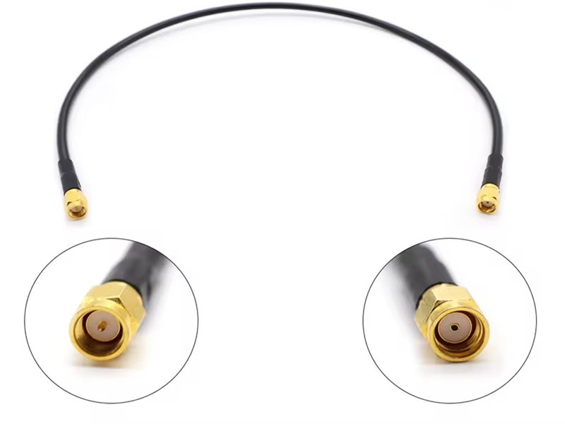
When RF systems fail, the root cause is rarely obvious. Engineers often suspect firmware bugs, unstable power supplies, or noisy active components. Only after days—or weeks—of troubleshooting does attention turn to the cable. By then, the cost is already high. In high-frequency systems, the cable is not a passive link. It is an active RF transmission element that directly affects signal integrity, stability, and repeatability.
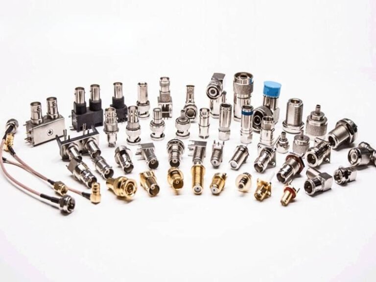
SMA coaxial cables are used everywhere modern RF signals exist: wireless communication modules, medical imaging equipment, test and measurement instruments, industrial RF sensing, and embedded antennas. They look simple, compact, and familiar—but their performance depends on far more than appearance. Small mistakes in impedance control, connector transitions, shielding termination, or mechanical routing can quietly degrade an entire system.
Many people search for “what is an SMA coaxial cable” not because they are learning RF theory, but because something is already going wrong. A prototype works in the lab but fails after installation. A system passes initial tests but shows instability in the field. A buyer receives a cable that “looks right” but does not behave correctly. In many cases, the misunderstanding starts with confusing connector types, cable types, and RF requirements.
An SMA coaxial cable is a radio-frequency (RF) cable assembly that uses an SMA connector and a controlled-impedance coaxial cable, typically 50 ohms, to transmit high-frequency signals with low loss and strong EMI shielding. “SMA” defines the RF connector interface, while the coaxial cable defines the transmission line. SMA coaxial cables are widely used in RF communication, medical devices, industrial systems, and test equipment where signal integrity is critical.
Understanding what an SMA coaxial cable truly is—and what it is not—helps engineers and buyers avoid incorrect assumptions, reduce RF risk, and choose or customize cable assemblies that perform reliably beyond the lab. Let’s start from the fundamentals.
What Is an SMA Coaxial Cable?

An SMA coaxial cable is a radio-frequency (RF) cable assembly that combines an SMA connector with a controlled-impedance coaxial cable—most commonly 50 ohms—to transmit high-frequency signals with low loss, stable impedance, and strong resistance to electromagnetic interference (EMI). It is not simply a cable with an SMA plug attached, but a precision RF transmission line whose electrical and mechanical characteristics directly affect system performance.
In practical RF systems, an SMA coaxial cable must be treated as an active part of the signal path, not as a passive accessory. Its internal structure, material consistency, and connector transitions determine whether RF energy is delivered cleanly from source to load, or partially lost through reflection, radiation, or attenuation.
To understand what an SMA coaxial cable truly is, it helps to separate the concept into three distinct but interdependent elements: the SMA interface, the coaxial cable structure, and the RF signal requirements.
What Does “SMA” Mean in an SMA Coaxial Cable?
SMA stands for SubMiniature version A, a threaded RF connector interface originally developed for microwave and high-frequency applications. The SMA connector defines the mechanical and electrical interface between the cable and RF equipment, ensuring consistent impedance and stable grounding at the connection point.
Key characteristics of SMA connectors include:
- Threaded coupling for vibration resistance and mechanical stability
- Nominal 50-ohm impedance
- Typical frequency capability up to 18 GHz (higher for precision variants)
- Compact size suitable for dense RF layouts
It is important to note that SMA is a connector standard, not a cable type. The connector alone does not guarantee RF performance; it must be properly matched with an appropriate coaxial cable and assembled using RF-controlled processes.
What Makes the Cable “Coaxial”?
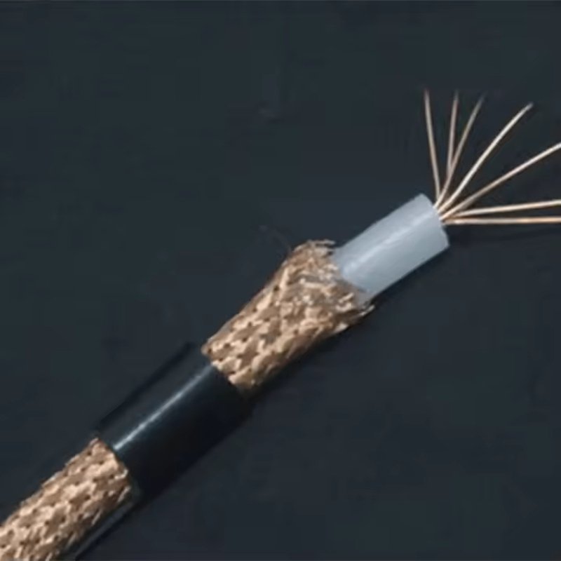
“Coaxial” refers to the concentric physical structure of the cable, where all conductive elements share a common central axis. This geometry is essential for RF transmission because it controls how electromagnetic energy propagates along the cable.
A typical coaxial structure includes:
- A center conductor that carries the RF signal
- A dielectric insulator that defines spacing and characteristic impedance
- A shielding layer (braid, foil, or a combination) that serves as the return path and EMI barrier
- An outer jacket that provides mechanical and environmental protection
This structure confines the electromagnetic field between the center conductor and the shield, minimizing radiation, reducing susceptibility to external noise, and maintaining predictable impedance over the cable length. Without this coaxial geometry, high-frequency signals quickly become unstable and lossy.
What Is the Difference Between SMA, RF Cable, and Coaxial Cable?
This is one of the most common—and most costly—sources of confusion for buyers.
| Term | What It Describes | What It Does Not Mean |
|---|---|---|
| RF | The signal frequency range | Not a physical cable |
| Coaxial | The cable structure | Not automatically RF-rated |
| SMA | The connector interface | Not a cable specification |
| SMA coaxial cable | A complete RF cable assembly | Not interchangeable with any coax |
In short:
- RF describes the type of signal
- Coaxial describes how the cable is built
- SMA describes how the cable connects to equipment
An SMA coaxial cable is only correct when all three are properly matched.
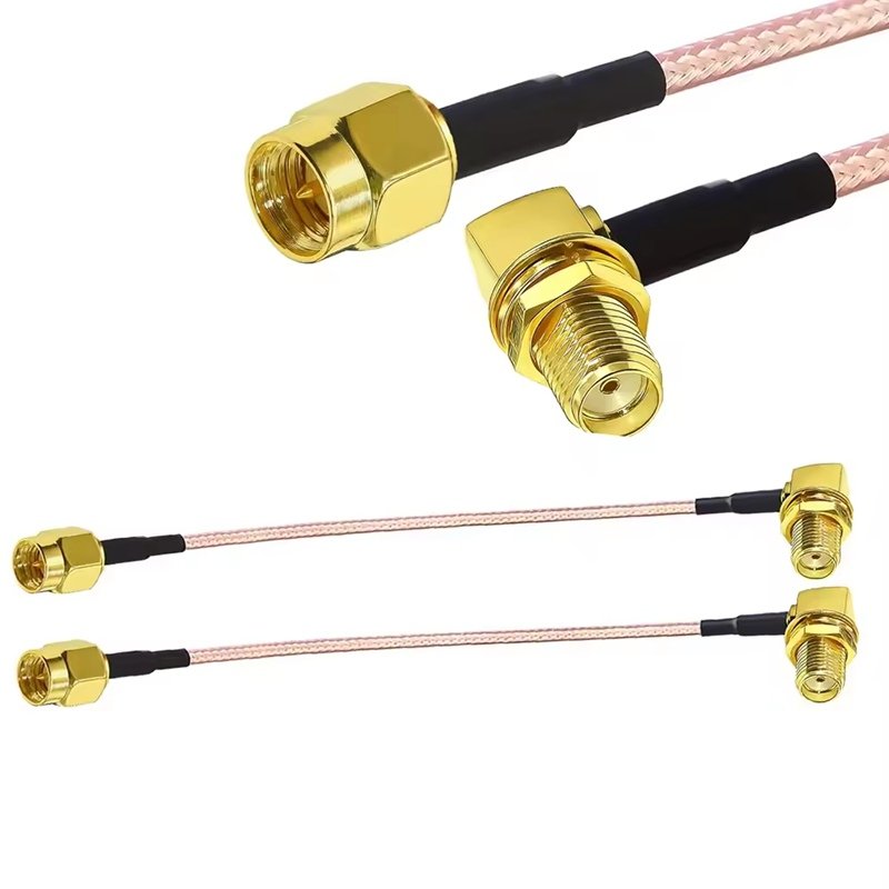
Why SMA Coaxial Cables Are Not Interchangeable
Two SMA coaxial cables may look nearly identical on the outside, yet perform very differently in real RF systems. Differences in dielectric material, impedance tolerance, shielding coverage, or connector termination quality can significantly affect insertion loss, return loss, and long-term stability.
Key factors that differentiate SMA coaxial cables include:
- Impedance accuracy and consistency
- Frequency rating of both cable and connector
- Shield continuity and termination method
- Mechanical stability under bending or vibration
Because of this, SMA coaxial cables should never be selected solely by appearance or connector type. They must be evaluated—and often customized—based on actual electrical, mechanical, and environmental requirements.
How SMA Coaxial Cables Function in Real Systems
In RF applications such as wireless communication, medical imaging, industrial sensing, and test instrumentation, the cable is effectively part of the RF circuit. Even a short SMA coaxial cable can limit system performance if it introduces impedance discontinuities or excessive loss.
For this reason, experienced engineers treat SMA coaxial cables as engineered RF components, not consumables. Correct definition, controlled assembly, and proper validation are essential to ensure that what works in the lab continues to work in real-world deployment.
In summary, an SMA coaxial cable is a precision RF transmission assembly defined by the SMA connector interface, the coaxial cable structure, and the RF performance requirements of the system. Understanding this distinction helps OEMs, engineers, and buyers avoid incorrect assumptions, reduce RF risk, and make better decisions when selecting or customizing RF cable assemblies.
How Does an SMA Coaxial Cable Work?
An SMA coaxial cable works by guiding RF signals through a controlled-impedance coaxial structure while maintaining impedance continuity at the SMA connector interface. The center conductor and shield form a transmission line that confines electromagnetic energy, minimizing reflections, loss, and external interference.
How RF Signals Travel Through an SMA Coaxial Structure
At RF frequencies, signals propagate as electromagnetic waves. The spacing between the conductor and shield—defined by the dielectric—sets the characteristic impedance. Any disruption changes how energy flows.
In an SMA coaxial cable, the connector, cable, and termination must behave as one continuous transmission line. This is why RF cables cannot be treated as simple wiring.
How SMA Connectors Help Maintain Signal Integrity
Threaded SMA connectors provide:
- Stable mechanical contact
- Consistent impedance transition
- Reliable shield continuity
Poor connector assembly can undo even the best cable design.
Which Specifications Matter Most for SMA Coaxial Cables?
In RF systems, performance issues are rarely caused by a single dramatic error. Much more often, they originate from small specification gaps—an impedance tolerance that was never confirmed, a bend radius that looked acceptable on paper, or a connector transition that was assumed rather than defined. For SMA coaxial cables, these details matter because the cable is part of the RF transmission line itself.
An SMA coaxial cable must be specified as a system, not as a connector plus a piece of wire. Electrical performance, mechanical behavior, shielding effectiveness, and connector transitions are tightly linked. Ignoring any one of them can quietly degrade signal integrity, stability, and long-term reliability.
Below are the specification categories that matter most when selecting or customizing an SMA coaxial cable assembly.
Electrical Specifications: The Foundation of RF Performance
Electrical parameters determine whether an SMA coaxial cable can carry RF signals without reflection, distortion, or excessive loss. Among these, impedance is the most critical.
Key electrical specifications include:
- Characteristic impedance (typically 50 Ω for SMA systems)
- Impedance tolerance (often ±1 Ω or tighter in sensitive applications)
- Frequency range the cable and connector are rated to support
- Insertion loss (attenuation) per unit length
- Return loss / VSWR limits
At RF frequencies, even small impedance deviations create reflections that reduce usable signal power and increase noise. These effects accumulate over cable length and across connector transitions, and they are often misdiagnosed as issues with active electronics.
| Electrical Parameter | Why It Matters |
|---|---|
| Impedance value | Prevents mismatch and reflections |
| Impedance tolerance | Ensures repeatability between cables |
| Frequency rating | Defines usable RF bandwidth |
| Insertion loss | Limits system margin |
| VSWR / return loss | Indicates transmission efficiency |
A cable that is “close enough” electrically at low frequency may be completely unsuitable for SMA-based RF systems.
Mechanical Specifications: When Physical Design Affects RF Stability
Mechanical behavior directly influences RF performance over time. SMA coaxial cables rely on precise geometry between the center conductor and the shield. Any deformation changes impedance.
Critical mechanical specifications include:
- Outer diameter (OD) and allowable tolerance
- Minimum bend radius (static and dynamic)
- Flex life under repeated movement
- Strain relief effectiveness near the SMA connector
Excessive bending, pulling, or compression alters the dielectric spacing inside the cable. This may not cause immediate failure, but it often leads to gradual RF drift, increased loss, or intermittent behavior in the field.
| Mechanical Parameter | RF Impact |
|---|---|
| OD tolerance | Affects impedance consistency |
| Bend radius | Prevents dielectric deformation |
| Flex life | Maintains long-term RF stability |
| Strain relief | Protects connector transitions |
In medical, industrial, and test equipment applications, mechanical stress is often the dominant long-term risk, not initial electrical design.
Shielding Effectiveness: Controlling EMI and Signal Leakage
Shielding in SMA coaxial cables serves two functions: it prevents external EMI from entering the signal path, and it prevents RF energy from radiating outward.

Important shielding-related specifications include:
- Shield type (braid, foil, or combined)
- Shield coverage percentage
- Shield continuity along the cable and through the connector
- Shield termination method at the SMA interface
Poor shielding does not always produce obvious failures. Instead, it often causes inconsistent behavior that appears only under certain conditions—near motors, wireless devices, or changing grounding environments.
| Shielding Aspect | Risk if Not Defined |
|---|---|
| Coverage percentage | EMI susceptibility |
| Termination method | Signal leakage and radiation |
| Continuity | Noise instability |
| Ground reference | Ground loop or antenna effects |
In RF systems, shielding must be treated as part of the signal path, not as optional protection.
Connector Interface and Transition Specifications
The transition between the coaxial cable and the SMA connector is one of the highest-risk points in the entire RF signal chain. Even a well-specified cable can underperform if the connector interface introduces impedance discontinuities.
Key interface specifications include:
- SMA connector type and frequency rating
- Center conductor attachment method
- Shield termination style (360° termination vs partial)
- Dimensional control at the mating interface
Connector assembly quality often determines whether a cable performs consistently across production batches.
Environmental and Material Specifications
Real-world environments differ significantly from lab conditions. Environmental specifications define whether RF performance remains stable over time.
Common considerations include:
- Operating temperature range
- Resistance to oils, chemicals, or cleaning agents
- UV and aging resistance
- Halogen-free or low-smoke material requirements
Environmental stress accelerates mechanical and dielectric changes, which eventually appear as RF degradation.
Specification Trade-Offs: Why “More” Is Not Always Better
It is tempting to over-specify every parameter “just in case.” In practice, SMA coaxial cable design involves trade-offs:
- Smaller OD improves routing but increases loss
- Higher shielding improves EMI control but reduces flexibility
- Tighter impedance tolerance improves RF performance but increases manufacturing difficulty
Effective specifications balance actual application needs, not theoretical extremes.
Summary: Core Specifications That Define SMA Coaxial Cable Performance
| Specification Category | Primary Purpose |
|---|---|
| Electrical (impedance, loss) | Signal integrity |
| Mechanical (OD, bend radius) | Stability over time |
| Shielding | EMI control |
| Connector interface | Minimize transitions |
| Environmental | Long-term reliability |
The specifications that matter most for SMA coaxial cables are those that preserve RF performance under real operating conditions, not just during initial testing. Electrical accuracy, mechanical stability, shielding continuity, and connector transition control must work together as a system.
For OEMs and engineers, clearly defining these parameters early—and validating them through drawings, samples, and controlled assembly—is the most effective way to reduce RF risk, avoid redesigns, and ensure consistent performance from prototype to production.
What Is an SMA Coaxial Cable Used For?
SMA coaxial cables are used in RF communication systems, medical imaging devices, test and measurement equipment, industrial RF sensors, and embedded antenna connections where stable high-frequency signal transmission is required.
Why SMA Is Chosen in Medical and Industrial Systems
Threaded coupling resists vibration. Size supports compact layouts. RF performance supports sensitive signals. These factors make SMA common in medical imaging, diagnostics, and industrial RF control.
How Do You Choose or Customize an SMA Coaxial Cable Assembly?
Choosing or customizing an SMA coaxial cable requires defining frequency range, impedance, length, routing, connector type, and environment, then validating the design through drawings and samples before production.
What Information Manufacturers Actually Need
- Application description
- Frequency range
- Cable length & routing
- Connector preference
- Environmental exposure
Photo-only inquiries are common—but they require engineering clarification.
Why Work with a Professional SMA Coaxial Cable Manufacturer?
Professional manufacturers provide engineering support, controlled RF assembly, documentation, and inspection processes that reduce system-level RF risk compared to off-the-shelf cables.
Why Off-the-Shelf SMA Cables Often Fail
Generic cables ignore routing, movement, and environment. Small mismatches accumulate into instability.

Final Thoughts: From Definition to Reliable RF Performance
An SMA coaxial cable is not just an SMA connector plus a piece of coax. It is a precision RF transmission assembly where electrical design, mechanical execution, and manufacturing discipline must align.
At Sino-Conn, we support SMA coaxial cable projects from specification review and drawing confirmation to rapid sampling and volume production. Whether you start with a part number, a drawing, or only a reference photo, our engineering team helps convert requirements into a reliable, manufacturable RF solution.
If you are planning an SMA coaxial cable or custom RF cable assembly project, we welcome you to discuss your application, specifications, and timeline with Sino-Conn—starting from 1 piece, with no MOQ.