Skip to content
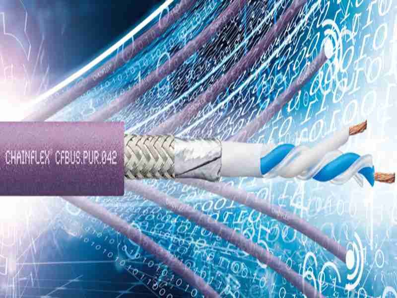
Modern electronic systems are becoming faster, smaller, and more densely packed—but the environments they operate in are often getting harsher. Industrial machines run next to motors and inverters. Medical devices sit beside power supplies and RF modules. Embedded systems are expected to perform reliably inside metal enclosures filled with switching noise. In many of these cases, the weakest point in the system is not the PCB, the processor, or the software—it is the cable connecting everything together.
This is where shielded cables enter the conversation. Many buyers encounter the term “shielded cable” when a system behaves unpredictably: image flicker on a display, unstable sensor readings, communication errors that appear only in the field, or failures that cannot be reproduced in the lab. Shielding is often suggested as a fix—but without a clear understanding of what shielding actually does, when it is necessary, or how it should be implemented, it can quickly become an expensive guess rather than a controlled design decision.
A shielded cable is a cable that includes a conductive shielding layer designed to reduce electromagnetic interference (EMI) affecting signal transmission. Shielded cables are used when electrical noise, high-speed signals, or sensitive data require stable and predictable performance. Proper shielding helps prevent signal distortion, crosstalk, and data errors in industrial, medical, and OEM systems, especially in environments with motors, power electronics, or RF sources.
What makes this topic challenging is that shielding is not binary. Adding a shield does not automatically solve interference problems. In some cases, shielding is unnecessary. In others, the wrong type of shielding—or improper grounding—can make things worse. Understanding shielded cables requires moving beyond definitions and into real usage scenarios.
Let’s start by defining what a shielded cable actually is—and what it is not.
What Is a Shielded Cable?
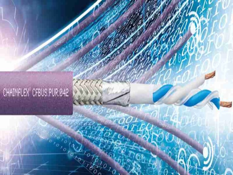
A shielded cable is a cable that incorporates a conductive layer—such as foil, braid, or both—around its conductors to reduce electromagnetic interference. The shield helps protect signals from external noise and prevents the cable itself from emitting interference. Shielded cables are commonly used in industrial, medical, and high-speed signal applications where reliability and signal integrity are critical.
What does “shielded cable” mean in real applications?
In real products, “shielded cable” does not describe a single cable type. It describes a design feature applied to many different cable constructions. A shielded cable may carry power, analog signals, digital data, or high-speed differential pairs—but what they share is a conductive barrier designed to control electromagnetic behavior.
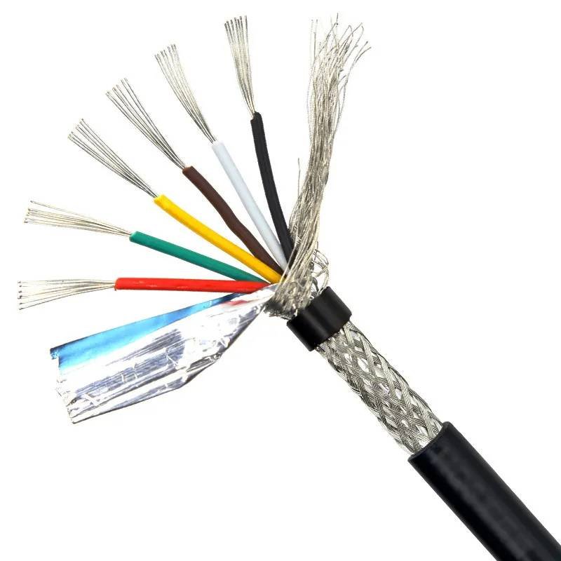
From a manufacturing perspective, shielding is part of the cable structure, not an accessory. It is built into the cable through layers such as aluminum foil, copper braid, spiral wrap, or combinations of these. These layers are carefully selected based on frequency range, mechanical stress, and environmental conditions.
Importantly, shielding is system-dependent. A cable that performs perfectly in one device may fail in another, even with identical electrical specifications, simply because the surrounding electromagnetic environment is different. This is why experienced engineers treat shielding as a system-level decision rather than a checkbox.
What problems does shielding address in signal transmission?
Shielding exists to manage electromagnetic interference (EMI)—both incoming and outgoing. In practice, EMI problems show up as intermittent failures rather than total breakdowns. Signals may degrade only under load, during motor startup, or when nearby equipment is powered on.
Common real-world symptoms include:
- Flickering or unstable video signals
- Random communication dropouts
- Sensor readings that drift or spike
- Errors that appear only after installation
Shielding does not increase signal strength. Instead, it reduces the influence of unwanted energy that couples into the signal path. This distinction matters: shielding is about control and predictability, not amplification.
How Does Cable Shielding Work?
Cable shielding works by using conductive materials to block, absorb, or redirect electromagnetic interference away from signal conductors. The shield creates a controlled path for noise, usually connected to ground, preventing interference from distorting the signal. Effective shielding depends on the shield type, coverage, and proper termination.
How electromagnetic interference affects unshielded cables
Unshielded cables act like antennas. In low-noise environments, this may not matter. But in industrial or medical systems, electromagnetic energy is everywhere: switching power supplies, relays, motors, RF modules, and even nearby cables.
When interference couples into an unshielded conductor, it can:
- Alter voltage thresholds
- Distort timing in digital signals
- Introduce noise into analog measurements
High-speed and low-level signals are especially vulnerable. For example, differential data lines used in LVDS or Ethernet rely on precise voltage differences. External noise can reduce the margin between logic states, causing intermittent errors that are extremely difficult to debug.
How shielding changes signal behavior
Shielding modifies the electromagnetic environment around the conductors. Instead of allowing noise to couple directly into the signal path, the shield intercepts it. Depending on design, the shield may reflect, absorb, or redirect interference toward ground.
However, shielding is only effective when properly grounded. A floating shield can accumulate noise and re-radiate it, sometimes worsening interference. This is why cable termination—how the shield connects to the connector shell or ground plane—is as important as the shield itself.
From a system perspective, shielding provides consistency. It reduces variability caused by installation differences, nearby equipment, or environmental changes. This consistency is often more valuable than raw performance.
Table : Shielded vs Unshielded Cable — Functional Overview
| Feature | Shielded Cable | Unshielded Cable |
|---|---|---|
| EMI resistance | High | Low |
| Signal stability | Consistent | Environment-dependent |
| Cost | Higher | Lower |
| Installation sensitivity | Medium | High |
| Typical use | Industrial, medical | Consumer, low-noise |
What Types of Shielded Cables Are Commonly Used?
The most common shielded cable types include foil-shielded cables, braided-shield cables, and combination foil-plus-braid designs. Each shielding type offers different levels of EMI protection, mechanical durability, and cost. Choosing the correct shielding structure depends on noise environment, signal sensitivity, cable movement, and installation conditions—not just performance specifications.
Foil-Shielded Cables — When compact design matters
Foil shielding uses a thin aluminum or copper foil wrapped around the conductors, usually paired with a drain wire. This structure provides nearly 100% coverage, making it very effective at blocking high-frequency electromagnetic interference.
In real applications, foil shielding is often chosen when:
- Cable routing space is tight
- The cable is installed in a fixed position
- High-frequency noise is present
- Flexing is minimal or none
However, foil shields are mechanically fragile. Repeated bending can cause the foil to crack, reducing effectiveness over time. This is why foil-only shielding is typically used inside enclosures, not in cables exposed to movement or handling.
Engineers often underestimate this tradeoff: excellent EMI performance, but limited mechanical tolerance.
Braided-Shield Cables — When durability is required
Braided shielding is made from woven copper strands surrounding the cable core. Compared to foil, braid provides lower coverage (typically 70–95%), but significantly better mechanical strength.
Braided shields are preferred when:
- Cables experience vibration
- There is repeated plugging and unplugging
- The cable is routed outside the enclosure
- Long-term mechanical reliability matters
From a signal perspective, braided shields are particularly effective against low- to mid-frequency interference, such as noise from motors, relays, and power lines. They are also more forgiving if the cable routing changes slightly during installation.
The tradeoff is size and cost. Braided cables are thicker and usually more expensive than foil-shielded designs.
Foil + Braid Combination — When EMI risk is high
Combination shielding uses both foil and braid layers. This structure provides:
- High-frequency EMI blocking (foil)
- Mechanical durability and low-frequency noise control (braid)
In practice, this is the most common choice for industrial, medical, and high-reliability OEM products, especially when the EMI environment is unknown or difficult to control.
Combination shielding is often selected not because it is always necessary, but because it reduces risk. It gives engineers more margin against installation variation, grounding differences, and future system changes.
The downside is increased diameter and cost—but in regulated or long-lifecycle products, this tradeoff is usually acceptable.

Table : Comparison of Common Shielding Types
| Shield Type | EMI Protection | Mechanical Strength | Typical Use |
|---|---|---|---|
| Foil only | High (HF) | Low | Fixed internal cables |
| Braid only | Medium | High | External or flexible cables |
| Foil + braid | Very high | High | Industrial & medical systems |
| Spiral / special | Application-specific | Medium | Custom designs |
Which Applications Require Shielded Cables?
Shielded cables are required when signal integrity must be maintained in electrically noisy environments or when sensitive data is transmitted. Common applications include industrial automation, medical devices, high-speed data links, and long cable runs near power equipment. Shielding is typically unnecessary in low-noise, short-distance, consumer-level applications.
Industrial environments — where shielding is often mandatory
Industrial equipment is one of the most common reasons customers request shielded cables. The reason is simple: noise is unavoidable.
Typical interference sources include:
- Motors and drives
- Switching power supplies
- High-current cables
- Relays and solenoids
In these environments, unshielded cables may work during testing but fail intermittently in the field. Shielded cables provide predictable behavior across different installations and operating conditions.
This is why shielded control cables, Ethernet cables, LVDS display cables, and sensor cables are standard in automation systems.
Medical devices — where stability outweighs cost
In medical systems, shielding is less about performance optimization and more about risk control.
Medical devices often require:
- Stable image signals
- Clean sensor data
- Repeatable behavior across units
Even minor signal instability can lead to misinterpretation or device malfunction. Once a system is validated and approved, changes are expensive. For this reason, many medical designs default to shielded cables even when unshielded options might work in theory.
Here, shielding acts as insurance against unknown variables.
High-speed and low-level signals
Some signals are inherently sensitive:
- LVDS and V-by-One display links
- High-speed digital data
- Low-voltage analog sensors
As signal speeds increase or voltage levels decrease, noise margins shrink. Shielding helps preserve timing accuracy and voltage integrity, especially over longer cable lengths.
This is one reason why shielded cables are common in embedded systems, even inside closed enclosures.
When shielding may NOT be necessary
Not every cable needs shielding.
Shielding is often unnecessary when:
- Cable length is very short
- Environment is electrically quiet
- Signals are slow and robust
- Cost sensitivity is high
In consumer electronics, unshielded cables are often sufficient and preferred due to lower cost and smaller size. Over-shielding in these cases adds cost without real benefit.
Good design is not about using the most shielding—it is about using the right amount.
Table : Application-Based Shielding Decision Guide
| Application | EMI Risk | Shielding Recommendation |
|---|---|---|
| Industrial automation | High | Foil + braid |
| Medical devices | Medium–high | Foil or combo |
| Consumer electronics | Low | Often unshielded |
| Embedded systems | Medium | Foil or braid |
| Short internal cables | Low | Case-dependent |
What Is the Difference Between Shielded and Unshielded Cable?
The difference between shielded and unshielded cable is not simply whether a metal layer exists. It lies in how electrical noise is managed, how predictable signal behavior is over time, and how much risk a system can tolerate in real operating environments. Choosing between shielded and unshielded cable is a trade-off between noise control, mechanical flexibility, cost, and long-term reliability.
In practice, this decision often determines whether a system works reliably in the field—or only on the test bench.
How Shielded and Unshielded Cables Handle Electrical Noise
The most fundamental difference is how each cable type deals with electromagnetic interference (EMI).
- Unshielded cables rely on conductor spacing, twisting, and signal tolerance to live with noise.
- Shielded cables use conductive layers (foil, braid, or both) to block or redirect noise away from signal conductors.
In a clean electrical environment, both may work equally well. In noisy environments, their behavior diverges quickly.
Typical noise sources include:
- Motors and variable-frequency drives
- Switching power supplies
- High-current power cables
- RF modules and wireless devices
Unshielded cables exposed to these sources often show intermittent issues rather than total failure—making problems harder to diagnose.
What Problems Appear with Unshielded Cables in Noisy Environments
Customers often ask, “If it works now, why add shielding?”
The answer usually appears after installation, not during testing.
Common real-world issues seen with unshielded cables include:
- Display flicker or momentary black screens
- Random data errors or communication dropouts
- Sensor values drifting or spiking
- Failures that occur only when nearby equipment turns on
These problems are usually environment-dependent. Move the same system to a different factory, hospital, or cabinet layout, and behavior changes.
Shielding doesn’t increase signal strength—it reduces environmental sensitivity.
How Shielded Cables Improve Stability (Not Performance)
A common misconception is that shielded cables “improve signal quality.”
In reality, shielding improves signal consistency, not raw performance.
Shielded cables:
- Reduce variability caused by EMI
- Make signal behavior more repeatable across installations
- Increase margin against unknown or changing environments
This predictability is why shielded cables are widely used in:
- Industrial automation
- Medical equipment
- Embedded and OEM systems
- Long-lifecycle products
For these systems, stability is more valuable than maximum bandwidth or flexibility.
Mechanical and Installation Differences That Matter in Practice
Shielding affects more than electrical behavior—it changes how the cable behaves mechanically.
Shielded cables are typically:
- Thicker in outer diameter
- Heavier
- Less flexible than unshielded cables
- More sensitive to bend radius and strain relief
This impacts:
- Routing inside enclosures
- Installation space
- Connector stress over time
In tight or moving applications, an unshielded cable may actually last longer if EMI risk is low. This is why experienced engineers do not default to shielding—they evaluate both electrical and mechanical conditions.
Cost Difference: Unit Price vs System Cost
Another common mistake is comparing shielded and unshielded cables only by unit price.
Shielded cables cost more because:
- Additional conductive materials are used
- Assembly is more complex
- Termination requires more control
- Quality inspection is stricter
However, system-level cost tells a different story.
One field failure caused by EMI can cost:
- More than hundreds of shielded cables
- Downtime, service calls, or recalls
- Engineering time for troubleshooting and redesign
For industrial and medical products, shielding is often chosen as risk insurance, not as a performance upgrade.
When Shielding Can Actually Make Things Worse
More shielding is not always better.
Poorly designed or improperly grounded shields can:
- Act as antennas
- Increase noise instead of reducing it
- Create ground loops
- Cause unpredictable failures
This is why shield termination and grounding strategy matter as much as the shield itself. A shield that is not correctly connected to ground can introduce more problems than an unshielded cable.
Table: Shielded vs Unshielded Cable — Practical Comparison
| Aspect | Shielded Cable | Unshielded Cable |
|---|---|---|
| EMI resistance | High | Low–medium |
| Signal stability | Very consistent | Environment-dependent |
| Cable size | Larger | Smaller |
| Flexibility | Lower | Higher |
| Installation tolerance | Lower | Higher |
| Unit cost | Higher | Lower |
| Best suited for | Noisy or critical systems | Clean, low-risk environments |

How Engineers and Buyers Actually Choose Between Them
In real projects, the decision is usually based on risk tolerance, not theory.
- Engineers choose shielded cables when signal margin is tight or environment is unpredictable.
- OEMs choose shielding when field failure cost outweighs cable cost.
- Procurement teams prefer unshielded cables when environment is proven clean and stable.
The correct choice is rarely emotional—it is contextual.
The Real Difference, Summed Up Simply
- Unshielded cable works well when the environment is clean, space is tight, and cost sensitivity is high.
- Shielded cable is used when stability, predictability, and long-term reliability matter more than flexibility or unit price.
The mistake is not choosing shielded or unshielded.
The mistake is choosing without understanding the environment the cable must survive.
How Are Shielded Cables Designed and Customized in Real Projects?
Shielded cables are rarely designed from a perfect specification. In real projects, customization starts with incomplete information, real-world constraints, and practical trade-offs between EMI control, mechanical fit, cost, and lead time. Successful shielded cable design depends less on theory and more on how noise, installation, and usage conditions are understood and translated into a manufacturable cable structure.
Below is how shielded cable projects are actually designed and customized in practice.
How Shielded Cable Projects Usually Start (and Why That’s Normal)
Most customers do not begin with a full cable specification.
Typical starting points include:
- A photo of an existing cable
- A connector model number
- A description like “signal unstable” or “needs shielding”
- A drawing that only shows connector ends
What is usually missing:
- EMI environment description
- Shield type and coverage
- Grounding method
- Mechanical constraints (bend, space, movement)
This is normal. Shielded cable projects are often problem-driven, not spec-driven. The key is whether the supplier can identify what information matters and what does not.
Step 1: Clarifying the Real Operating Environment
Before choosing any shielding structure, engineers first clarify where and how the cable is used.
Typical questions include:
- Is the cable installed inside or outside equipment?
- Is it static or moving during operation?
- Is it near motors, power supplies, or RF sources?
- What is the operating temperature range?
- Is the enclosure metal or plastic?
These answers often decide whether shielding is necessary at all, and if so, how aggressive it needs to be.
Many “EMI problems” turn out to be routing or grounding issues rather than missing shielding. Skipping this step often leads to over-designed, expensive cables that still fail.
Step 2: Selecting the Shielding Structure Based on Risk, Not Habit
Once the environment is understood, shielding structure is selected based on risk level, not default preference.
Common options include:
- Foil shielding for compact, static, high-frequency noise
- Braided shielding for mechanical durability and low-frequency noise
- Foil + braid for mixed or unknown EMI environments
| Shield Structure | When It’s Typically Chosen | Trade-Off |
|---|---|---|
| Foil only | Tight space, fixed routing | Poor flex life |
| Braid only | Vibration, handling | Larger OD |
| Foil + braid | Industrial / medical | Higher cost |
| Custom / spiral | Special constraints | Design effort |
The goal is not “maximum shielding,” but sufficient margin for real operation.
Step 3: Defining Grounding and Shield Termination
Shielding only works when the shield is terminated correctly.
This is one of the most common failure points.
Key decisions include:
- Single-end or both-end grounding
- 360-degree shell termination vs drain wire
- Connector shell continuity
- Ground reference consistency
A poorly grounded shield can:
- Re-radiate noise
- Create ground loops
- Perform worse than an unshielded cable
In many real projects, adjusting termination solves EMI issues without changing the shield type.
Step 4: Mechanical Design — Length, Routing, and Strain Relief
Mechanical design is often underestimated, but it strongly affects long-term performance.
Typical mechanical parameters that must be defined:
- Cable length and tolerance
- Outer diameter (OD)
- Minimum bend radius
- Static vs dynamic use
- Strain relief structure
A shielded cable that is bent too tightly may experience:
- Shield cracking
- Loss of coverage
- Gradual EMI degradation
| Mechanical Parameter | Why It Matters |
|---|---|
| Length | Prevents excess slack or tension |
| OD | Determines routing feasibility |
| Bend radius | Protects shield integrity |
| Strain relief | Prevents connector failure |
This is why many shielded cables are custom-length, even when signals are standard.
Step 5: Connector Choice — Original vs Compatible
Connector selection affects more than fit.
In shielded cable assemblies, connectors influence:
- Ground continuity
- Shield termination quality
- Mechanical retention
- Cost and lead time
| Connector Option | Advantage | Limitation |
|---|---|---|
| Original brand | Predictable quality | Longer lead time, less flexible |
| Compatible | Fast supply, lower cost | Requires validation |
Functionally, both can work well if the termination and grounding are controlled. The choice is usually driven by project timeline, volume, and budget—not performance alone.
Step 6: Pinout Definition and Internal Structure Control
Pinout errors are a major cause of failures, especially when customers provide only photos or partial drawings.
Design confirmation includes:
- End-to-end pin mapping
- Shield-to-shell connection points
- Pair grouping for differential signals
- Internal structure consistency
These details are always confirmed in drawings, not by assumption.
Verbal confirmation is unreliable. Drawings are not paperwork—they are risk control tools.
Step 7: CAD-to-PDF Drawings and Pre-Production Approval
Before production, a controlled drawing is created showing:
- Connector views and orientation
- Pinout tables
- Shield structure notes
- Length and tolerance
- Strain relief details
The drawing is sent to the customer for approval.
Only after approval does production begin.
This step prevents:
- Specification drift
- Misunderstanding between sales and production
- Disputes during mass production
| Document | Purpose |
|---|---|
| Cable datasheet | Electrical & material reference |
| Connector datasheet | Mechanical definition |
| Assembly drawing | Structure & pinout |
| Approved PDF | Production baseline |
What Is Typically Customized in Shielded Cable Projects
In real projects, customization usually focuses on fit, reliability, and risk reduction, not exotic designs.
| Custom Item | Why Customers Customize It |
|---|---|
| Cable length | Match enclosure routing |
| Shield type | Control EMI risk |
| Connector angle | Ease installation |
| Jacket material | Heat, oil, chemicals |
| Grounding method | Improve shielding effectiveness |
| Documentation | Ensure repeatability |
Almost none of these are visible in a product photo—but all of them affect performance.
Why Shielded Cable Customization Is About Translation, Not Reinvention
Most shielded cable projects are not about inventing new technology.
They are about:
- Translating a noisy environment into a stable cable design
- Turning incomplete information into controlled documentation
- Balancing cost, lead time, and reliability
The fastest projects are not those with the most data—but those with clear communication and fast engineering feedback.
What “Well-Designed” Means for Shielded Cables
A well-designed shielded cable is one that:
- Works reliably across installations
- Tolerates real-world noise
- Fits mechanically without stress
- Can be reproduced consistently
- Does not require field debugging
If a cable meets these criteria, the design is successful—regardless of how complex it looks on paper.
Final Thoughts: Shielded Cable Is a Design Decision, Not a Checkbox
Shielded cables are not inherently better than unshielded ones.
They are tools, chosen for specific problems.
In clean environments, unshielded cables may be the smartest solution.
In noisy or regulated systems, shielding provides stability and risk control.
The mistake is not choosing shielded or unshielded.
The mistake is choosing without understanding why.
Sino-Conn supports shielded cable projects from early concept to production by:
- Helping clarify incomplete requirements
- Providing fast drawings and technical feedback
- Offering flexible connector and material options
- Supporting both prototypes and volume production
If you are dealing with unclear specifications, legacy designs, or EMI-related issues, a technical discussion is often the fastest way to reach a stable solution.