Skip to content
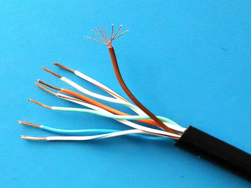
Local Ethernet networks have transformed over the years, but physical cables remain essential—especially in engineering labs, industrial automation systems, and OEM production lines. Among the different types of Ethernet cables, the cross cable (or crossover cable) is one that often causes confusion. Many users recognize the term but are unsure how it works, what makes it different from a straight-through cable, and why certain systems still rely on it despite modern Auto-MDI/MDIX features.
A cross cable is a network cable where the transmit (TX) and receive (RX) wire pairs are swapped to allow two similar devices—such as two computers, two switches, or two PLC controllers—to communicate directly without a switch or hub. One connector uses T568A wiring, while the other uses T568B, enabling the TX pins of one device to reach the RX pins of the other. This cable type is still used in legacy hardware, industrial devices, embedded systems, and controlled testing environments.
If you’ve ever connected two devices directly and found that communication didn’t work, understanding crossover wiring can save significant troubleshooting time. This guide explains what a cross cable is, how it works, where it is still used, and why custom crossover assemblies remain important in industry applications today.
What Is a Cross Cable?
A cross cable (or crossover Ethernet cable) is an Ethernet cable designed so that its TX and RX wire pairs are swapped between the two ends. This enables two similar network devices to communicate directly—without requiring a switch, hub, or router.
The Purpose of a Cross Cable
Ethernet links traditionally relied on fixed TX/RX roles. Similar devices (PC ↔ PC, switch ↔ switch) transmit and receive on the same pins. Without intervention, both devices attempt to transmit on the same lines, making communication impossible.
A crossover cable solves this problem by physically crossing the send and receive pairs so data flows correctly.
How Ethernet Assigns TX and RX Pairs
In Fast Ethernet (10/100 Mbps):
- Pins 1–2 carry TX
- Pins 3–6 carry RX
When two devices of the same type are connected, a straight cable aligns TX to TX and RX to RX—causing link failure.
Crossover wiring swaps these pairs so TX always reaches RX.
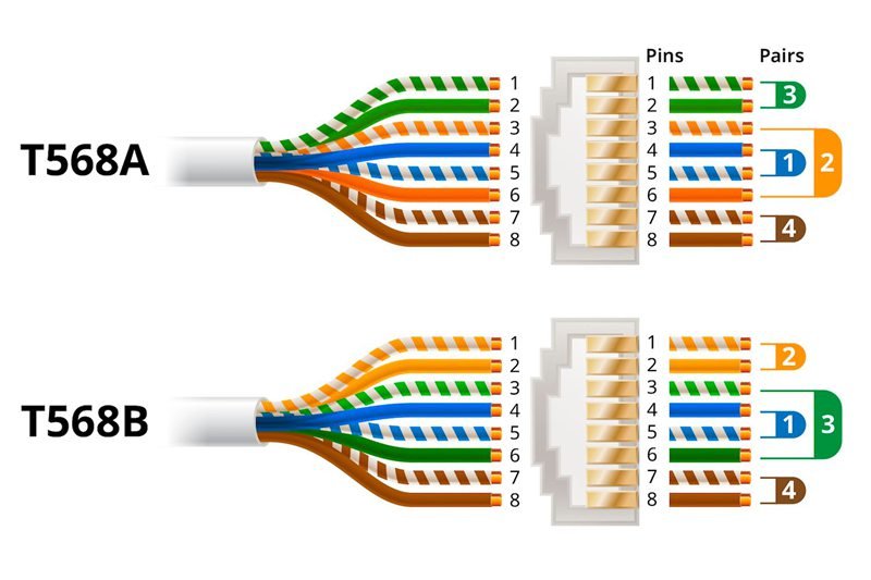
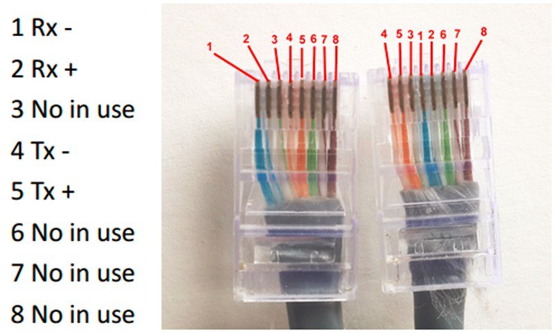
Wiring Map of a Crossover Cable
| Function | T568B Pin (End A) | T568A Pin (End B) | Purpose |
|---|---|---|---|
| TX+ | 1 | 3 | TX → RX |
| TX− | 2 | 6 | TX → RX |
| RX+ | 3 | 1 | RX → TX |
| RX− | 6 | 2 | RX → TX |
Where Cross Cables Are Still Used
Even though modern ports can auto-correct wiring, cross cables remain essential in:
- Industrial PLC, HMI, and CNC systems
- Embedded boards and development kits
- Testing and diagnostics setups
- Legacy PCs, NICs, routers, and switches
- Device-to-device temporary connections
Auto-MDI/MDIX reduces—but does not eliminate—the need for crossover cables.
Quick Comparison (Straight vs. Cross)
| Feature | Straight Cable | Cross Cable |
|---|---|---|
| Wiring | Same at both ends | T568A ↔ T568B |
| TX/RX Swap | No | Yes |
| Device Type | Different devices | Similar devices |
| Typical Use | PC → Switch | PC → PC, Switch → Switch |
How Does a Cross Cable Work?
A cross cable works by reversing the two wire pairs responsible for Ethernet transmitting and receiving. By swapping these specific pairs, the cable ensures each device’s outgoing signals reach the other device’s input pins.
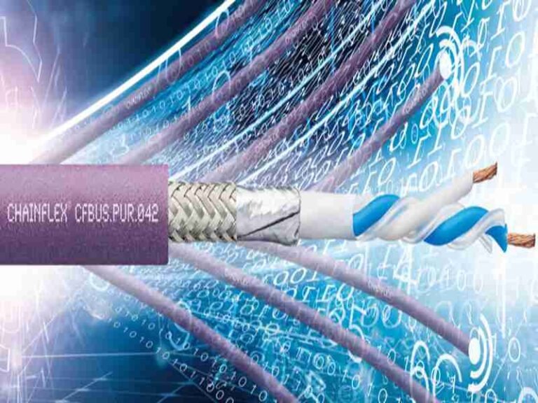
Differential Signaling in Ethernet
Ethernet uses differential pairs designed to reduce EMI and improve signal clarity. These pairs must be correctly aligned for communication to occur.
Straight-through cables send each pin directly to its counterpart.
Crossover cables alter this mapping so TX pairs terminate on RX.
Why Auto-MDI/MDIX Matters
Modern network hardware often includes Auto-MDI/MDIX, which dynamically switches TX/RX roles. However:
- Many industrial PLCs and controllers do not support it
- Low-cost embedded PHY chips often lack the feature
- Auto-negotiation can behave unpredictably during testing
- Some systems require fixed, known TX/RX paths
This makes physical crossover wiring still relevant.
Applies to All Cable Categories
Crossover logic remains the same regardless of:
- Category (Cat5e, Cat6, Cat6A, Cat7)
- Jacket type (PVC, LSZH, TPU, PUR)
- Shielding (UTP, FTP, SFTP)
Only the internal wiring pattern changes.
Which Devices Still Need a Cross Cable?
While modern consumer devices often self-correct signal direction, many professional systems still rely on manual crossover wiring.
1. Legacy Networking Devices
Older network interface cards, routers, and switches do not support Auto-MDI/MDIX. Direct PC-to-PC connections in older systems require a crossover cable.
2. Industrial Automation (PLC, HMI, CNC)
Industrial Ethernet equipment usually prioritizes deterministic behavior over convenience. Many devices maintain fixed TX/RX roles, making crossover connections necessary.
3. Engineering Test Benches
Engineers often prefer predictable wiring:
- Oscilloscope signal capture
- Port validation
- EMC/EMI testing
- Prototype debugging
Auto-switching introduces uncertainty, so fixed crossover wiring is preferred.
4. Embedded Devices & Development Boards
Microcontrollers, small PHY chips, and custom development kits sometimes exclude automatic crossover features to reduce cost.
5. Direct Device-to-Device Networking
Examples include:
- PC ↔ PC
- Switch ↔ Switch (without uplink port)
- Router ↔ Router
- Controller ↔ Controller
Cross cables allow communication without intermediate hardware.
What Is the Difference Between Straight-Through and Cross Cable?
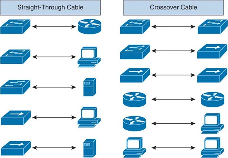
Straight-through and cross cables look identical on the outside but differ internally. Their difference determines whether two devices can communicate directly.
1. Wiring Structure
- Straight cables:
- Both ends follow the same standard (A-A or B-B)
- Crossover cables:
- One end T568A, the other T568B
- TX/RX pairs swapped
2. Device Compatibility
Straight-through cables connect different device types:
- PC → Switch
- Router → Switch
- Server → Patch Panel → Switch
Crossover cables connect similar device types:
- PC ↔ PC
- Switch ↔ Switch
- PLC ↔ PLC
- Test Port ↔ Device Under Test
Comparison Table
| Category | Straight-Through Cable | Cross Cable |
|---|---|---|
| Wiring | Same both ends | A ↔ B swap |
| TX/RX | Not swapped | Swapped |
| Use Case | Different devices | Similar devices |
| Auto-MDI/MDIX | Not required | Helpful but not mandatory |
| Application | Office/network infrastructure | Industrial, legacy, testing |
3. Misunderstandings
- “Cross cables are faster or slower”—False
- “Wrong cable damages equipment”—False
- “Cross cables are obsolete”—Not in industrial or embedded systems
Even Gigabit Ethernet—which uses all four pairs—can still require a crossover if devices lack auto-negotiation.
What Are the Advantages of a Cross Cable?
Crossover cables remain useful for several technical and practical reasons.
1. Direct Device Communication
Allows two devices to communicate without a switch—ideal for:
- Temporary data transfers
- Field maintenance
- Lab connections
2. Predictable Wiring for Testing
Fixed TX/RX mapping ensures repeatable test results, unlike Auto-MDI/MDIX.
3. Compatibility With Legacy Systems
Older equipment often requires manual TX/RX correction.
4. Low Cost and Easy Implementation
The only difference from straight cables is a simple internal pair swap.
5. Essential in Controlled Engineering Environments
When deterministic communication is required, crossover wiring removes uncertainty.
How Do You Identify or Test a Cross Cable?
Crossover cables can be identified visually or with testing tools.
1. Visual Inspection
Check the wire colors at each connector:
- One connector uses T568B (orange pair first)
- The other uses T568A (green pair first)
If the order differs, it is a crossover cable.
2. Cable Testers
Most testers show:
- Pair 1 ↔ Pair 3
- Pair 2 ↔ Pair 6
This indicates crossed pairs.
3. Identifying Samples Without Documentation
In real-world OEM scenarios, buyers often provide:
- Only a cable photo
- A physical sample
- A connector without wiring details
Manufacturers can reverse-engineer the internal mapping before reproducing the cable.
What Is a Custom Cross Cable Assembly?
A custom cross cable assembly is a crossover Ethernet cable built to specific requirements such as:
- Custom pinout
- Length
- Jacket type (PVC, LSZH, TPU, PUR)
- Shielding (UTP/FTP/SFTP)
- Connector types (RJ45, angled RJ45, M12-X)
- Environmental resistance
- Compliance documentation
Why Custom Assemblies Matter
Off-the-shelf crossover cables rarely meet the needs of:
- Industrial machinery
- Outdoor equipment
- Medical devices
- Embedded electronics
- OEM production lines
Engineering constraints—bend radius, EMI, flame ratings, or pinout modifications—often require custom assemblies.
Typical Customization Options
Pinout Definition
Some systems need:
- Modified cross mapping
- Ethernet + auxiliary signals
- Proprietary communication lines
Length and Routing
Custom lengths reduce slack and ensure proper installation.
Shielding and EMI Protection
Industrial applications often require:
- FTP, STP, or SFTP shielding
- 360° grounding
- Noise-resistant construction
Jacket Materials Table
| Material | Properties | Suitable For |
|---|---|---|
| PVC | Flexible, affordable | Indoor office networks |
| LSZH | Low smoke, halogen-free | Hospitals, public buildings |
| TPU/PUR | Abrasion and oil-resistant | Robots, factory floors |
| PE | UV resistant | Outdoor installations |
Connector Configurations
Options include:
- Standard RJ45
- Shielded RJ45
- Right-angle RJ45
- M12-X (industrial)
Documentation
Custom projects often need:
- UL, RoHS, REACH, PFAS-free compliance
- CAD drawings
- Detailed wiring diagrams
- Material specifications
How Much Do Custom Cross Cables Cost?

Pricing varies depending on:
- Cable category (Cat5e–Cat7)
- Shielding level
- Jacket material
- Connector brand (original or compatible)
- Customization complexity
- Order volume
- Certification requirements
Cost Influence Table
| Factor | Effect |
|---|---|
| Category | Higher category = higher cost |
| Shielding | SFTP > FTP > UTP |
| Jacket Material | TPU/PUR > LSZH > PVC |
| Connector Type | Brand-name > compatible |
| Region | US/EU > Japan > Korea > Southeast Asia |
| Industry | Medical/military > industrial > consumer |
| Quantity | High volume lowers cost |
Conclusion
Cross cables may seem like a niche or outdated concept, but they remain critically important in industrial automation, engineering labs, embedded systems, and legacy hardware. Understanding how crossover wiring works—and when it is required—helps prevent communication failures and speeds up troubleshooting.

Custom crossover assemblies, with tailored pinouts, shielding, jacket materials, and compliance certifications, ensure reliable performance in demanding environments. If your equipment, test setup, or OEM system requires precise TX/RX alignment or specific environmental resistance, a custom cross cable is often the safest and most effective solution.