Skip to content
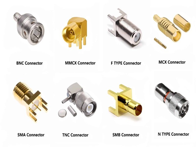
Coaxial cable connectors are found everywhere in modern electronics—from RF antennas and telecom base stations to CCTV systems, medical devices, and test equipment. They serve a deceptively simple purpose: connecting a coaxial cable to another device while preserving signal integrity. Yet behind this simplicity lies a sophisticated combination of electrical engineering, mechanical precision, and material science. As frequencies increase, devices shrink, and environmental demands grow harsher, understanding coaxial connectors becomes increasingly important for engineers, buyers, and system integrators.
A coaxial cable connector is a specialized interface that joins a coaxial cable to equipment or another cable while maintaining controlled impedance, shielding continuity, and low signal loss. These connectors come in many types—such as SMA, BNC, N-type, MMCX, and U.FL—each designed for specific frequency ranges, mechanical constraints, and environmental conditions. Selecting the right connector requires evaluating impedance, frequency, materials, size, durability, and compatibility with the cable’s structure.
The world of coaxial connectors can be confusing because there are dozens of standards, each used for different applications. Engineers may be familiar with SMA or BNC, while consumer electronics users might only know “the TV connector.” Buyers often come with a connector name—or sometimes just a picture—hoping to find a compatible solution. Manufacturers like Sino-Conn often receive a photo of a broken cable and a single question: “Can you make this?” The answer is usually yes, but the reasoning behind that “yes” comes from a deep understanding of connector design, electrical performance, and manufacturability.
Let’s dive deeper into the fundamentals that drive how coaxial connectors work, what types exist, and how to choose the right one for your application.
What Is a Coaxial Cable Connector?
A coaxial cable connector is a mechanical and electrical interface designed to terminate a coaxial cable in a way that preserves its essential characteristics—controlled impedance, shielding continuity, and stable high-frequency signal transmission. Unlike general-purpose connectors, coaxial connectors must maintain the cable’s internal geometry to avoid reflections, insertion loss, and electromagnetic interference (EMI), especially in RF and microwave systems.
Coaxial connectors integrate directly with the layered structure of the cable, ensuring that each component—center conductor, dielectric, shield, and outer jacket—is properly supported and aligned. This precision allows the connector to function as an extension of the cable rather than a weak point in the transmission path.
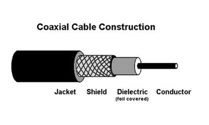
How Coaxial Connectors Match the Structure of the Cable
To maintain stable signal performance, the connector must interface with each layer of a coaxial cable in a highly controlled way. The table below shows how the cable’s structure corresponds to internal connector components:
| Cable Layer | Connector Component | Function |
|---|---|---|
| Center Conductor | Center Pin | Carries RF or high-frequency signals |
| Dielectric Insulation | Internal Insulator | Maintains spacing and defines impedance |
| Shield (Braid / Foil) | Connector Body / Outer Conductor | Provides 360° EMI shielding and continuity |
| Outer Jacket | Housing / Strain Relief | Prevents mechanical stress and protects the termination |
This structural alignment minimizes impedance discontinuities and ensures low-loss transmission across the connector interface. Even slight deviations—such as incorrect pin depth, distorted dielectric, or poorly seated shielding—can cause measurable signal degradation, especially at higher frequencies.
Why Coax Connectors Are Essential in RF and High-Frequency Systems
Coaxial connectors serve not just as physical terminations but as critical electrical components. In RF, telecom, test instrumentation, and data transmission systems, they influence:
- Signal clarity
- VSWR and return loss
- Noise rejection
- System longevity
- Mechanical reliability
Because RF signals are highly sensitive to geometry and impedance variations, the connector often becomes a determining factor in overall system performance.
Where Coaxial Connectors Are Commonly Used
Their combination of shielding, controlled impedance, and mechanical stability allows coaxial connectors to be used across a wide range of industries:
- RF communication equipment (antennas, radios, modules)
- Telecom infrastructure (repeaters, base stations, microwave links)
- Broadcasting and CCTV systems
- Test and measurement instruments
- Medical diagnostic devices
- Automotive radar and sensing
- Consumer electronics (set-top boxes, Wi-Fi devices, televisions)

In each application, the connector must match the cable’s electrical characteristics as well as withstand environmental, mechanical, and durability requirements.
A coaxial cable connector is a precisely engineered component that maintains the cable’s coaxial geometry while providing a stable interface to equipment. By matching every layer of the cable, it ensures low-loss, low-interference transmission. As system frequencies increase and reliability standards tighten, understanding connector behavior becomes fundamental for proper design and selection.
How Does a Coaxial Cable Connector Work?
A coax connector works by maintaining the coaxial structure through the transition point between cable and device. It protects the RF path from reflections, impedance mismatches, and electromagnetic interference (EMI).
A coaxial cable connector works by extending the cable’s coaxial geometry into a mechanically stable interface that preserves impedance and shielding. The connector’s center pin carries the signal, while the outer body maintains shield continuity and provides mechanical coupling. This design ensures low-loss, low-reflection transmission across the operating frequency range.
Internal Structure of a Coaxial Connector
Most connectors include:
- Center pin – carries the signal
- Dielectric support – holds the pin in place and maintains spacing
- Outer conductor / body – continues shielding
- Coupling mechanism (threaded, snap-on, bayonet) – keeps the connection stable
The geometry must be extremely precise. Even a slight deformation can introduce impedance ripple or VSWR changes at high frequencies.
Why Impedance Matching Matters
Common standards:
- 50 ohm – RF communications, Wi-Fi, antennas, test equipment
- 75 ohm – video, broadcasting, CCTV, set-top boxes
Using the wrong impedance can introduce signal reflections and measurable performance loss.
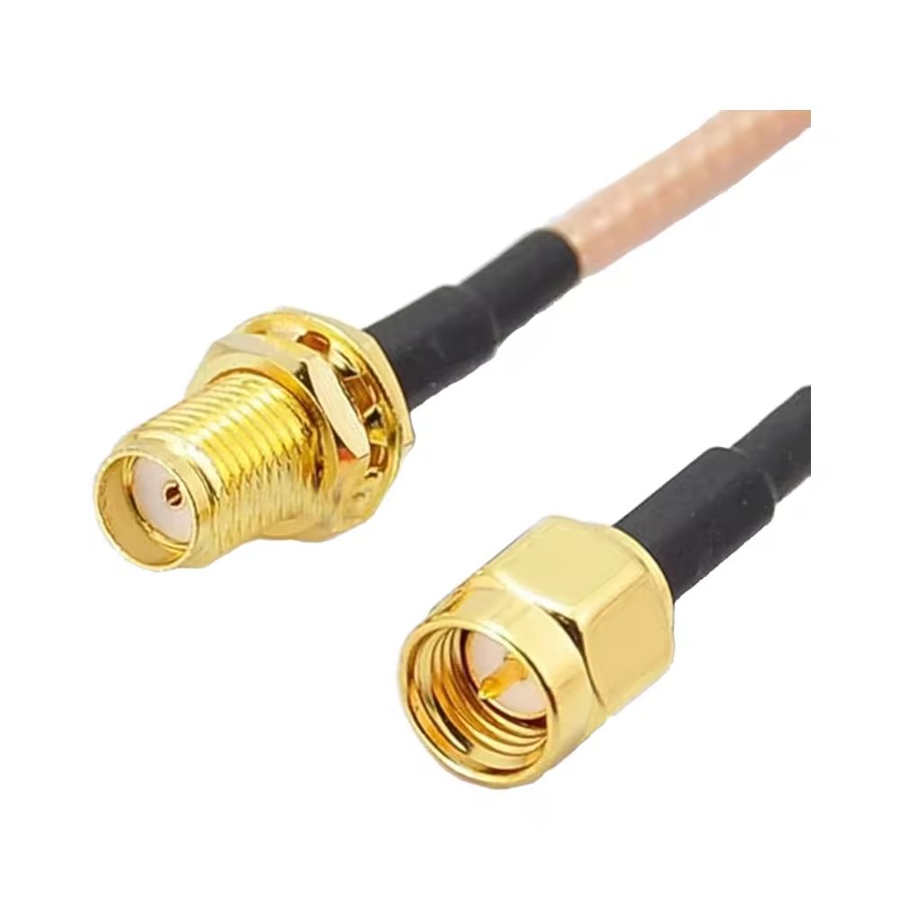
For example:
- A 2.4 GHz Wi-Fi antenna requires a 50-ohm SMA connector.
- A television feed uses a 75-ohm F-type connector.
Shielding and EMI Control
A high-quality connector ensures:
- Reduced RF leakage
- Protection against external interference
- Stable performance in industrial or outdoor environments
Poor shielding results in noise, reduced range, or unstable measurements.
What Are the Common Types of Coaxial Cable Connectors?
Coax connectors vary widely in size, frequency capabilities, durability, and coupling method.
Common coaxial connectors include SMA, SMB, SMC, BNC, TNC, N-type, U.FL, MMCX, and F-type. Each connector serves different frequency ranges and mechanical requirements. SMA and N-type are used for RF and telecom, BNC for labs and video, U.FL/MMCX for compact devices, and F-type for consumer TV. The choice depends on signal frequency, impedance, space constraints, and durability needs.
Overview of Common Coaxial Connector Types
| Connector Type | Impedance | Frequency Range | Typical Applications |
|---|---|---|---|
| SMA | 50Ω | Up to 18 GHz | RF modules, antennas, test equipment |
| BNC | 50Ω / 75Ω | Up to 4 GHz | CCTV, broadcast, labs |
| N-type | 50Ω | Up to 11 GHz | Outdoor RF, telecom infrastructure |
| U.FL | 50Ω | Up to 6 GHz | Wi-Fi modules, compact devices |
| MMCX | 50Ω | Up to 6 GHz | Wearables, IoT devices |
| F-type | 75Ω | Up to 3 GHz | TV, satellite, residential wiring |
In-Depth Analysis of Key Connector Families
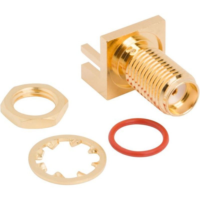
SMA Connectors
Widely used in RF modules, these connectors offer excellent high-frequency performance but require precise torque to avoid damage.
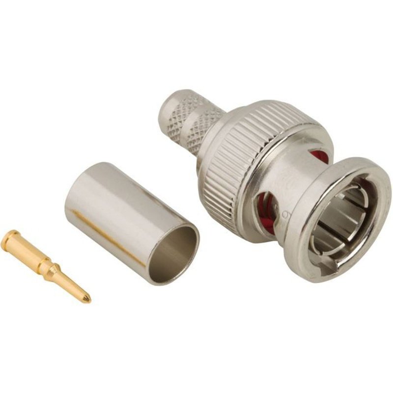
BNC Connectors
Preferred in CCTV and lab environments due to their quick-lock bayonet design.
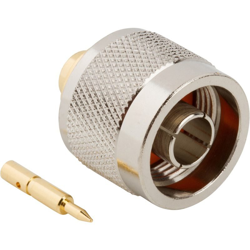
N-Type Connectors
Large, rugged, weather-resistant; ideal for outdoor antennas and telecom towers.
U.FL and MMCX
Micro-connectors designed for compact electronics where space is extremely limited.
What Specifications Do Coaxial Connectors Include?
Datasheets provided by manufacturers like Sino-Conn include detailed parameters beyond simple mechanical drawings.
Coaxial connector specifications include impedance, frequency rating, VSWR, material type, plating, cable compatibility, mechanical tolerances, environmental ratings, and certifications. These parameters ensure the connector matches the cable structure and meets performance, durability, and regulatory requirements.
Typical Specifications Found in Connector Datasheets
| Category | Specifications Included |
|---|---|
| Electrical | Impedance, VSWR, power rating, frequency range |
| Mechanical | Dimensions, torque rating, coupling type |
| Material | Housing metal, plating, dielectric material |
| Environmental | Temperature, flame rating, oil/UV resistance |
| Compliance | UL, ISO, RoHS, REACH, PFAS-free |
| Custom Options | Pinout, overmold, jacket materials, cable OD |
Spec sheets help customers verify connector compatibility with:
- Voltage and current ratings
- Cable outer diameter
- Shielding/EMI requirements
- Environmental resistance
- Halogen-free or PFAS-free requirements
Sino-Conn customers often request datasheets before sampling, and engineers use them to evaluate mechanical tolerance and signal performance.
How to Choose the Right Coaxial Cable Connector?
Choosing the right coaxial cable connector requires evaluating electrical performance, mechanical fit, environmental exposure, and compatibility with the cable and equipment. Because coaxial systems are sensitive to impedance and geometry, the wrong connector can introduce reflection, loss, or mechanical instability. A proper selection process considers impedance (50Ω or 75Ω), frequency handling, connector size, coupling method, durability, and environmental or regulatory requirements.
Selecting an appropriate coaxial connector is not always straightforward, as many connector families appear similar but differ significantly in performance and intended use. The following criteria provide a structured approach for making a technically sound decision.
1. Electrical Requirements
Electrical properties are the foundation of connector performance, especially in RF and high-frequency environments. Key parameters include:
Impedance Matching
Most connectors are designed for:
- 50Ω → RF communication, Wi-Fi, antennas, test instruments
- 75Ω → Video, broadcast, residential TV, CCTV
Using a 50Ω connector on a 75Ω system, or vice versa, may result in:
- Increased VSWR
- Signal reflections
- Reduced transmission range
- Performance variations at higher frequencies
Even if connectors appear mechanically compatible, impedance mismatch alone can compromise system stability.
Frequency Range
Different connector families support different operating frequencies:
- SMA → up to 18 GHz
- N-type → up to ~11 GHz
- BNC → typically ≤ 4 GHz
- U.FL / MMCX → compact, up to 6 GHz
The connector should always exceed the system’s maximum operating frequency to prevent high-frequency attenuation or resonance issues.
VSWR and Return Loss
Low VSWR ensures minimal reflected power. High-performance systems often require:
- VSWR < 1.2:1
- Return loss > 20 dB
These values vary by application but should match system specifications.
2. Mechanical Fit and Design Constraints
Physical compatibility is critical because connectors must align with both the device port and the cable structure.
Connector Size and Form Factor
Consider spatial limitations:
- Compact devices (IoT modules, Wi-Fi cards) → U.FL, MMCX
- Panel-mounted or outdoor systems → N-type, TNC
- Handheld or lab environments → BNC for quick connect/disconnect
Larger connectors generally provide better durability and power handling.
Coupling Mechanism
Different locking methods offer different stability levels:
- Threaded (SMA, N-type): high vibration resistance
- Bayonet (BNC): quick locking
- Snap-on (MMCX, SMB): fast assembly but lower durability
- Push-on micro connectors (U.FL): compact but limited mating cycles
In vibration-heavy or industrial conditions, threaded or bayonet connectors are typically preferred.
Mating Cycles and Durability
Connectors may support:
- 30–50 cycles (U.FL, micro types)
- 500 cycles (SMA)
- 1,000+ cycles (BNC, N-type)
Applications requiring frequent reconnection must consider this parameter.
3. Environmental and Mechanical Stress Conditions
Environmental exposure has a substantial impact on connector longevity and performance.
Temperature Range
Connectors must withstand device operating conditions, especially in:
- Outdoor RF installations
- Automotive radar systems
- Industrial automation
Typical ratings: –40°C to +85°C or higher.
Weatherproofing and IP Rating
Outdoor connectors often require:
- Weather-resistant housings
- O-ring seals
- Corrosion-resistant plating
N-type connectors, for example, are widely used for outdoor antennas due to their robust design.
Vibration, Shock, and Flexing
In high-vibration conditions (vehicles, machinery), threaded connectors are more reliable than snap-on types.
4. Compatibility With Cable Structure
The connector must match the cable’s:
- Outer diameter
- Shielding type (braid, foil, combination)
- Inner conductor size (solid or stranded)
- Dielectric dimensions
Even within the same connector family, versions exist for different cable types (RG174, RG316, RG58, etc.).
A mismatch between connector and cable structure typically leads to:
- Poor crimp/solder joints
- Shield discontinuity
- Impedance variations
- Premature failure under mechanical load
5. Materials, Plating, and Reliability
Connector materials influence:
- Corrosion resistance
- Electrical performance
- Environmental durability
Common materials include:
- Brass with nickel plating → economical, general-purpose
- Stainless steel → high durability, used in test equipment
- Gold plating → improved conductivity, corrosion resistance
Dielectric materials also matter: PTFE is common in high-frequency applications due to its stability.
6. Original vs. Compatible Connector Options
Engineers often choose between:
- Original-brand connectors
- Higher cost
- Longer lead times
- Strict mechanical tolerances
- Required for certain certifications
- Compatible / alternative connectors
- More cost-effective
- Shorter lead times
- Flexible for custom modifications
Both can function properly when manufactured to correct specifications, but the choice depends on budget, project scale, and regulatory constraints.
7. Regulatory and Industry Requirements
Certain applications require specific standards:
- UL → Material safety
- RoHS / REACH → Environmental compliance
- Halogen-free / PFAS-free → Required in medical or eco-focused projects
- Industry-specific testing → Automotive, aerospace, medical
Understanding compliance is important for long-term project sustainability and certification processes.
Summary of This Section
Selecting the right coaxial connector involves evaluating electrical performance, mechanical compatibility, environmental conditions, and regulatory requirements. A careful approach ensures the connector maintains signal integrity, mechanical stability, and long-term reliability. Because coaxial systems are often sensitive to small deviations, connector choice can significantly impact overall system performance.
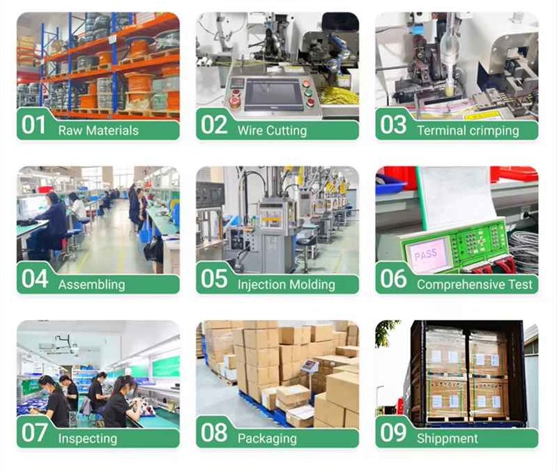
How Are Coaxial Connectors Assembled and Customized?
Coax connector assembly involves precise mechanical and electrical processes to ensure stable performance.
Coaxial connectors are assembled through crimping, soldering, clamping, or overmolding, depending on cable type and application. Customization includes adjusting cable length, materials, pin definitions, shielding, and environmental protection. Drawings and samples are typically required to confirm specifications before production.
Manufacturers like Sino-Conn often receive incomplete information—sometimes only a photo of an old connector—and must reconstruct the assembly through engineering knowledge.
Customizable elements include:
- Cable length
- Pinout definition
- Materials (PVC, TPU, TPE)
- Shielding structure
- Waterproofing level
- Overmold shape
Lead times vary:
- Samples: 2–14 days
- Urgent samples: 2–3 days
- Mass production: 2–4 weeks
These capabilities matter when customers need rapid prototyping or have tight deadlines.
Conclusion:
Coaxial cable connectors, though small, play a critical role in signal integrity, system stability, and long-term reliability. Understanding their types, structu re, and selection criteria helps engineers choose the right connector for high-performance applications.
Sino-Conn supports custom coaxial assemblies with:
- Fast drawings (as fast as 30 minutes)
- Rapid prototyping with no MOQ
- Full customization based on photos, drawings, or specifications
- Strict quality control (in-process + final + pre-shipment)
- Global certifications (UL, ISO, RoHS, REACH, PFAS)
If you need a custom coaxial cable connector or assembly for your project, contact Sino-Conn today to request a quote or discuss your design requirements.