Skip to content
In many discussions about signal transmission, coaxial cable is often treated as a single, generic category. Engineers, buyers, and even some system designers casually refer to “coax” as if all coaxial cables behave the same. In reality, this assumption causes frequent design mistakes, performance mismatches, and long-term reliability issues—especially in systems that carry wide frequency ranges or multiple signal channels simultaneously.
Broadband coaxial cable is one of the most misunderstood variants of coaxial technology. It looks similar to other coaxial cables on the outside, uses familiar materials, and often terminates with common connectors. Yet its design intent, signal behavior, and application logic are fundamentally different from baseband coaxial cables. These differences do not always appear in early testing. Instead, they show up later as signal distortion, unexpected attenuation, poor channel separation, or compatibility problems with modern broadband systems.
Many customers first encounter broadband coaxial cable indirectly—through CATV systems, DOCSIS networks, RF distribution, or hybrid fiber-coax infrastructure. Others encounter it when a project that once worked with simple baseband transmission suddenly needs to support multiple frequencies, higher data rates, or longer distances. At that point, choosing the wrong type of coaxial cable is no longer a minor oversight; it becomes a structural limitation.
Broadband coaxial cable is a type of coaxial cable designed to transmit multiple frequency bands simultaneously over a wide bandwidth. Unlike baseband coaxial cable, which carries a single signal channel, broadband coax supports multi-channel RF transmission and is commonly used in CATV, DOCSIS, RF distribution, and broadband communication systems. Its performance depends on impedance control, shielding, dielectric design, and frequency-specific attenuation characteristics.
Understanding what broadband coaxial cable truly is—and how it differs from other coaxial types—is not just a theoretical exercise. It directly affects system reliability, scalability, and long-term cost. To see why experienced engineers treat broadband coax as a distinct engineering category, we need to start with its definition and underlying principles.
What Is Broadband Coaxial Cable?
Broadband coaxial cable is a coaxial transmission medium designed to carry multiple RF signals across a wide frequency spectrum at the same time. It is optimized for multi-channel communication rather than single-signal transmission. Broadband coaxial cable is widely used in CATV, DOCSIS networks, RF distribution systems, and other applications where high bandwidth, frequency separation, and signal stability are critical.

What Does “Broadband” Mean in Coaxial Transmission?
In coaxial systems, the term broadband does not simply mean “fast” or “high-speed.” It refers to the ability to transmit multiple frequency channels simultaneously, each occupying a defined portion of the frequency spectrum.
Broadband coaxial cable operates as a shared frequency highway. Instead of dedicating the entire cable to a single signal, the available bandwidth is divided into frequency bands. Each band carries a different signal, service, or data stream. This is why broadband coaxial systems are commonly used in environments where television, data, control, and return signals coexist on the same physical cable.
This design philosophy contrasts sharply with baseband transmission, where the entire cable bandwidth is consumed by a single signal at any given time.
How Broadband Coaxial Cable Differs from Standard Coaxial Cable
From the outside, broadband coaxial cable may look identical to other coaxial cables. The difference lies in performance targets rather than appearance.
Broadband coaxial cable is engineered to:
- Maintain stable impedance across a wide frequency range
- Minimize frequency-dependent attenuation
- Preserve channel isolation and signal integrity
- Support long-distance transmission with predictable loss characteristics
Standard coaxial cables that are not designed for broadband use may technically “work” at low frequencies, but their performance degrades as frequency increases or as multiple channels are added. This degradation often appears as subtle signal issues rather than complete failure, making it difficult to diagnose without proper measurement.
How Broadband Coaxial Cable Differs from Baseband Coaxial Cable
This distinction is central to many sourcing and design mistakes.
| Aspect | Baseband Coaxial Cable | Broadband Coaxial Cable |
|---|---|---|
| Signal type | Single channel | Multiple frequency channels |
| Bandwidth usage | Entire cable for one signal | Frequency-divided |
| Typical applications | CCTV, simple data links | CATV, DOCSIS, RF systems |
| Scalability | Limited | High |
| Design focus | Timing & signal shape | Frequency response & isolation |
Baseband coaxial cable is optimized for point-to-point transmission. Broadband coaxial cable is optimized for shared, multi-service transmission. Using one in place of the other often works temporarily—but fails as system complexity increases.
Is Broadband Coaxial Cable an Electrical or RF Transmission Medium?
Broadband coaxial cable sits at the intersection of electrical and RF engineering, but it behaves much more like an RF component than a simple electrical conductor.
Its performance is governed by:
- Characteristic impedance (commonly 75 ohms)
- Dielectric properties across frequency
- Shield effectiveness at high frequencies
- Connector transition behavior
This is why broadband coaxial cable selection cannot rely solely on conductor size or DC resistance. It must be treated as part of a controlled RF transmission system, even in applications that do not feel traditionally “RF” to the end user.
How Does Broadband Coaxial Cable Work?
Broadband coaxial cable works by transmitting multiple RF signals simultaneously through a shared coaxial structure, with each signal occupying a specific frequency band. Controlled impedance, dielectric stability, and shielding ensure that signals remain isolated and stable across the full bandwidth. This allows one cable to carry many services without mutual interference.
How Signal Transmission Works Inside a Coaxial Structure
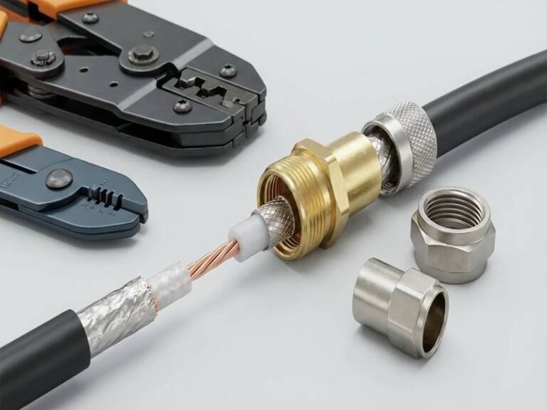
At its core, a coaxial cable consists of:
- A central conductor
- A dielectric insulator
- A conductive shield
- An outer jacket
In broadband operation, signals propagate as electromagnetic waves confined within the dielectric space between the center conductor and the shield. The coaxial geometry ensures that the electromagnetic field remains contained, reducing radiation and susceptibility to external noise.
What makes broadband transmission challenging is not the basic structure, but how that structure behaves across a wide frequency spectrum. Small inconsistencies in materials, geometry, or manufacturing can cause reflections, impedance variation, and frequency-dependent loss.
How Broadband Coaxial Cable Carries Multiple Frequency Channels
Broadband coaxial systems rely on frequency division. Each service or signal is assigned a frequency range, and filters ensure separation at both the transmission and reception ends.
This allows:
- Downstream and upstream signals to coexist
- Multiple services to share one physical medium
- Scalable expansion without replacing infrastructure
However, this only works if the cable maintains consistent performance across all intended frequencies. Poor broadband coaxial cable design leads to uneven attenuation—where some channels perform well and others degrade.
How Baseband and Broadband Coaxial Cables Differ in Signal Transmission
Baseband coaxial cable carries one signal at a time, usually as a digital or analog waveform that occupies the full available bandwidth. Timing, rise time, and waveform integrity are the primary concerns.
Broadband coaxial cable, by contrast, must manage:
- Frequency spacing
- Intermodulation risk
- Channel isolation
- Aggregate noise behavior
A cable optimized for baseband may pass a single high-quality signal perfectly—but fail when asked to carry dozens of channels simultaneously.
Why Impedance Control Matters in Broadband Coaxial Cables
Impedance mismatch is one of the most common causes of broadband performance problems.
In broadband systems:
- Reflections affect specific frequency bands differently
- Small mismatches accumulate over distance
- Connector transitions become critical points
This is why broadband coaxial cable manufacturing focuses heavily on tight impedance tolerance, not just nominal values. A cable labeled “75 ohm” that varies significantly along its length is a liability in broadband systems.
How Shielding Affects Bandwidth and Signal Stability
Shielding in broadband coaxial cable serves two purposes:
- Preventing external interference from entering
- Preventing internal signals from leaking out
As frequency increases, shielding effectiveness becomes more sensitive to braid density, foil continuity, and termination quality. Inadequate shielding may not affect low-frequency channels but can severely impact higher-frequency services—often the ones added later in a system’s life.
What Is Broadband Coaxial Cable Made Of?
Broadband coaxial cable is constructed from a center conductor, dielectric insulation, shielding layers, and an outer jacket, all optimized to maintain stable impedance and low signal loss across a wide frequency range. Material selection and structural consistency are critical to ensure predictable attenuation, channel isolation, and long-term reliability in broadband transmission environments.
Core Structural Layers of a Broadband Coaxial Cable
Although broadband coaxial cables share the same basic architecture as other coaxial cables, each layer is engineered with frequency performance in mind, not just mechanical protection.
| Layer | Primary Function | Why It Matters for Broadband |
|---|---|---|
| Center conductor | Carries RF signal | Surface quality affects high-frequency loss |
| Dielectric | Maintains impedance | Dielectric constant stability controls bandwidth |
| Shielding | EMI containment | Prevents channel leakage & ingress |
| Outer jacket | Environmental protection | Ensures long-term consistency |

The key difference is not what layers exist, but how tightly each layer is controlled during manufacturing.
Center Conductor: Why Surface Quality Matters More Than Size
In broadband coaxial cables, the center conductor may be solid copper, copper-clad steel, or copper-clad aluminum depending on application.
At higher frequencies, signals travel primarily on the surface of the conductor (skin effect). This means:
- Surface smoothness impacts attenuation
- Plating consistency matters more than bulk conductivity
- Minor surface defects can degrade high-frequency channels first
This is why broadband coaxial cables often use precision-drawn conductors with strict surface roughness control, even when DC resistance differences seem negligible on paper.
Dielectric Materials and Broadband Frequency Stability
The dielectric defines the characteristic impedance of the cable. In broadband coaxial cable, impedance must remain stable across a wide frequency spectrum, not just at one test point.
Common dielectric materials include:
| Dielectric Type | Broadband Advantage | Trade-Off |
|---|---|---|
| Solid PE | Cost-effective | Higher loss at high freq |
| Foam PE | Lower attenuation | Sensitive to compression |
| Gas-injected foam | Excellent broadband performance | Higher manufacturing control |
Small variations in dielectric density or concentricity cause frequency-dependent impedance drift, which disproportionately affects broadband systems.
Shielding Design: Why Broadband Needs More Than “Good Enough”
Broadband coaxial cable shielding must prevent:
- External interference entering the cable (ingress)
- Internal signals leaking out (egress)
This is especially critical when multiple channels coexist.
| Shield Type | Typical Use | Broadband Performance |
|---|---|---|
| Single braid | Low-frequency use | Marginal |
| Foil + braid | Most CATV systems | Good |
| Quad-shield | High-density broadband | Excellent |
In broadband systems, poor shielding does not usually cause total signal loss—it causes channel-specific degradation, which is harder to diagnose and more expensive to fix later.
Outer Jacket: Mechanical Stability Supports Electrical Stability
While the outer jacket is not directly involved in signal transmission, it plays a crucial indirect role.
Environmental factors such as:
- UV exposure
- Temperature cycling
- Oil or chemical contact
can alter the physical geometry of the cable over time. Even small deformations change impedance and attenuation characteristics, especially at higher frequencies.
This is why broadband coaxial cable jackets are often selected for dimensional stability, not just abrasion resistance.
Which Specifications Matter Most for Broadband Coaxial Cable?
The most critical specifications for broadband coaxial cable include characteristic impedance, frequency range, attenuation per unit length, shielding effectiveness, and mechanical stability. These parameters directly affect signal quality, scalability, and long-term system reliability. Buyers should evaluate frequency-dependent performance rather than relying on nominal or low-frequency specifications.
Characteristic Impedance: Why 75 Ohms Dominates Broadband
Most broadband coaxial systems use 75-ohm impedance, not by tradition but by physics.
75 ohms offers:
- Lower attenuation per unit length
- Better voltage handling for RF signals
- Optimized balance between loss and power
| Impedance | Typical Use |
|---|---|
| 50 ohms | RF power, antennas |
| 75 ohms | Broadband, CATV, DOCSIS |
Using the wrong impedance may still “work” initially but introduces reflections that accumulate across channels and distance.
Frequency Range vs Usable Bandwidth
Manufacturers often list a maximum frequency rating, but usable bandwidth is more important.
Two cables both rated to 3 GHz may perform very differently across that range.
| Specification | Why It Matters |
|---|---|
| Frequency flatness | Ensures even channel performance |
| Attenuation slope | Predicts high-frequency degradation |
| Group delay | Affects digital modulation |
Broadband systems suffer most when performance is uneven—not when absolute loss is high.
Attenuation: Why “Low Loss” Needs Context
Attenuation is frequency-dependent.
A cable with acceptable loss at 100 MHz may be unusable at 1.5 GHz. This is why broadband coaxial cable attenuation must be evaluated across the entire operating spectrum, not at a single test point.
| Factor Affecting Loss | Impact |
|---|---|
| Conductor roughness | High-frequency loss |
| Dielectric quality | Mid-to-high band stability |
| Shield quality | Noise floor increase |
Shielding Effectiveness and Channel Integrity
Shielding effectiveness is often expressed in dB, but real-world broadband systems care about consistency, not peak values.
Poor shielding leads to:
- Inter-channel interference
- Sensitivity to nearby RF sources
- Regulatory compliance issues
These problems often appear after system expansion, not during initial deployment.
Mechanical Specifications That Quietly Affect RF Performance
Mechanical specs are often treated as secondary, but in broadband coaxial cable they matter.
| Mechanical Parameter | RF Impact |
|---|---|
| Minimum bend radius | Prevents impedance distortion |
| Crush resistance | Maintains dielectric geometry |
| Thermal expansion | Prevents drift over time |
Ignoring these factors leads to gradual performance decay, which is difficult to trace back to the cable.
What Is the Difference Between Baseband and Broadband Coaxial Cable?
Baseband and broadband coaxial cable are built on the same coax structure (center conductor + dielectric + shield), but they’re designed for two different transmission “jobs.”
Baseband coax is typically used to carry one signal stream (one channel) over the cable at a time (common in traditional CCTV and some point-to-point links).
Broadband coax is designed to carry many RF channels at once by splitting the spectrum into frequency bands (common in CATV / DOCSIS / RF distribution).
In real projects, the “wrong choice” usually doesn’t fail instantly—it shows up as higher noise, unstable channels, reduced modem margin, or intermittent issues when the system expands or when frequencies move higher.
How the Signal Uses the Cable: One Channel vs Many Channels
Baseband systems typically “consume” the cable as a single path for one waveform (analog video, or a single digital stream). Broadband systems treat the cable like a frequency highway, where different services occupy different frequency lanes at the same time (downstream, upstream, multiple carriers).
| Item | Baseband Coax | Broadband Coax |
|---|---|---|
| Channel concept | Usually single channel | Multiple channels simultaneously |
| Spectrum usage | Whole cable bandwidth used by one stream | Spectrum divided into bands (FDM) |
| Common systems | Traditional CCTV, simple point-to-point video/data | CATV trunk/drop, DOCSIS/HFC, RF distribution |
| What “breaks” first | Image noise/ghosting, waveform distortion | High-frequency carriers, channel MER/SNR, upstream instability |
Frequency Range in Practice: Where Broadband Becomes “Real Broadband”
A practical way to distinguish them is the frequency plan the system expects.
- Baseband coax use cases often sit in lower or narrower bands (legacy analog video, simple links).
- Broadband coax use cases are built around wideband RF behavior, often from tens of MHz up to 1–3 GHz depending on system.
| Typical Application | Practical Frequency Behavior (Typical) | Coax Type Most Often Used |
|---|---|---|
| Analog CCTV (legacy) | ~DC to a few MHz | Baseband |
| HD-over-coax / multi-service CCTV (varies by technology) | Often tens to hundreds of MHz | Broadband-style performance becomes important |
| CATV / RF distribution | ~50 MHz to 1 GHz+ | Broadband |
| DOCSIS (HFC broadband internet) | Wide spectrum, upstream + downstream bands | Broadband |
Why this matters: coax loss rises with frequency. A cable that looks “fine” at low frequency can be much worse at higher frequency, and broadband systems live in that higher-frequency world.
Attenuation Reality Check: Loss Is Frequency-Dependent (and It Adds Up)
Buyers often compare coax using one generic “low loss” statement. In reality, attenuation changes a lot with frequency and construction.
Below is a typical attenuation trend for common 75Ω RG-6-class coax (actual values vary by conductor, dielectric, shield, and manufacturer):
| Frequency | Typical Attenuation (RG-6 class, per 100 m) | What That Means in the Field |
|---|---|---|
| 50 MHz | ~2–4 dB | Usually forgiving |
| 450 MHz | ~10–15 dB | Mid-band starts to matter |
| 1,000 MHz (1 GHz) | ~18–25 dB | High-band becomes sensitive |
| 2,000 MHz (2 GHz) | ~28–40 dB | Long runs can struggle without design margin |
Rule of thumb:
- In baseband, you usually care about “does the picture/data look clean.”
- In broadband, you care about channel margin across many carriers—high-frequency channels are usually the first to degrade.
Shielding and Noise: The Broadband “Hidden Cost”
Shielding isn’t just about blocking interference—it’s also about keeping signals from leaking out and mixing with neighboring lines (especially in dense bundles, risers, cabinets, or multi-dwelling runs).
| Shield Build | Typical Label | Where It Matters Most |
|---|---|---|
| Foil + braid | Dual shield | Many normal indoor runs |
| Foil + braid + foil | Tri-shield | Noisy environments, denser routing |
| Foil + braid + foil + braid | Quad shield | High RF ingress/egress risk, crowded pathways |
Real-world symptom difference
- Baseband: interference might show as visible noise or image issues.
- Broadband: interference often shows as certain channels dropping, modem errors, reduced throughput, or upstream instability—and can be hard to trace.
Connector and Termination: Why “Works” Isn’t Always “Works Well”
Baseband systems can sometimes tolerate mediocre terminations because they’re not pushing wideband channel performance. Broadband systems are more sensitive to:
- impedance discontinuities at connectors
- braid/foil termination quality
- shielding continuity through the connector body
- micro-bends and tight turns near the connector
| Termination Factor | Baseband Impact | Broadband Impact |
|---|---|---|
| Slight impedance mismatch | Often tolerable | Can create reflections that hurt specific bands |
| Inconsistent shield termination | Sometimes mild | Can raise noise floor / reduce channel MER |
| Tight bend near connector | May still “look ok” | Can shift impedance and worsen high-frequency loss |
Quick Selection Checklist: Which One Do You Actually Need?
Use this practical checklist—no jargon:
Choose “Baseband-style” coax if:
- You carry one signal stream (one camera feed, one point-to-point link)
- Frequency content is relatively low/narrow
- Runs are moderate and environment is not very RF-noisy
Choose “Broadband-grade” coax if:
- You carry multiple services/channels on one line (TV + data, RF distribution)
- You operate in hundreds of MHz to GHz ranges
- You need predictable performance when the system grows (more channels, higher bands)
- Cabling routes are dense, near RF sources, or bundled with other lines
A Simple Buyer Mistake to Avoid
If a supplier or catalog only says “coax cable” (or only says “RG-6”) without showing:
- attenuation vs frequency (a curve or table),
- shielding construction (foil/braid layers),
- impedance tolerance,
- jacket type for environment,
…then you’re not really comparing baseband vs broadband suitability—you’re guessing.
Where Is Broadband Coaxial Cable Used in Real Applications?
Broadband coaxial cable is widely used in systems that transmit multiple RF signals simultaneously across a wide frequency range. Common applications include cable television (CATV), broadband internet infrastructure, satellite distribution, CCTV networks, RF signal distribution, and OEM equipment requiring stable multi-channel RF transmission over distance.
Broadband coaxial cable exists because real-world systems rarely carry just one signal.
Cable Television (CATV) and Hybrid Fiber-Coax (HFC) Networks
The most familiar use of broadband coaxial cable is CATV infrastructure.
In these systems, a single coaxial line may carry:
- Dozens or hundreds of TV channels
- Data streams for broadband internet
- Control and return-path signals
All of these coexist using frequency division, which is only possible when the cable maintains stable impedance and low attenuation across the full operating spectrum.
In HFC networks, fiber handles long-distance transport, while broadband coaxial cable distributes signals locally—making coaxial performance critical to last-mile quality.
Broadband Internet and DOCSIS-Based Systems
Broadband coaxial cable remains central to DOCSIS-based internet delivery.
Key requirements include:
- Predictable attenuation slope
- High shielding effectiveness
- Mechanical stability under installation stress
Small variations in cable quality can lead to:
- Reduced data rates
- Increased error correction
- Intermittent service complaints
This is why internet service providers typically specify exact cable constructions, not just generic “coax.”
Satellite Signal Distribution Systems
Satellite systems operate at higher RF frequencies, where broadband cable performance becomes even more sensitive.
In these applications:
- High-frequency attenuation dominates
- Shielding quality directly impacts noise floor
- Connector transitions become critical loss points
Broadband coaxial cable is selected not only for frequency capability, but for consistent performance after installation, where bending and environmental exposure are unavoidable.
CCTV and Multi-Camera Video Systems
Modern CCTV systems often transmit:
- Video
- Control
- Power or signaling overlays
Broadband coaxial cable enables:
- Long-distance runs
- Multiple signal paths
- Reduced interference between adjacent lines
In dense installations, poor shielding or impedance inconsistency can cause ghosting, noise, or signal instability, even when each individual camera appears functional during initial testing.

OEM and Embedded RF Equipment
In OEM equipment, broadband coaxial cables are often used inside enclosures, not just between buildings.
Typical uses include:
- RF module interconnection
- Signal distribution boards
- Test and measurement equipment
Here, the challenge is not distance, but space constraints, routing complexity, and mechanical stress—which often push standard off-the-shelf coaxial cables beyond their design assumptions.
When Do Standard Broadband Coaxial Cables Become a Limitation?
Standard broadband coaxial cables become limiting when applications require precise lengths, specific connectors, tight routing, harsh environments, or consistent high-frequency performance beyond catalog assumptions. In these cases, impedance drift, attenuation variability, or mechanical stress can degrade system performance over time.
Broadband coaxial cable problems are rarely immediate—they are cumulative.
Length and Routing Constraints in Real Installations
Catalog cable lengths are designed for convenience, not optimization.
In practice, standard lengths often cause:
- Excess slack
- Tight bends near connectors
- Inconsistent routing paths
Over time, these issues lead to:
- Impedance distortion
- Increased insertion loss
- Mechanical fatigue at termination points
Exact-length cables reduce these risks significantly.
Connector Mismatch and Transition Loss
Broadband systems are only as strong as their weakest transition.
Common issues include:
- Incompatible connector geometries
- Poor impedance matching at terminations
- Excessive reflection at high frequencies
Standard patch cables rarely optimize connector selection for specific system interfaces, especially in OEM or hybrid environments.
Environmental Exposure Beyond “Indoor Rated”
Many broadband coaxial cables are designed for controlled indoor use.
When exposed to:
- Heat
- UV
- Oil or chemicals
- Vibration
their dielectric and jacket materials may slowly deform, causing performance drift that is extremely difficult to trace back to the cable.
System Expansion and Channel Density Growth
A cable that works today may fail tomorrow—not because it degraded, but because the system evolved.
Adding:
- More channels
- Higher frequencies
- Denser installations
magnifies small inconsistencies that were previously invisible.
This is where design margin becomes critical.
When Should Custom Broadband Coaxial Cable Be Considered?
Custom broadband coaxial cables should be considered when systems demand exact lengths, specific connectors, controlled impedance across routing constraints, or enhanced environmental durability. Customization reduces installation risk, improves signal consistency, and ensures long-term system reliability, especially in OEM, commercial, and high-density broadband applications.
Customization is not about luxury—it is about risk control.
Custom Length: Eliminating Mechanical and RF Compromise
| Cable Strategy | Long-Term Impact |
|---|---|
| Standard lengths | Slack, stress, inconsistency |
| Custom exact length | Stable impedance, cleaner routing |
In broadband systems, mechanical neatness directly supports electrical stability.
Connector and Interface Customization
OEM and professional systems often require:
- Specific connector models
- Controlled orientation
- Optimized transition geometry
Custom assemblies allow manufacturers to treat connectors as RF components, not accessories.
Material Selection for Application Reality
| Environment | Customization Focus |
|---|---|
| Outdoor | UV-stable jackets |
| Industrial | Oil & abrasion resistance |
| High-density racks | Flexibility + shielding |
| High-frequency | Dielectric precision |
Selecting materials based on environment prevents silent degradation.
Low-Volume Prototyping Without Long-Term Lock-In
Many broadband projects begin with:
- Small quantities
- Iterative testing
- Uncertain future volume
Custom cable assembly enables engineering validation without committing to large inventory, which is especially valuable during development stages.
How Sino-Conn Supports Custom Broadband Coaxial Cable Projects
This article is not about selling a cable—it is about reducing uncertainty in broadband signal systems.
Sino-Conn supports broadband coaxial cable projects by focusing on:
- Translating incomplete inputs (photos, descriptions, samples) into manufacturable designs
- Providing fast, clear CAD-to-PDF drawings for approval before production
- Supporting flexible materials, connectors, and constructions based on application reality
- Offering rapid samples and short production lead times
- Maintaining consistent quality through process control and inspection
For engineers, OEMs, and professional buyers, the value lies not in claiming performance—but in making performance repeatable.
Final Thoughts: Broadband Coaxial Cable Is a System Component, Not a Commodity
Broadband coaxial cable looks simple because it is familiar.
It becomes complex when:
- Frequencies rise
- Channels multiply
- Routing tightens
- Systems evolve over time
At that point, the difference between success and failure is rarely the cable name—it is the engineering discipline behind the cable.
If your application involves multi-channel RF transmission, long-term reliability, or system growth, early technical discussion matters more than late troubleshooting.
That is where the right broadband coaxial cable—and the right manufacturing partner—makes a measurable difference.