Skip to content
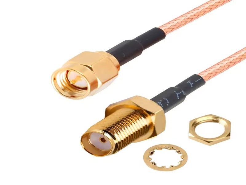
When signal problems appear in a system—unexpected noise, unstable communication, intermittent data loss—engineers often blame software, firmware, or active components first. Only later does attention turn to the cable. Yet in high-frequency systems, the cable is not a passive component. It is an active part of the signal path that directly shapes performance.
RF coaxial cables sit at the center of modern communication, measurement, medical imaging, industrial control, and wireless systems. They quietly carry high-frequency signals that are extremely sensitive to impedance mismatch, EMI, mechanical stress, and manufacturing variation. A cable that looks correct on paper may still distort signals, increase loss, or create reflections if its structure or assembly is even slightly wrong.
Many buyers search online for “what is an RF coaxial cable” because they are facing a real problem: a system that works inconsistently, a prototype that passes in the lab but fails in the field, or a sourcing decision that suddenly feels risky. The confusion is understandable. Terms like RF cable, coaxial cable, 50 ohm, 75 ohm, micro coax, and high-frequency cable are often used interchangeably—sometimes incorrectly.
An RF coaxial cable is a coaxial-structured cable specifically designed to transmit radio-frequency (RF) signals with controlled impedance, low loss, and strong EMI shielding. “RF” describes the signal type, while “coaxial” refers to the cable’s concentric physical structure. RF coaxial cables are used in wireless communication, medical equipment, industrial systems, and test instruments where signal integrity at high frequencies is critical.
Understanding what an RF coaxial cable really is—and how it should be selected or customized—can prevent costly redesigns and long-term reliability issues. Let’s start from the basics and build up.
What Is an RF Coaxial Cable?
An RF coaxial cable is a specialized transmission cable designed to carry radio-frequency (RF) signals with controlled impedance, low signal loss, and strong resistance to electromagnetic interference (EMI). Unlike general-purpose cables, RF coaxial cables are engineered as part of the signal path itself, meaning their internal structure directly affects signal quality, stability, and system performance.

In practical terms, an RF coaxial cable is not just a “wire.” It is a precisely engineered transmission line whose geometry, materials, and assembly quality determine whether high-frequency signals arrive cleanly, consistently, and predictably at their destination.
To fully understand what an RF coaxial cable is, it helps to separate the concept into three parts:
RF (the signal), coaxial (the structure), and RF coaxial cable (the engineered combination).
What Does “RF” Mean in RF Coaxial Cable?
“RF” stands for radio frequency, a range of electromagnetic signals typically spanning from tens of kilohertz (kHz) up to several gigahertz (GHz) or higher. At these frequencies, signals no longer behave like simple electrical current flowing through a wire. Instead, they propagate as electromagnetic waves, making them highly sensitive to impedance changes, reflections, and interference.
This is why RF signals demand special handling:
- Small impedance mismatches can cause reflections and signal loss
- Geometric inconsistencies can distort wave propagation
- External EMI can easily couple into poorly designed cables
Importantly, RF is not a cable type. It describes the signal. Many cables can carry low-frequency signals, but only properly designed cables can reliably carry RF signals without degrading performance.
What Makes a Cable “Coaxial”?

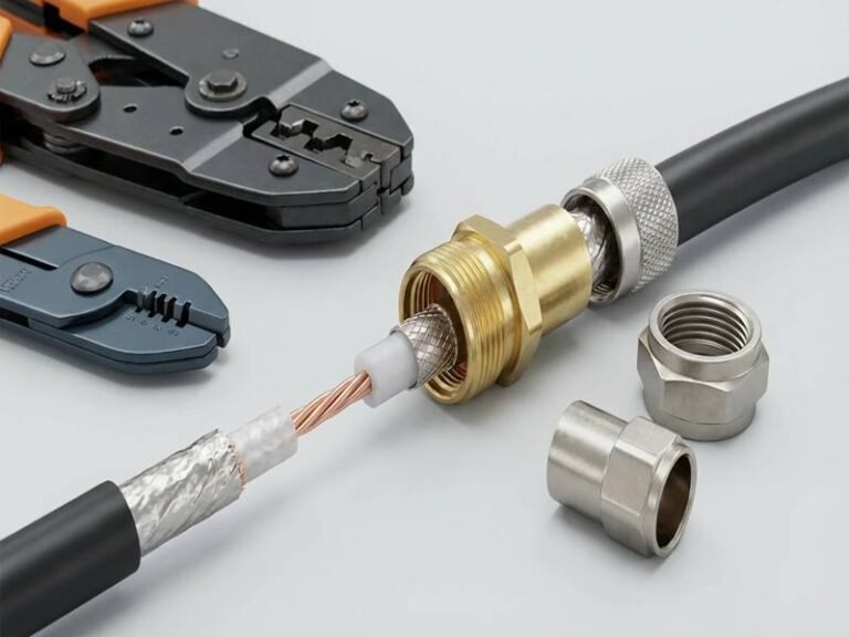
“Coaxial” refers to the concentric physical structure of the cable. In a coaxial design, all conductive elements share a common axis, which is essential for controlling electromagnetic behavior.
A typical coaxial structure includes:
- A center conductor that carries the signal
- A dielectric insulator that defines spacing and impedance
- A shielding layer (braid, foil, or both) that acts as the return path and EMI barrier
- An outer jacket that provides mechanical and environmental protection
This structure confines the electromagnetic field between the center conductor and the shield, preventing signal radiation and minimizing susceptibility to external noise. Without this coaxial geometry, high-frequency signals quickly become unstable and lossy.
What Is the Difference Between RF Cable and Coaxial Cable?
This distinction is one of the most common sources of confusion for buyers and non-RF engineers.
| Term | What It Describes | Common Misunderstanding |
|---|---|---|
| RF | A signal frequency range | Often mistaken as a cable type |
| Coaxial | A physical cable structure | Often assumed all coax is RF-ready |
| RF Coaxial Cable | Coaxial cable engineered for RF signals | Not all coax meets RF performance needs |
In simple terms:
- RF describes what kind of signal is being transmitted
- Coaxial describes how the cable is physically built
- RF coaxial cable is the combination of both, optimized for high-frequency signal integrity
A coaxial cable used for low-frequency video or control signals may look similar on the outside, but it may not meet RF requirements for impedance stability, shielding effectiveness, or frequency performance.
Why RF Coaxial Cables Are Not Interchangeable
One of the most important points for OEMs and engineers to understand is that RF coaxial cables are not interchangeable commodities. Two cables with similar appearance can behave very differently in real applications.
Key factors that differentiate RF coaxial cables include:
- Impedance accuracy and tolerance
- Dielectric material consistency
- Shield coverage and termination quality
- Mechanical stability under bending or vibration
Even small variations in these factors can lead to higher insertion loss, poor VSWR, or intermittent system behavior—especially at higher frequencies.
How RF Coaxial Cables Fit Into Real Systems
In RF systems, the cable must be treated as an active part of the signal chain, not a passive accessory. Its role is comparable to that of an RF component: if it is poorly specified or assembled, it can limit the performance of the entire system regardless of how good the electronics are.
This is why RF coaxial cables are widely used in applications such as:
- Wireless communication and antenna connections
- Medical imaging and diagnostic equipment
- Industrial RF sensing and control systems
- Test and measurement instruments
In all of these cases, the cable’s job is not just to connect two points, but to preserve signal integrity from source to destination.

An RF coaxial cable is a precision-engineered transmission line, defined by both the type of signal it carries (RF) and the structure that enables stable transmission (coaxial geometry). Understanding this distinction helps engineers and buyers avoid incorrect assumptions, reduce system-level risk, and make better decisions when selecting or customizing RF cable assemblies.
This foundational understanding also explains why specification clarity, manufacturing discipline, and proper assembly are critical—topics that become even more important as RF systems move from prototype to real-world deployment.
How Does an RF Coaxial Cable Work?
An RF coaxial cable works by guiding high-frequency signals through a controlled impedance path formed by the center conductor and surrounding shield. The coaxial structure confines the electromagnetic field, minimizes signal loss, and reduces susceptibility to external interference, ensuring stable transmission over distance.
How Does the Coaxial Structure Control Signal Loss?
In RF systems, impedance consistency is everything. The dielectric material and precise spacing between the conductor and shield define the cable’s characteristic impedance—commonly 50 ohms or 75 ohms. Any deviation creates reflections, increasing VSWR and reducing usable signal power.
Unlike low-frequency cables, RF coax cannot tolerate large geometric variation. Even connector transitions and assembly methods matter.
How Does Shielding Reduce EMI and Noise?
Shielding serves two purposes: it prevents external noise from entering the signal path, and it prevents the RF signal from radiating outward. Poor shielding continuity can turn a cable into an unintended antenna, degrading both the system and nearby electronics.
Which Types of RF Coaxial Cables Are Commonly Used?
Common RF coaxial cables include 50-ohm cables for RF communication and test systems, 75-ohm cables for video and broadcast, and micro coaxial cables for compact devices. Selection depends on frequency, size constraints, flexibility, and application environment.
Which RF Coaxial Cables Are 50 Ohm or 75 Ohm?
| Impedance | Typical Use | Key Priority |
|---|---|---|
| 50 Ω | RF communication, antennas, test equipment | Power handling, low reflection |
| 75 Ω | Video, broadcast, imaging | Signal fidelity, low attenuation |

Using the wrong impedance does not always cause immediate failure—but it almost always degrades performance.
What Is the Difference Between Standard and Micro RF Coaxial Cable?
Micro coaxial cables reduce outer diameter while maintaining impedance. They are essential for compact medical devices, consumer electronics, and embedded RF modules—but are far more sensitive to handling and assembly quality.
What Specifications Matter Most for RF Coaxial Cables?
When selecting or customizing an RF coaxial cable, performance problems rarely come from a single dramatic mistake. Instead, they are usually caused by small specification gaps—an impedance tolerance that was never confirmed, a bend radius that looked acceptable on paper, or a shielding detail that was assumed rather than defined.
In RF systems, specifications are not formalities. They are direct predictors of signal behavior. A cable that meets basic dimensional requirements but fails to meet RF-specific electrical or mechanical limits can quietly degrade performance, introduce instability, or shorten system life.
The most important RF coaxial cable specifications fall into four closely linked categories:
electrical performance, mechanical characteristics, shielding effectiveness, and interface consistency. All four must be considered together.
Electrical Specifications: The Foundation of RF Performance
Electrical parameters define whether an RF coaxial cable can carry a signal without distortion, reflection, or excessive loss. Among these, impedance is the most critical.
Key electrical specifications include:
- Characteristic impedance (commonly 50 Ω or 75 Ω)
- Impedance tolerance (often ±1 Ω or tighter for precision systems)
- Frequency range the cable is designed to support
- Insertion loss (attenuation) per unit length
- Return loss / VSWR limits
At RF frequencies, even minor impedance deviations can cause reflections that reduce effective signal power and increase noise. These effects compound over distance and are often misdiagnosed as component or firmware issues.
| Electrical Parameter | Why It Matters in Real Systems |
|---|---|
| Impedance value | Prevents reflections and mismatch |
| Impedance tolerance | Ensures consistency across cables |
| Frequency rating | Defines usable bandwidth |
| Insertion loss | Limits signal reach and margin |
| VSWR / return loss | Indicates transmission efficiency |
A cable that is “close enough” electrically at low frequency may be completely unsuitable for RF use.
Mechanical Specifications: When Physical Design Affects RF Stability
Mechanical characteristics are often underestimated in RF cable selection, yet they directly influence electrical stability over time.
Critical mechanical specifications include:
- Outer diameter (OD) and allowable tolerance
- Minimum bend radius (static and dynamic)
- Flex life under repeated movement
- Tensile strength and strain relief behavior

RF coaxial cables rely on precise geometry between the center conductor and shield. Excessive bending, stretching, or compression alters this geometry, which in turn alters impedance.
| Mechanical Parameter | RF Impact |
|---|---|
| OD tolerance | Affects impedance consistency |
| Bend radius | Prevents dielectric deformation |
| Flex life | Maintains long-term RF stability |
| Strain relief | Protects connector transitions |
In applications such as medical devices, test equipment, or moving industrial systems, mechanical stress is often the primary cause of RF performance drift, not initial electrical design.
Shielding Effectiveness: Controlling EMI and Signal Leakage
Shielding is not just about blocking noise—it is about controlling the electromagnetic field around the RF signal.
Key shielding-related specifications include:
- Shield type (braid, foil, or combined)
- Shield coverage percentage
- Shield resistance and continuity
- Shield termination method at connectors
Poor shielding does not always cause immediate failure. Instead, it often leads to inconsistent behavior that appears only under certain operating conditions, such as nearby motors, wireless devices, or changing grounding environments.
| Shielding Aspect | Risk if Not Properly Defined |
|---|---|
| Coverage percentage | EMI susceptibility |
| Termination method | Signal leakage and radiation |
| Continuity | Unstable noise performance |
| Ground reference | Ground loop or antenna effects |
In RF systems, shielding must be treated as part of the signal path—not as optional protection.
Connector Interface and Transition Specifications
The transition between the RF coaxial cable and its connector is one of the highest-risk points in the entire signal chain.
Important interface specifications include:
- Connector type and impedance rating
- Center conductor attachment method
- Shield termination style (360° vs partial)
- Dimensional control at the mating interface
Even a perfectly specified cable can underperform if the connector transition introduces impedance discontinuities. This is why RF cable performance cannot be separated from assembly method and connector selection.
Environmental and Material Specifications
Real-world environments often differ dramatically from lab conditions. Environmental specifications determine whether RF performance remains stable over time.
Common considerations include:
- Operating temperature range
- Resistance to oils, chemicals, or cleaning agents
- UV and aging resistance
- Halogen-free or low-smoke material requirements
Environmental stress accelerates mechanical and dielectric changes, which eventually show up as RF degradation.
Specification Trade-Offs: Why “More” Is Not Always Better
It is tempting to over-specify every parameter “just in case.” In reality, RF coaxial cable design involves trade-offs between size, flexibility, loss, durability, and cost.
For example:
- Smaller OD improves routing but increases loss
- Higher shielding improves EMI but reduces flexibility
- Tighter impedance tolerance improves RF but raises manufacturing difficulty
A good specification balances actual application needs, not theoretical extremes.
Summary Table: Core RF Coaxial Cable Specifications
| Specification Category | Primary Purpose |
|---|---|
| Electrical (impedance, loss) | Signal integrity |
| Mechanical (OD, bend radius) | Stability over time |
| Shielding | EMI control |
| Connector interface | Minimize transitions |
| Environmental | Long-term reliability |
The most important RF coaxial cable specifications are those that preserve signal integrity under real operating conditions, not just during initial testing. Electrical accuracy, mechanical stability, shielding continuity, and interface control must work together as a system.
For OEMs and engineers, clearly defining these specifications early—and validating them through drawings, samples, and controlled assembly—is the most effective way to reduce RF risk, avoid redesigns, and ensure consistent performance from prototype to production.
How Are RF Coaxial Cables Used in Real Applications?
RF coaxial cables are used in wireless communication, medical imaging, industrial equipment, test and measurement systems, and consumer electronics. Each application emphasizes different performance priorities such as low loss, flexibility, EMI control, or mechanical durability.
What Is RF Coaxial Cable Used For?
- Antenna connections
- Medical imaging and sensing
- Industrial RF systems
- Test and measurement instruments

Why Application Environment Changes Cable Design
A lab cable and a production cable are rarely the same. Movement, vibration, temperature, and installation constraints often matter more than raw electrical specs.
How Do You Choose or Customize an RF Coaxial Cable Assembly?
Choosing the right RF coaxial cable assembly requires understanding application conditions, defining electrical and mechanical requirements, and working with a manufacturer that can validate design assumptions through drawings, samples, and testing.
What Information Should You Provide Before Customization?
- Application description
- Frequency range
- Length and routing
- Connector preference
- Environmental exposure
How Does Engineering Support Reduce RF Cable Risk?
Engineering-driven customization—CAD drawings, pin definition, sample validation—prevents late-stage failures and costly redesigns.
Why Work with a Professional RF Coaxial Cable Manufacturer?
Professional RF coaxial cable manufacturers provide engineering support, controlled assembly processes, and consistent quality that off-the-shelf solutions often lack—especially for OEM and industrial applications.
Why Off-the-Shelf RF Cables Often Fail in OEM Projects
Generic cables rarely match real installation conditions. Small mismatches compound over time.
How Manufacturing Process and Inspection Affect RF Performance
Process consistency, not brand name, determines long-term RF stability.

Final Thoughts: From Definition to Reliable RF Performance
RF coaxial cables are not interchangeable commodities. They are engineered transmission systems that must align with signal requirements, mechanical realities, and manufacturing discipline.
At Sino-Conn, we support RF coaxial cable projects from specification review and drawing confirmation to rapid sampling and volume production. Whether you start with a part number, a drawing, or just a reference photo, our team helps translate requirements into a reliable, manufacturable RF cable solution.
If you are planning an RF coaxial cable or custom RF cable assembly project, contact Sino-Conn to discuss specifications, drawings, samples, and production—starting from 1 piece, with no MOQ.