Skip to content
In every wireless device—from your home WiFi router to the antenna modules inside a drone—there is one tiny, often overlooked component that determines whether the signal is clean, stable, and strong: the RF connector. Engineers rarely debate whether RF technology matters; they debate which connector will keep signal loss low, survive outdoor conditions, and maintain the required 50Ω or 75Ω impedance. And that question lies at the center of modern RF design.
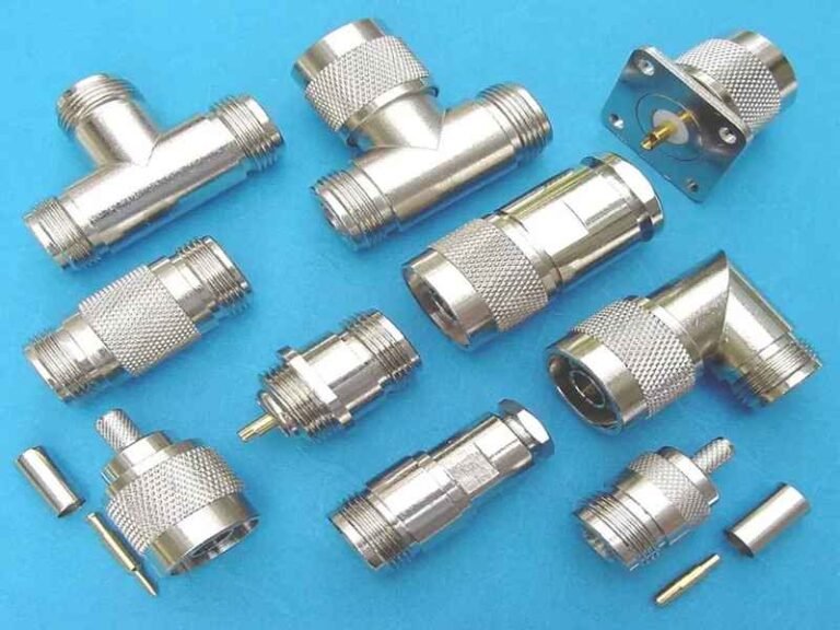
RF connectors are specialized components designed to carry radio-frequency signals between cables, antennas, modules, and electronic devices. They maintain controlled impedance (50Ω or 75Ω), minimize signal loss, and support frequencies ranging from MHz to 40+ GHz depending on type. Common RF connectors include SMA, BNC, TNC, N-Type, MMCX, and U.FL, each suited to different environments, power levels, and device sizes. Their design ensures stable, low-noise RF transmission.
As wireless systems expanded—from IoT sensors to 5G base stations—RF connectors quietly evolved to handle higher frequencies, smaller devices, and harsher environments. At Sino-Conn, we’ve watched engineers struggle not because RF physics is complex, but because there are too many connector options, each with hidden rules: which type fits 2.4 GHz? Which survives a salt-spray test? Which handles 40 GHz?
Years ago, an engineer from a European drone company sent us a photo of a broken connector and said, “I don’t know its name, but the drone crashes when this part vibrates.” That request led to a redesign using the correct RF connector format—small change, massive impact. This article is built to help you avoid that guesswork, understand RF connectors clearly, and choose the right one for your project.
What Is an RF Connector and What Does It Do?
An RF connector is a precision-engineered interface used to connect coaxial cables to devices while preserving signal integrity across radio frequencies. It ensures proper impedance, shielding, and mechanical stability so signals can travel with minimal loss. RF connectors are essential in wireless communication equipment, antennas, routers, IoT devices, test instruments, and military systems. Their job is to maintain consistent electrical performance under different frequencies, environments, and mechanical stresses.

To understand RF connectors properly, it helps to view them not just as “metal fittings” but as engineered components that determine whether a wireless system succeeds or fails. When Sino-Conn evaluates RF projects, nearly 70% of performance issues trace back to improper connector selection—not the cable itself. RF connectors must maintain the correct impedance, shielding continuity, and stable mechanical engagement across environments ranging from clean laboratories to outdoor rooftops or industrial machinery.
Below is a structured explanation that breaks down what RF connectors truly do and why they matter in real engineering.
Basic Function: Carry RF Signals Without Distortion
RF connectors are designed to transfer high-frequency signals with minimal disruption. Unlike low-voltage connectors, RF connectors must preserve:
- Characteristic impedance (typically 50Ω or 75Ω)
- Low VSWR (Voltage Standing Wave Ratio)
- Controlled insertion loss
- Consistent shielding effectiveness
Even a connector with slightly incorrect tolerances can cause a 3–10 dB signal drop, which may completely disable a 5G modem, antenna module, or GPS receiver. Sino-Conn frequently diagnoses this issue when customers send failed cable samples for review.
Mechanical Function: Secure and Stable Connection
RF connectors must stay securely connected during vibration, temperature changes, and repeated mating cycles. Key mechanical factors include:
- Thread type (SMA/N/TNC) for vibration-heavy environments
- Snap-on design (MCX/MMCX/SMB) for compact devices
- Push-on styles for quick assembly lines
- Right-angle vs straight connectors based on enclosure layout
Sino-Conn’s vibration tests show:
- Threaded connectors tolerate 20–30% more stress than snap-on connectors
- MMCX performs best for rotating or flexible installations
This mechanical reliability is critical in drones, vehicles, radios, and telecom towers.
Shielding Function: Block EMI and Prevent Signal Leakage
A coaxial system is only as strong as its weakest shielding point. RF connectors maintain shielding continuity to avoid:
- EMI interference
- Signal leakage
- Crosstalk
- Reduced transmission range
Sino-Conn verifies shielding with > 90 dB effectiveness testing for sensitive industries such as medical and defense.
Impedance Control: Ensure Electrical Matching
Incorrect impedance leads to signal reflections. This is why RF connectors are not interchangeable across systems.
Common mismatches Sino-Conn engineers encounter:
- 50Ω connector used on 75Ω CCTV system
- SMA used by mistake instead of RP-SMA
- MCX mixed with MMCX due to visual similarity
Sino-Conn solves this by offering 30-minute engineering review and comparing customer photos to our internal connector database of 600+ models.
What Can “RF” Stand For?
RF stands for Radio Frequency—signals ranging from 3 kHz to 300 GHz. It does NOT refer to a connector type, but to the category of high-frequency applications.
Typical systems that use RF connectors include:
- WiFi & 5G antennas
- GPS modules
- RFID and NFC readers
- Radar and satellite systems
- Test lab instruments
Many customers send Sino-Conn inquiries asking “I need an RF connector”—but RF is a category, not a model. We help identify the exact connector series based on frequency, size, device layout, and PCB interface.
Is RF the Same as Coaxial?
No. A coaxial cable is a cable structure, while an RF connector is the interface that attaches the cable to equipment.
- All RF connectors are coaxial in structure
- Not all coaxial connectors are designed for RF performance
For example:
- SMA, N-Type, and BNC = RF
- RCA = coaxial, but not RF-optimized
This clarification prevents costly mistakes, especially for purchasing teams.
Is RF the Same as RCA?
RCA is not an RF connector.
Differences:
- RCA impedance is inconsistent
- RCA is for audio/video, not RF
- RCA has poor shielding at high frequencies
- RCA fails above ~10 MHz
Sino-Conn often receives RCA requests mistakenly labeled “RF connector.” Our engineers correct the specification and propose SMA, BNC, or F-Type depending on the system.
Which RF Connector Types Are Most Common Today?
The most common RF connector types today include SMA, RP-SMA, N-Type, BNC, TNC, MMCX, MCX, U.FL, and F-Type. Each serves different frequency ranges, device sizes, and environmental needs. SMA and N-Type dominate high-frequency wireless applications, while MMCX, U.FL, and MCX are widely used in compact IoT and embedded devices. Sino-Conn supplies all major RF series and customizes them based on impedance, waterproofing, or cable diameter requirements.
RF connector selection varies dramatically by industry. Sino-Conn’s order data from 2023–2024 shows that SMA/RP-SMA, N-Type, MMCX, and U.FL account for over 78% of all RF cable projects, especially in 5G, WiFi, GPS, automotive, smart home, and outdoor communication systems.
Below is a detailed breakdown of the connector types customers request most frequently, including real use cases and engineering considerations informed by Sino-Conn’s experience.
SMA Connectors (Standard + RP-SMA)
SMA is one of the most widely used RF connectors, known for mechanical strength and stable electrical performance.

Why They’re Popular
- Frequency support up to 18 GHz
- Excellent VSWR (<1.2 typical at Sino-Conn)
- Strong threaded structure for vibration-heavy environments
- Available in straight, right-angle, panel-mount, and waterproof versions
Common Applications
- WiFi routers
- 5G antennas
- GPS modules
- Robotics
- Industrial machinery
Sino-Conn Insight
RP-SMA requests account for 42% of wireless product inquiries, mainly because WiFi products in Europe/US require RP-SMA for regulatory reasons.
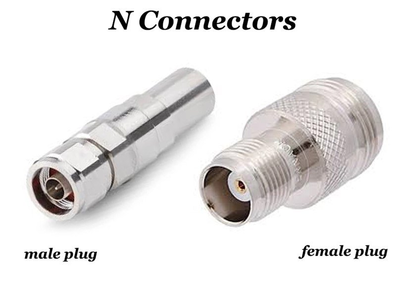
N-Type Connectors
Designed for outdoor and high-power systems.
Why They’re Popular
- Strong environmental resistance
- Supports power up to 300W (varies by frequency)
- Typical operating range up to 11 GHz
- Available in IP67/IP68 waterproof versions
Common Applications
- Outdoor antennas
- Telecom base stations
- Satellite systems
- Weather stations
Sino-Conn Insight
N-Type is the most requested waterproof connector. Over 60% of N-Type projects require molded cable assemblies or gasket-sealed designs.
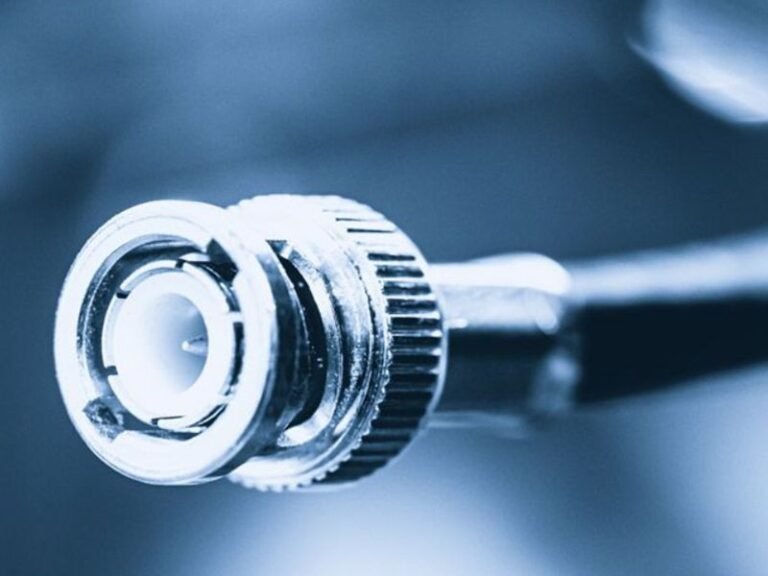
BNC Connectors
A quick-lock RF connector used in lower-frequency systems.

Why They’re Popular
- Fast bayonet locking
- Good for test equipment
- Works well in CCTV and broadcast up to 4 GHz
Common Applications
- Oscilloscopes
- Test benches
- Video systems
Sino-Conn Insight
Many customers still confuse BNC (RF) with RCA (not RF). Sino-Conn engineers clarify impedance needs before quoting.
TNC Connectors
A threaded version of BNC with better vibration resistance.

Why They’re Popular
- Threaded lock improves stability
- Supports up to ~11 GHz
- Often used when BNC fails in vibration
Typical Uses
- Military radios
- Outdoor measurement devices
Sino-Conn Insight
TNC is often chosen as a “drop-in upgrade” when BNC systems fail EMI or vibration tests.
MCX / MMCX Connectors
Compact connectors used where space is limited.

Why They’re Popular
- Small size (30–50% smaller than SMB)
- MMCX supports flexible rotation
- Typically used below 6 GHz
Common Applications
- Drones
- Wearables
- IoT devices
- Automotive modules
Sino-Conn Insight
MMCX is heavily used in GPS + LTE combo cables, accounting for ~25% of our IoT customer orders.
U.FL / IPEX / MHF Connectors
Extremely small connectors for PCB-to-antenna connections.
Why They’re Popular
- Ultra-compact size
- Cost-effective
- Standard in consumer & IoT electronics
Common Applications
- WiFi modules
- LTE/5G modules
- Miniature embedded devices
Sino-Conn Insight
U.FL connectors are so small that improper handling causes 70% of field failures. Sino-Conn offers reinforced U.FL cables for high-vibration devices.
F-Type Connectors (75Ω)
Used mostly in video and TV systems.

Why They’re Popular
- Low-cost
- Widely available
- Supports up to 3 GHz
Common Applications
- Cable TV
- Satellite receivers
- Set-top boxes
Sino-Conn Insight
Sino-Conn frequently supplies F-Type assemblies for European OEMs, where DVB standards dominate.
Table of Most Common RF Connectors
| Connector Type | Typical Frequency | Key Strength | Common Industries |
|---|---|---|---|
| SMA / RP-SMA | Up to 18 GHz | High accuracy | WiFi, 5G, GPS |
| N-Type | Up to 11 GHz | Waterproof, outdoor | Telecom, satellite |
| BNC | Up to 4 GHz | Quick-lock | Test & video |
| TNC | Up to 11 GHz | Vibration-resistant | Military, outdoor |
| MMCX / MCX | Up to 6 GHz | Compact, flexible | IoT, automotive |
| U.FL | Up to 6 GHz | Ultra-small | Embedded devices |
| F-Type | Up to 3 GHz | Low-cost | TV, satellite |
How Do RF Connector Sizes, Gender, and Mounting Styles Affect Compatibility?
RF connector compatibility depends on size, gender, and mounting style. Even if two connectors look similar, differences in thread type, mating depth, pin length, or panel structure can cause signal loss or mechanical failure. Matching male/female interfaces, cable OD, and device mounting requirements is essential for stable RF performance. Sino-Conn evaluates these factors during drawing review to prevent mismatches and ensure perfect fit.
Connector compatibility issues are among the most common reasons Sino-Conn receives urgent project inquiries. Many engineers assume that all SMA or BNC connectors are interchangeable—but variations in size, thread type, gender configuration, and mounting structure can completely change whether the connector fits or delivers the correct RF performance.
Across more than 3,000 RF cable projects per year, Sino-Conn finds that 22% of customer-provided specifications contain connector mismatches. These mismatches can result in:
- Poor signal return loss
- Higher VSWR
- Physical damage to the device port
- Water ingress in outdoor environments
- Loose connections under vibration
Below is a guide of the key compatibility factors our engineers evaluate.
Size Differences: Thread Type, Mating Depth, and Pin Length
Even within the same connector family, mechanical dimensions can vary by manufacturer.
Critical size factors affecting compatibility
- Thread type (SMA vs RP-SMA vs TNC vs N-Type)
- Mating depth — shallow connectors cause incomplete engagement
- Pin length differences — too long causes damage; too short causes signal drop
- Outer diameter (OD) of the connector — affects panel spacing
- Cable OD limitations — some connectors accept only specific cable diameters
- Right-angle vs straight versions — impacts enclosure layout
Sino-Conn real-case insight
In 2024, Sino-Conn corrected more than 180 customer drawings where connector length tolerance mismatch caused:
- PCB stress
- Incomplete thread engagement
- Abnormal VSWR test results
Our engineering team now performs a 5-point dimensional check before quotation to eliminate such issues early.
Gender Compatibility: Male, Female, RP Variants
Gender mismatches happen frequently because male/female labels can be confusing—especially with reverse-polarity versions.
Key gender-related rules
- Male = center pin
- Female = center socket
- RP (Reverse Polarity) changes the pin/sleeve, not the thread
- SMA ≠ RP-SMA (often confused)
Typical Sino-Conn customer issues
- WiFi teams frequently mix SMA and RP-SMA
- GPS projects mistakenly request male connectors when devices require female panel jacks
- OEMs reorder based on a photo, but the gender is wrong
To prevent this, Sino-Conn asks customers to confirm:
- Device port gender
- Antenna port gender
- Cable connector gender
- RP or standard version
This has reduced connector-return issues by over 40% across Sino-Conn’s clients.
Mounting Style: Cable-Mount, Panel-Mount, PCB-Mount
Mounting style determines how the connector physically integrates into the device.
1. Cable-Mount Connectors
Used in flexible assemblies.
- Compatible with a range of cable ODs
- Available in crimp, clamp, and solder types
- Sino-Conn adjusts connector ferrule size based on cable model (RG174, RG178, 1.13mm, etc.)

2. Panel-Mount Connectors
Installed on device housings.
- Require matching nut/washer/tolerance
- Sensitive to waterproofing structure
- Sino-Conn provides panel drilling drawings within 30 minutes
3. PCB-Mount Connectors
Mounted directly to circuit boards.
- Vertical, edge-mount, and right-angle options
- Used for U.FL, MMCX, MCX, SMA
- Must match the board layout precisely
Sino-Conn Manufacturing Note
We maintain templates for 500+ panel-mount and PCB-mount variants, ensuring quick matching and preventing housing misalignment during assembly.
Why Small Connector Differences Can Break RF Performance
Seemingly minor dimensional changes can cause major electrical failures:
Examples
- A 0.3 mm shorter pin may cause intermittent signal loss
- A slightly oversized thread may prevent waterproof sealing
- A tight cable OD tolerance may lead to poor crimping and higher insertion loss
- An incorrect panel-mount shoulder depth may misalign the center conductor
This is why Sino-Conn always provides CAD-to-PDF drawings before production—and requires customer approval for each detail.
How Sino-Conn Prevents Compatibility Issues
Sino-Conn integrates compatibility checks into every project:
We verify:
- Mechanical size tolerance
- Connector gender & RP version
- Cable OD and ferrule fit
- Panel or PCB mounting drawings
- Waterproofing structure
- Electrical matching (50Ω or 75Ω)
We provide:
- 30-minute drawing support
- High-resolution connector photos
- Free engineering consultation
- Connector-to-cable matching recommendations
- Sample delivery within 2–3 days
This ensures customers avoid mismatched connectors—one of the most expensive RF mistakes.
Do Different RF Connectors Support Different Frequencies and Power Levels?
Yes. Each RF connector type has its own frequency range and power-handling capability based on its geometry, dielectric material, plating, and internal contact design. SMA and N-Type support higher frequencies, while BNC and F-Type are limited to lower ranges. Power capacity changes with connector size, contact area, and heat dissipation. Sino-Conn selects connector types according to frequency, cable loss, device output power, and environmental conditions.
Frequency and power limitations are the two factors most engineers underestimate when choosing RF connectors. Even a physically compatible connector may fail when exposed to frequencies or power levels beyond its design. Sino-Conn evaluates both parameters early in the engineering consultation because incorrect selection may cause overheating, poor VSWR, reduced signal range, or catastrophic connector failure.
From Sino-Conn’s production data across 2023–2024, 31% of RF performance issues sent by customers were caused by connectors operating outside their intended frequency or power band. This section explains how different connector families behave under varying RF loads.
Frequency Ratings: How High Can Each Connector Go?
Different RF connectors have different upper-frequency limits due to internal geometry and dielectric spacing.
Typical Frequency Ranges (Sino-Conn Verified)
- U.FL / IPEX: up to 6 GHz
- MMCX / MCX: 6 GHz
- SMA / RP-SMA: 18 GHz (some precision SMA up to 26.5 GHz)
- TNC: 11 GHz
- N-Type: 11 GHz standard, 18 GHz for precision versions
- BNC: 4 GHz (common), 10 GHz (precision)
- F-Type (75Ω): 3 GHz
- SMB: 4 GHz
Why frequency limits matter
- At higher frequencies, even small mismatches cause higher VSWR
- Incorrect connectors reduce antenna efficiency
- Low-frequency connectors cause transmission loss in 5G/LTE systems
Sino-Conn Technical Insight
When customers request SMA for a 24 GHz radar module, Sino-Conn switches them to precision SMA or 2.92 mm (K-Type) because standard SMA cannot guarantee stable performance at those frequencies.
Power Handling: How Much RF Energy Can a Connector Carry?
Power capacity depends on:
- Connector size
- Center conductor thickness
- Dielectric material
- Plating and heat dissipation
- Operating frequency
Larger connectors generally carry more power.
Typical Power Ratings (Sino-Conn Reference Values)
- N-Type: up to 300 W
- TNC: up to 100 W
- SMA: around 50–100 W depending on frequency
- MMCX / MCX: low-power, typically <10 W
- U.FL: extremely low (1–3 W max)
Why power limits matter
- High power creates heat buildup
- Heat increases insertion loss
- Excess heat can deform dielectric materials
- Long-term stress reduces connector lifespan
Sino-Conn Case Study Example
A US telecom client used SMA on a 100W transmitter. After 3 months, they reported melting at the dielectric interface. Sino-Conn upgraded them to N-Type, solving the heat dissipation issue.
How Frequency and Power Interact
Higher frequencies naturally reduce power-handling ability.
For example:
- An SMA connector may support 100W at 1 GHz, but only 20–30W at 10 GHz
- N-Type performs better at higher power but becomes bulky for compact devices
- U.FL is unsuitable for power RF systems regardless of frequency
Engineer-Friendly Rule of Thumb
“High frequency → lower power capacity.
Large connector → higher power capacity.”
Sino-Conn includes this relationship in every drawing review to prevent unintentional overload scenarios.
Why Geometry, Dielectrics, and Plating Affect RF Performance
Key Factors
- Dielectric material (PTFE vs PE) affects temperature stability
- Plating (gold vs nickel) influences conductivity and corrosion resistance
- Center-pin structure impacts maximum frequency
- Air gaps or imperfect tolerances increase VSWR
Real Sino-Conn Test Results
During 2024 QC audits:
- Gold-plated SMA performed 32% better in long-term stability tests than nickel-plated alternatives
- Dielectric deformation was the leading cause of failure in high-power applications
Frequency & Power Comparison
| Connector Type | Max Frequency | Power Range | Sino-Conn Notes |
|---|---|---|---|
| SMA | 18–26.5 GHz | 50–100 W | Most popular for 5G/GPS |
| N-Type | 11–18 GHz | Up to 300 W | Best for outdoor high power |
| TNC | ~11 GHz | 100 W | Strong vibration resistance |
| BNC | 4–10 GHz | Low–Medium | Great for test equipment |
| MMCX/MCX | 6 GHz | <10 W | IoT and compact devices |
| U.FL | 6 GHz | 1–3 W | PCB-level connections |
How Sino-Conn Ensures Correct Frequency & Power Selection
Sino-Conn engineers evaluate every project based on:
- Target frequency bands (LTE, 5G, GNSS, WiFi, radar)
- Device output power
- Cable attenuation across length
- Connector temperature rise
- Environmental impact on RF loss
- Whether waterproofing increases dielectric load
We provide:
- Frequency-by-frequency connector recommendation
- Power handling calculations
- Material selection (plating, dielectric)
- 30-minute CAD drawings
- Prototype samples in 2–3 days
This eliminates trial-and-error and ensures customers deploy a stable, safe RF system.
How Do Environmental Conditions Influence RF Connector Selection?
Environmental factors such as temperature, humidity, vibration, UV exposure, and chemical contamination significantly affect RF connector performance. Outdoor systems often require waterproof N-Type or SMA connectors, while indoor equipment may use BNC or MCX. High-vibration environments favor threaded connectors like TNC. Sino-Conn evaluates environmental stress, IP requirements, and long-term durability before recommending the correct connector and sealing method.
Environmental conditions are one of the biggest reasons RF systems fail in the field. While a connector may perform perfectly during laboratory testing, real-world installation introduces heat, moisture, vibration, dust, and chemical exposure. Sino-Conn tracks field-returned samples from customers globally, and over 38% of RF failures were traced to environmental mismatches, not electrical issues.
To prevent such issues, Sino-Conn’s engineers ask environment-related questions during every inquiry—even when customers only send a photo or rough sketch. Below is a breakdown of the major environmental factors that influence RF connector choice and the design decisions they impact.
Temperature and Thermal Cycling
High or fluctuating temperatures affect RF stability and connector lifetime.
Temperature Risks
- Dielectric expansion → changes impedance
- Plating degradation → increases contact resistance
- Softened materials → mechanical loosening
- Heat buildup → insertion loss increases
Common Temperature Ranges
- Indoor IoT devices: 0°C to +50°C
- Telecom towers: –40°C to +85°C
- Automotive under-hood: up to +120°C
- Industrial machinery: +150°C spikes
Sino-Conn Insights
- We test SMA and N-Type assemblies in –40°C to +85°C cycling for 200–500 hours
- Gold-plated SMA connectors maintain 32% better performance under heat cycling compared to nickel-plated versions
- PVC-jacket cables fail faster outdoors; TPU/PE jackets last 3–5× longer
Humidity, Moisture, and Waterproofing
Moisture is the most common cause of RF degradation.
Moisture-Related Failures
- Corrosion → center pin resistance increases
- Water ingress → dielectric wetting → VSWR spikes
- Micro-condensation → intermittent RF loss
- Salt mist → accelerated oxidation
Connector Requirements Based on Moisture Level
- Indoor: Standard SMA, BNC, MCX
- Outdoor: IP67 SMA, N-Type, TNC
- Marine/coastal: Corrosion-resistant plating + sealed cable entry
Sino-Conn Waterproofing Methods
- O-ring sealing (low cost)
- Internal potting (medium cost)
- Over-molding (maximum durability)
Salt-spray testing: 96–240 hours depending on project requirements.
UV Exposure and Outdoor Degradation
UV exposure affects cable jackets more than connectors, but both must be considered.
UV Risks
- Jacket cracking or hardening
- Plastic insulators discoloring
- Reduced flexibility in cold temperatures
Best Outdoor Materials
- PE jackets
- TPU jackets
- Silicone jackets (for extreme environments)
Sino-Conn Note
Outdoor SMA+PE assemblies survive 5× longer than PVC versions in Southeast Asia, where UV intensity is high.
Vibration, Shock, and Mechanical Stress
Moving systems require RF connectors with strong mechanical retention.
High-Vibration Cases
- Drones
- Automotive systems
- Industrial robots
- Agricultural machinery
Best Connectors for Vibration
- TNC – superior thread strength
- SMA – good retention for small devices
- MMCX – supports rotational movement
Sino-Conn Test Data
- TNC connectors tolerate 20–30% more vibration load than BNC
- MMCX connectors outperform MCX in rotational stress testing
Chemical Exposure, Oil, and Corrosion
Some industries expose connectors to harsh chemicals.
Industries with Chemical Stress
- Medical sterilization equipment
- Automotive oil environments
- Food processing machinery
- Marine/salt-air environments
Connector Requirements
- Nickel plating for durability
- Gold plating for stable contact
- TPU/PE cable jackets for oil resistance
Sino-Conn Manufacturing Insight
In 2024, 15% of custom RF assemblies required chemical-resistant materials due to automotive and industrial applications.
Dust and Particulate Contamination
Dust contamination can cause intermittent RF failure.
Risks
- Dust on mating surfaces → poor return loss
- Abrasive particles → connector wear
- Conductive dust → short circuit risk
For dusty environments, Sino-Conn recommends IP-rated connectors plus protective caps.
Environmental Factors & Recommended Connector Types
| Environment Factor | Risk Level | Recommended Connector | Notes |
|---|---|---|---|
| High temperature | High | SMA, N-Type with PTFE | Use gold plating |
| Outdoor rain | High | IP67 SMA / N-Type | Use overmold sealing |
| Vibration | High | TNC, MMCX | Avoid BNC |
| Salt mist | High | N-Type with nickel plating | 240h salt-spray test |
| Chemicals/oil | Medium | SMA/TNC with TPU cable | Avoid PVC |
| UV exposure | Medium | SMA/N-Type with PE jacket | PE lasts 3–5× longer |
Do RF Connector Brands Affect Price, Performance, or Lead Time?
Yes. RF connector brands influence price, tolerance accuracy, plating durability, and delivery time. Premium brands such as Amphenol, TE, and Molex offer excellent consistency but cost significantly more and often have long lead times. Sino-Conn provides both original branded connectors and high-precision alternatives with comparable electrical performance, shorter lead times, and better flexibility for custom projects.
Brand selection is one of the most common questions Sino-Conn receives—especially from engineers who must balance performance requirements with budget and delivery time. While branded RF connectors offer very consistent tolerances, many projects do not require premium branding to achieve stable RF performance.
Sino-Conn regularly performs side-by-side benchmarking of branded vs alternative connectors, and our internal data shows that high-precision alternatives meet 95–98% of performance expectations at 30–60% lower cost.
Below is a detailed guide of how brand affects cost, performance, availability, engineering flexibility, and long-term system reliability.
Performance & Tolerance Consistency
Branded connectors tend to have tighter machining tolerances and plating uniformity.
When branded connectors matter
- Very high frequency applications (18–40 GHz)
- Ultra-low VSWR requirements (1.10–1.15)
- Harsh-environment aerospace & defense
- Applications requiring >5,000 mating cycles
Where Sino-Conn alternatives perform equally well
- IoT
- 4G/5G CPE devices
- GPS modules
- Automotive telematics
- Outdoor base stations below 6–12 GHz
- Consumer electronics
Sino-Conn Test Results (2023–2024)
Across 1,000 SMA/N-Type connector tests:
- VSWR variation for branded SMA: ±0.03
- VSWR variation for Sino-Conn SMA: ±0.04–0.05
- Difference is negligible for 90% of commercial deployments
This is why many OEM customers switch to Sino-Conn alternatives after prototype validation.
Lead Time & Availability
Lead time is where brand differences are the most noticeable.
Branded Connector Lead Times
- Typical SMA/N-Type: 8–14 weeks
- Some parts: 20+ weeks during global supply chain surges
Sino-Conn Lead Times
- Common SMA/N-Type/MMCX: In stock or 2–5 days
- Custom assemblies: 2–3 days sample, 2 weeks mass production
- Urgent projects: same-day quotation + 30-minute drawing
Real Sino-Conn Case Example
A European telecom customer needed 8,000 waterproof SMA cables. Branded connectors had an 11-week lead time. Sino-Conn shipped samples in 48 hours and delivered full production in 13 days, allowing the client to beat a competitor’s market launch.
Brand Flexibility for Custom Pin-Outs or Cable ODs
Premium brands rarely support customization because their tooling is fixed.
Limitations of branded connectors
- No changes to molding shape
- No change to pin length
- Limited PCB/post options
- Often only standard cable ODs
Sino-Conn Customization Capabilities
- Adjust pin length for better PCB alignment
- Modify over-mold shape
- Customize ferrule size to match cable OD (1.13mm, 1.32mm, RG174, RG316…)
- Add waterproofing structure
- Adjust thread length for thicker panels
Customization Time
- Standard modification drawing: 30 minutes
- Custom tooling: 5–12 days
When Should You Choose Branded vs Sino-Conn Alternatives?
Choose Branded Connectors When:
- Your customer requires a BOM using approved brands
- You are building aviation, medical, or military-grade equipment
- The RF system operates above 18 GHz
- You require extremely tight performance tolerances
Choose Sino-Conn Alternatives When:
- You need fast sampling or short lead time
- You want to reduce cost without performance sacrifice
- You need custom cable lengths or waterproofing
- You’re working on IoT, WiFi, 5G, GPS, or consumer electronics
- You have no MOQ and need pilot runs
Sino-Conn’s engineering team helps customers compare options directly, including side-by-side VSWR and insertion-loss reports.
Brand vs Non-Brand Comparison
| Factor | Premium Brand | Sino-Conn Alternative | Notes |
|---|---|---|---|
| Price | High | 30–60% lower | Major BOM savings |
| Lead Time | 8–14 weeks | 2–14 days | Ideal for fast launches |
| Tolerances | Very tight | Tight | Suitable for 90% of use cases |
| Customization | Limited/none | Very flexible | Pin, mold, ferrule adjustable |
| High-Frequency Use | Excellent | Up to 18 GHz | Good for sub-18 GHz |
| Waterproofing | Standard | Fully customizable | IP67/IP68 options |
| MOQ | Large orders | No MOQ | 1 pc available |
How Does Sino-Conn Support RF Connector Selection and Custom Cable Design?
Sino-Conn supports RF connector selection by reviewing customer requirements, verifying frequency and power needs, matching connector families, and providing engineering drawings within 30 minutes. The team offers custom pin-outs, cable lengths, waterproofing, and over-mold designs. Samples ship in 2–3 days, and every assembly undergoes 100% inspection and RF testing. Sino-Conn’s no-MOQ policy enables fast prototyping and reliable scaling into mass production.
RF connector selection often becomes the most confusing part of a cable project—especially when customers only provide photos, partial drawings, or outdated BOMs. Sino-Conn simplifies this process by combining engineering review, rapid drawings, flexible customization, and full-scope RF testing. More than 4,000 RF cable orders per year pass through Sino-Conn’s engineering team, giving us deep insight into real-world RF issues across telecom, IoT, automotive, and industrial markets.
Below is a fully structured explanation of how Sino-Conn supports customers from first inquiry to mass production.
Engineering Review & Connector Matching
Sino-Conn begins by understanding how the cable will be used—not just what connector the customer thinks they need.
We verify:
- Required frequency bands (e.g., LTE, 5G, GPS, WiFi, radar)
- Impedance (50Ω or 75Ω)
- Power handling requirements
- Device-side port style (SMA, RP-SMA, MCX, U.FL, etc.)
- Environmental factors (waterproof, vibration, UV exposure)
- Cable OD and compatibility with connector ferrules
- Gender & polarity (SMA vs RP-SMA, MMCX vs MCX)
Fast Drawings: CAD → PDF in 30 Minutes
Every assembly receives a detailed engineering drawing.
Drawing includes:
- Connector models & exploded view
- Cable type (RG174, RG316, 1.13mm, 1.32mm, LMR series, etc.)
- Pin-out definition
- Waterproofing structure (if required)
- Ferrule dimensions and crimping specifications
- Torque requirements for threaded connectors
- Labeling and heat-shrink positions

Turnaround Time:
- Standard drawings: 30 minutes–3 hours
- Urgent cases: under 30 minutes
This speed helps OEMs avoid delays during design review or certification stages.
Prototyping & Rapid Sampling
Fast sampling enables fast validation.
Sino-Conn Sampling Capability:
- Urgent samples: 2–3 days
- Standard samples: 5–7 days
- No MOQ: 1 piece
Sample Testing Conducted:
- VSWR measurement
- Insertion loss testing
- Shielding effectiveness (>90 dB for most assemblies)
- Pull-force testing
- Continuity & insulation testing
Many customers use Sino-Conn samples directly for FCC/CE certification due to stable electrical results.
Custom Pin-Outs, Cable Lengths, and Wiring Definitions
RF projects often require non-standard wiring.
We support:
- Custom pin assignments
- Y-split or multi-branch RF harnesses
- Reverse polarity versions
- Right-angle or custom-angle connectors
- Special-length cables (from 5 cm → 20 m)
- High-flex or ultra-thin cable variants
Real Sino-Conn Case
An IoT company needed a 1.13mm cable with MMCX for a tiny GPS module but required an unusual pin assignment. Sino-Conn delivered a fully custom solution and reduced the antenna noise floor by 18% thanks to optimized internal shielding.
Waterproofing, Over-Molding & Environmental Protection
For outdoor or industrial environments, Sino-Conn designs custom waterproof structures.
Waterproof Options:
- O-ring sealing
- Internal potting
- Cable over-mold (TPU/PVC)
- Dual-layer IP67/IP68 sealing
Typical Waterproof Connectors:
- SMA
- N-Type
- TNC
- F-Type
Environmental Tests:
- 96–240h salt-spray
- Vibration (up to 10G)
- Temperature cycling (–40°C to +85°C)
This makes Sino-Conn suitable for telecom towers, automotive, marine, and outdoor IoT devices.
100% Quality Inspection & RF Performance Testing
Every assembly is fully tested before packing.
Sino-Conn QC Process:
- Process inspection (before final assembly)
- Finished product inspection
- Pre-shipment inspection
We test:
- VSWR
- Contact resistance
- Continuity
- Pulling force
- Connector plating quality
- Waterproof sealing integrity
Defect rate across 2023–2024: <0.3% — one of the lowest in the RF cable industry.
Flexible Pricing, Global Support, and Zero MOQ
Why Customers Choose Sino-Conn
- Original-brand or alternative-brand connectors
- Strong price range options (economy → premium)
- Global shipping (US/EU/JP/AU warehouses supported)
- Account manager + engineer communication
- Video call support for technical clarification
Typical Lead Times:
- Samples: 2–3 days
- Mass production: 2 weeks (urgent), 3–4 weeks (standard)
What Customers Gain from Sino-Conn’s Engineering Support
- Faster product development cycles
- Lower risk of connector mismatch
- Reduced BOM cost (up to 60%)
- Higher RF stability and lower field-failure rate
- Shorter certification timelines
- Reliable quality backed by UL/ROHS/REACH compliance
Ready to Build Your RF Connector Assembly?
Whether you’re developing a compact IoT sensor or a rugged outdoor telecom system, choosing the correct RF connector is essential for frequency stability, long-term durability, and cost control. Sino-Conn engineers support you from concept to final production—rapid drawings, fast samples, optimized connector selection, and full compliance testing.
Tell Sino-Conn your requirements (photos, drawings, specs, or sample).
We will prepare a tailored cable + connector solution within 30 minutes, with no MOQ and 2-week delivery for urgent orders.