Skip to content
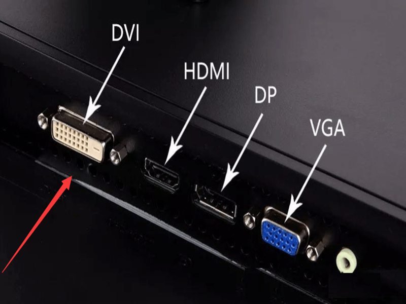
Modern display systems are often judged by what users see on the screen—but what engineers worry about is how that image gets there. In many real-world projects, display failures are not caused by GPUs, panels, or software, but by something far more basic: the display cable. Among the many display interfaces available today, DVI cables continue to appear in industrial equipment, medical systems, and long-lifecycle OEM products—sometimes long after consumer electronics have moved on.
This often confuses buyers. If HDMI and DisplayPort are newer, faster, and more common, why does DVI still exist? Why do some systems still require it? And what exactly is a DVI cable used for in real applications?
A DVI cable is a video signal cable designed to transmit digital and/or analog display data between a source device and a display. It is commonly used in monitors, industrial displays, medical imaging systems, and embedded equipment where signal stability, connector robustness, and long-term compatibility are critical. Different DVI types (DVI-D, DVI-I, single-link, dual-link) support different resolutions and applications.
Behind that simple definition is a set of design decisions that affect reliability, compatibility, and manufacturability. Many projects run into trouble not because DVI is outdated, but because its type, usage context, or specifications were misunderstood. To choose—or customize—the right DVI cable, it’s essential to understand what it is, how it works, and where it still makes sense today.
Let’s start with the basics—and then move into the realities engineers and buyers face in actual products.
What Are DVI Cables?
A DVI cable is a display interface cable used to transmit video signals from a source device to a display. Depending on the type, it can carry digital signals, analog signals, or both. DVI cables are commonly used in monitors, industrial equipment, and embedded systems where stable image transmission and mechanical reliability are required.

What does DVI stand for and what problem does it solve?
DVI stands for Digital Visual Interface. It was introduced to solve a specific problem that existed during the transition from analog CRT displays to digital flat panels: how to deliver clean, stable image data without repeated analog-to-digital conversions.
Before DVI, VGA dominated display connections. VGA is fully analog, which means image quality depends heavily on cable length, shielding, and signal quality. As display resolutions increased, VGA became increasingly sensitive to noise, signal loss, and distortion.
DVI addressed this by allowing direct digital transmission from the graphics source to the display panel. In practice, this meant:
- Sharper images
- More predictable signal behavior
- Better support for higher resolutions
Even today, these characteristics remain relevant in systems where stability matters more than flexibility.
Is a DVI cable analog or digital?
This is one of the most commonly misunderstood aspects of DVI.
A DVI cable can be digital, analog, or both, depending on the connector type:
- DVI-D: Digital only
- DVI-A: Analog only
- DVI-I: Integrated (digital + analog)
This flexibility was intentional. During the early adoption period, manufacturers needed backward compatibility with analog displays while moving toward digital panels.
However, this flexibility is also the source of many mistakes. Using the wrong DVI type can result in no image at all, even though the connectors physically fit.
How does a DVI cable transmit display data?
DVI transmits video data using TMDS (Transition-Minimized Differential Signaling) for digital signals. TMDS reduces electromagnetic interference and maintains signal integrity over short to medium distances.
From a system perspective, what matters is that DVI provides:
- Deterministic signal behavior
- Low latency
- Predictable resolution limits
Unlike packet-based protocols, DVI sends continuous video data. This makes it simple and robust—but also less flexible than newer interfaces.
What Types of DVI Cables Are There?
The main types of DVI cables are DVI-D (digital), DVI-I (digital and analog), and DVI-A (analog). Each type can be single-link or dual-link, which affects supported resolution and bandwidth. Choosing the correct DVI type is critical for compatibility and image performance.
What is the difference between DVI-D, DVI-I, and DVI-A?
The difference lies in what signals are actually wired inside the connector.
- DVI-D is used when the system outputs only digital video. This is the most common type in modern equipment that still uses DVI.
- DVI-I supports both digital and analog signals. It was designed for systems that might connect to either type of display.
- DVI-A is rare today and is mainly used in legacy systems that still rely on analog video.
From a manufacturing standpoint, these types are not interchangeable, even if the cable looks similar.
What are single-link vs dual-link DVI cables used for?
Single-link and dual-link describe how much data the cable can carry.
- Single-link DVI supports up to 1920×1200 at standard refresh rates
- Dual-link DVI doubles the available bandwidth, enabling higher resolutions such as 2560×1600
In real applications, this matters when:
- Large industrial displays are used
- High-resolution medical imaging panels are involved
- Legacy systems require high pixel density without HDMI/DP
Using a single-link cable in a dual-link application often results in reduced resolution or no display output.
How can you identify the correct DVI cable by connector pins?
In many inquiries, customers send photos and ask if a cable can be duplicated. Pin layout is one of the fastest ways to identify DVI type:
| DVI Type | Center Pin Group | Flat Blade | Typical Use |
|---|---|---|---|
| DVI-D | Present | Yes | Digital displays |
| DVI-I | Present + extra pins | Yes | Digital + analog |
| DVI-A | Extra pins only | Yes | Analog displays |
This visual check is useful—but it does not replace electrical confirmation. Internally, cable structure and shielding still matter.
Why DVI types still matter in modern products
Many people assume DVI is obsolete. In consumer devices, that may be true. But in industrial, medical, and OEM systems, DVI remains common because:
- Mechanical connectors are robust
- Signal behavior is predictable
- Long-term component availability is manageable
In these environments, stability often outweighs feature richness.
Table: Summary of DVI Cable Types
| DVI Type | Signal Type | Common Applications |
|---|---|---|
| DVI-D | Digital only | Industrial monitors, embedded PCs |
| DVI-I | Digital + Analog | Transitional systems, legacy support |
| DVI-A | Analog only | Older equipment |
| Single-Link | Lower bandwidth | Standard resolution displays |
| Dual-Link | Higher bandwidth | High-resolution panels |

What Is a DVI Cable Used For?
A DVI cable is used to transmit video signals from a source device to a display in systems where image stability, predictable signal behavior, and long-term availability are more important than consumer features like audio or hot-plug flexibility. In practice, DVI cables are most commonly used in industrial equipment, medical displays, embedded computers, test instruments, and long-lifecycle OEM products.
Unlike HDMI or DisplayPort, DVI is rarely chosen today for convenience. It is chosen because it works reliably within a known and controlled system design.
Below is how DVI cables are actually used in real products—not in theory.
Where DVI Cables Are Commonly Used in Real Products
DVI cables are still widely used in professional equipment where the display interface was fixed early in the product lifecycle and changing it later would introduce risk, cost, or regulatory impact.
Typical real-world applications include:
- Industrial PCs connected to fixed monitors
- HMI panels in factory automation
- Medical diagnostic and imaging displays
- Embedded systems and panel PCs
- Test & measurement instruments
- Legacy OEM equipment with 10–15 year service life
In these systems, video resolution and refresh rate are usually known and stable. There is no requirement for audio, ARC, CEC, or dynamic negotiation. What matters is that the image is always there, every time the system powers on.
Why Many Industrial and Medical Systems Still Use DVI
From a consumer perspective, DVI looks outdated. From an engineering perspective, it solves several practical problems.
DVI is still used because:
- The signaling method is simple and deterministic
- There is no complex protocol negotiation
- Image behavior is easy to validate and reproduce
- Connector mating is mechanically robust
- Long-term component sourcing is more predictable
In regulated industries such as medical devices, changing a display interface often means:
- Hardware redesign
- Software modification
- EMC re-testing
- Regulatory re-approval
For this reason, many manufacturers prefer to keep DVI even when newer interfaces exist, as long as it meets the display requirements.
What DVI Is Typically Used For vs Not Used For
Understanding what DVI is not used for is just as important as knowing where it is used.
Typical use cases
- Fixed-resolution displays
- Static or semi-static installations
- Systems without audio requirements
- Environments with electrical noise
- Products with long production lifecycles
Non-typical or unsuitable use cases
- Consumer TVs and laptops
- Applications requiring audio over the same cable
- Hot-plug-heavy usage
- Ultra-high resolutions (4K+ at high refresh rates)
DVI is not a general-purpose consumer interface anymore. It is a purpose-specific engineering interface.
How DVI Is Used Inside Equipment vs Outside Equipment
DVI usage differs significantly depending on whether the cable is internal or external.
| Application Location | Typical Characteristics | Practical Notes |
|---|---|---|
| Inside equipment | Fixed routing, known length | Often custom-length, static |
| External connection | Panel-mounted DVI ports | Requires strain relief |
| Cabinet-mounted systems | EMI exposure | Shielding is critical |
| Medical / industrial enclosures | Tight space | Connector orientation matters |
In most professional systems, DVI cables are not treated as accessories, but as part of the mechanical and electrical design.
Why DVI Cables Are Often Custom Instead of Standard
Retail DVI cables are designed for consumer desktops. Real products rarely match those assumptions.
Common reasons DVI cables are customized:
- Required length is not standard
- Cable must route around internal structures
- Connector orientation affects installation
- EMI environment requires specific shielding
- Jacket material must handle heat or chemicals
A standard 1.5–1.8 m consumer DVI cable often creates excess slack, sharp bends, or EMI issues when installed inside equipment.
| Requirement | Standard Cable | Custom DVI Cable |
|---|---|---|
| Length | Fixed | Defined by design |
| Shielding | Generic | Application-specific |
| Connector angle | Fixed | Straight / angled |
| Documentation | Minimal | Drawing-based |
| Long-term reliability | Variable | Controlled |
Why “DVI Cable” Alone Is Not a Complete Usage Description
Many customers describe their need as simply “a DVI cable.”
In practice, this description is incomplete.
To define how a DVI cable will actually be used, suppliers usually need to understand:
- Which DVI type (DVI-D / DVI-I)
- Resolution and display requirement
- Internal or external installation
- Static or moving condition
- EMI environment
- Expected product lifespan
Without this context, failures often appear after installation, not during initial testing.
What Using DVI Really Means in Modern Products
Using DVI today usually means:
- The interface is chosen for stability, not trend
- The system design is already fixed or validated
- Reliability matters more than new features
- Custom cable assemblies are often required
For many OEM and professional systems, DVI remains a deliberate and rational choice, not a legacy mistake.
Where Are DVI Cables Commonly Used in Real Products?
DVI cables are commonly used in industrial equipment, medical displays, embedded systems, test instruments, and legacy OEM products. These applications prioritize stable video output, mechanical reliability, and long-term support over consumer-oriented features like audio transmission or hot-plug flexibility.
DVI cables in industrial equipment and automation
Industrial environments are one of the strongest remaining domains for DVI.
Typical use cases include:
- Industrial PCs connected to control displays
- Human-machine interfaces (HMIs)
- Factory monitoring systems
- Machine vision displays (non-HDMI systems)
In these environments, HDMI is often avoided because:
- Consumer HDMI cables vary widely in quality
- Connector retention is weaker
- Cable length sensitivity is higher
DVI, by contrast, offers stable video output with fewer variables, especially when cable routing is fixed and vibration is present.
DVI cables in medical imaging and diagnostic systems
Medical devices value signal stability and predictability over consumer convenience.
Common medical uses include:
- Diagnostic imaging displays
- Patient monitoring screens
- Medical workstations
- Surgical display systems (non-4K legacy setups)
Many medical systems were designed years ago and remain in service for 10–15 years or more. Replacing DVI with HDMI or DisplayPort would require:
- Hardware redesign
- Software validation
- Regulatory re-approval
As a result, DVI remains widely used—and must be manufactured consistently and reliably, even today.
DVI cables in embedded and OEM systems
Embedded systems often use DVI because:
- GPU or embedded board outputs DVI natively
- System design is fixed and space-constrained
- No audio transmission is required
Typical examples include:
- Embedded PCs
- Panel PCs
- Test and measurement instruments
- Custom OEM devices
In these products, DVI cables are rarely “off-the-shelf.”
They are often custom-length, custom-routing assemblies, optimized for the enclosure.
What Is a DVI Cable NOT Commonly Used For?
Understanding where DVI is not suitable is just as important.
DVI is generally not used when:
- Audio transmission is required over the same cable
- Hot-plugging flexibility is critical
- Ultra-high resolutions (4K+, high refresh rates) are needed
- Consumer device compatibility is the priority
This is why DVI has largely disappeared from TVs, laptops, and consumer electronics—but remains strong in professional systems.
DVI vs HDMI vs DisplayPort: Usage Comparison
This is a question customers ask constantly, especially when deciding whether to keep DVI or migrate.
Table: Practical Comparison of Display Interfaces
| Feature | DVI | HDMI | DisplayPort |
|---|---|---|---|
| Video only | ✅ Yes | ❌ No | ❌ No |
| Audio support | ❌ No | ✅ Yes | ✅ Yes |
| Signal stability | Very high | Medium–high | High |
| Connector robustness | High | Medium | Medium |
| Long-term OEM use | Excellent | Moderate | Moderate |
| Consumer device use | Low | Very high | High |
| Typical custom use | Industrial / Medical | Consumer / AV | High-end displays |
This comparison highlights an important point:
DVI is chosen for control and stability, not convenience.
Why DVI Cables Are Often Customized Instead of Standard
In almost all industrial and medical uses, DVI cables are not purchased like consumer accessories.
Instead, they are customized because:
- Cable length must match enclosure routing
- Connector orientation affects installation
- Shielding requirements vary by environment
- Strain relief and mechanical support are critical
A standard 1.8 m DVI cable from retail rarely fits these constraints.
Table: Common Custom Requirements for DVI Cables
| Custom Parameter | Why It Matters |
|---|---|
| Cable length | Fit inside equipment |
| Connector angle | Space and routing |
| Shielding | EMI environment |
| Jacket material | Heat, oil, chemicals |
| Mounting support | Vibration resistance |
When DVI Is Still the Right Choice
DVI is still the right choice when:
- The system already uses DVI outputs
- Stability matters more than new features
- The product lifecycle is long
- The environment is industrial or medical
In these cases, switching interfaces often creates more risk than benefit.
What Specifications Define a DVI Cable?
In real projects, DVI cable problems rarely come from choosing the “wrong interface.”
They almost always come from missing or assumed specifications.
Many customers describe their need as simply “a DVI cable.”
From an engineering and manufacturing perspective, that description is incomplete.
A DVI cable is defined by specific electrical, mechanical, and structural parameters.
If any of these are unclear, image flicker, signal loss, EMI issues, or installation problems often appear later—when fixing them is far more expensive.
Below are the specifications that actually define a DVI cable in real use, not just on paper.
Which DVI Signal Type Must Be Defined First
The very first specification is not length and not price.
It is the DVI signal type.
DVI cables are not all the same internally, even if the connectors look similar.
| DVI Type | Signal Carried | Typical Real Use |
|---|---|---|
| DVI-D | Digital only | Most industrial & medical displays |
| DVI-I | Digital + analog | Legacy or mixed systems |
| DVI-A | Analog only | Older VGA-based equipment |
If the wrong type is selected:
- The display may show no image
- Compatibility may fail silently
- Troubleshooting becomes difficult later
This is why “DVI cable” alone is not a valid specification for quotation or production.
Electrical Specifications That Affect Image Stability
Once the DVI type is confirmed, electrical performance determines whether the image remains stable over time.
Key electrical specifications include:
- TMDS differential pair structure
- Characteristic impedance consistency
- Pair-to-pair skew control
- Ground and return path continuity
- Shield effectiveness
Unlike HDMI or DisplayPort, DVI does not rely on active negotiation.
That means signal quality depends heavily on the physical cable construction.
Poor electrical control often leads to issues such as:
- Random screen flicker
- Intermittent signal loss
- Noise that appears only under temperature change or load
These problems may not show up during short bench testing, but appear weeks or months later in real operation.
| Electrical Parameter | Why It Matters in Practice |
|---|---|
| Impedance consistency | Prevents reflection and flicker |
| Pair skew | Keeps pixel timing aligned |
| Ground continuity | Reduces noise sensitivity |
| Shield effectiveness | Prevents EMI interference |
Mechanical Specifications That Are Often Overlooked
Mechanical stress changes electrical behavior over time.
In real equipment, DVI cables are:
- Bent behind panels
- Routed through tight spaces
- Fixed with clamps or brackets
If mechanical limits are not defined, the cable may work at first and fail later.
Critical mechanical specifications include:
- Outer diameter (OD)
- Minimum bend radius
- Static vs moving installation
- Strain relief design
A DVI cable bent beyond its designed radius can experience:
- Shield cracking
- Differential pair spacing change
- Gradual signal degradation
| Mechanical Parameter | Common Customer Question |
|---|---|
| OD | Will it fit inside the enclosure? |
| Bend radius | Can it bend this tight safely? |
| Flex condition | Is the cable moving or fixed? |
| Strain relief | How is stress handled at the connector? |
Shielding Structure and EMI Requirements
DVI cables are sensitive to EMI, especially in industrial and medical environments where power supplies, motors, or RF modules are nearby.
Shielding is not a yes-or-no option.
It is a design choice.
Common shielding structures include:
- Foil shielding (compact, static use)
- Braided shielding (mechanically durable)
- Foil + braid (high-noise environments)
Improper shield termination can actually worsen interference, turning the cable into an antenna instead of protection.
| Shield Type | Typical Use Scenario |
|---|---|
| Foil | Tight, static installations |
| Braid | Vibration or handling |
| Foil + braid | Industrial / medical EMI environments |
Connector Structure and Termination Quality
A DVI cable is not just a cable—it is cable + connector + termination.
Key connector-related specifications include:
- DVI connector type (DVI-D / DVI-I pin layout)
- Original vs compatible connector option
- Shell grounding method
- Mating cycle requirement
In industrial and medical use, connectors are often:
- Mated and unmated repeatedly
- Subject to vibration or handling
Poor termination leads to:
- Intermittent image loss
- Grounding instability
- Reduced connector life
Connector choice should be treated as part of the electrical and mechanical design, not as a cosmetic decision.
Material and Environmental Specifications
Material selection affects both reliability and compliance.
Common material requirements include:
- Heat resistance
- Flame retardancy
- Oil or chemical resistance
- UV resistance
- Halogen-free or PFAS-related constraints
A jacket material that performs well electrically may not survive heat or oil exposure.
A very flexible jacket may limit temperature range.
Material selection should reflect actual operating conditions, not assumptions.
Why Drawings and Documentation Are Not Optional
A DVI cable is only repeatable if it is documented.
Required documentation typically includes:
- Cable specification reference
- Connector datasheets
- Assembly drawing with pinout
- Approved production PDF
Drawings act as:
- A communication tool
- A production baseline
- A quality reference
Without them, each production run becomes a new interpretation—introducing risk.
| Document | Purpose |
|---|---|
| Cable datasheet | Electrical & material reference |
| Connector datasheet | Mechanical definition |
| Assembly drawing | Pinout & structure confirmation |
| Approved PDF | Production control |
What Actually Defines a DVI Cable in Real Use
In real manufacturing, a DVI cable is defined by:
- Correct DVI signal type
- Controlled electrical behavior
- Defined mechanical limits
- Appropriate shielding
- Reliable connector termination
- Complete documentation
If any one of these is unclear, problems usually appear after installation, not before.
That is why experienced suppliers focus less on what the cable looks like
and more on what the cable must survive in real operation.
How Are DVI Cables Designed and Customized in Real Projects?
DVI cables are designed by clarifying signal type, usage environment, mechanical constraints, and electrical requirements, then documenting these details in controlled drawings before production. Customization typically includes length, connector orientation, shielding structure, materials, and strain relief to ensure reliable performance in real equipment.
In practice, almost no DVI project starts with perfect data.
How DVI cable inquiries usually begin
Most inquiries look like this:
- A photo of an existing cable
- A connector model number
- “We need the same cable”
What’s missing is often:
- Signal type
- Shield structure
- Material specs
- Length tolerance
This is normal—and manageable—if handled correctly.
Table: Typical Customer Inputs vs Missing Information
| Input | What’s Missing |
|---|---|
| Photo | Signal type, impedance |
| Model number | Cable structure |
| Sample cable | Electrical limits |
| Old drawing | Updated usage |
How usage is clarified before design
Before any quotation, engineers clarify:
- Is the cable internal or external?
- Static or moving?
- Near power sources or motors?
- Operating temperature range?
This step often reveals why a standard cable failed previously.
How pinout and connector orientation are confirmed
Pin mapping errors are a top cause of DVI failures.
Design confirmation includes:
- End-to-end pin definition
- Connector orientation
- Shell grounding
- Mounting direction
These are always locked in drawings, not verbal agreements.
How CAD-to-PDF drawings prevent mistakes
Once parameters are defined, drawings are created showing:
- Connector views
- Cable length & tolerance
- Pinout tables
- Notes for shielding and strain relief
Drawings are sent for customer approval before production starts.
This step alone prevents most disputes and rework.
How Do Different Buyers Choose DVI Cables?
Engineers focus on signal stability and feasibility, OEM factories prioritize cost and scalability, traders value speed and clarity, and procurement teams balance price, lead time, and risk. Understanding these perspectives is critical to selecting the right DVI cable solution.
Engineer perspective
- Wants stable image output
- Cares about electrical correctness
- Less price-sensitive
If engineering approves, supplier loyalty is high.
OEM factory perspective
- Focus on cost and consistency
- Needs stable supply and QC
- Large volumes
Trader perspective
- Often limited technical data
- Needs fast confirmation
- Relies on supplier expertise
Table: Buyer Priorities
| Buyer Type | Main Concern |
|---|---|
| Engineer | Feasibility |
| OEM | Cost & scale |
| Trader | Speed |
| Procurement | Risk control |
Do DVI Cables Usually Require Custom Manufacturing?
In professional systems, yes.
Standard retail DVI cables are rarely suitable because:
- Lengths are fixed
- Shielding is generic
- Materials are consumer-grade
- No documentation support
Table: Standard vs Custom DVI Cables
| Aspect | Standard | Custom |
|---|---|---|
| Fit | Generic | Exact |
| EMI control | Limited | Defined |
| Documentation | Minimal | Complete |
| Reliability | Variable | Predictable |
Final Thoughts: From Understanding DVI to Making the Right Choice
DVI cables are not obsolete—they are purpose-specific.
They remain essential in industrial, medical, and embedded systems where:
- Stability matters more than features
- Product lifecycles are long
- Risk must be controlled
Choosing the right DVI cable is not about buying “a cable.”
It is about defining how video signals survive in real environments.
Sino-Conn supports DVI cable projects from 1-piece prototypes to volume production, offering fast drawings, flexible customization, and realistic lead times.
If you are working with photos, legacy systems, or incomplete specifications, a technical discussion is the fastest way forward.