Skip to content
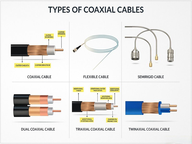
In the world of high-frequency communication, the smallest cable can make or break signal performance. Whether in an aircraft radar system, a medical imaging device, or a broadband network, coaxial cables are the invisible highways that carry precision data and RF energy. Yet for engineers and OEM buyers, the real challenge lies not in understanding what a coaxial cable is — but which type is right for their project.
A coaxial cable is a shielded electrical cable used to transmit high-frequency signals with minimal interference. The main types include RG-series, LMR, semi-rigid, micro coax, triaxial, and twinaxial cables, each designed for different power, frequency, and flexibility needs.
Choosing the correct type requires understanding impedance, attenuation, and flexibility — but more importantly, the environment where it will be used. One engineer’s RG6 may be another’s LMR-400. At Sino-conn, we’ve helped clients replace mismatched cables that caused 3dB signal loss and redesign assemblies to survive 120°C industrial environments.
If you’ve ever wondered whether to use RG6 or RG11, or whether 75Ω coax can substitute for 50Ω, this guide will walk you through every key concept — from structure to selection to customization. Let’s dive in.
What Is a Coaxial Cable and How Does It Work?
A coaxial cable consists of a central conductor, dielectric insulation, shielding, and an outer jacket. It transmits high-frequency electrical signals with low loss and excellent EMI resistance by maintaining a constant impedance. The inner conductor carries the signal, while the shield prevents external interference — making coaxial cables ideal for RF, video, and data communication applications.
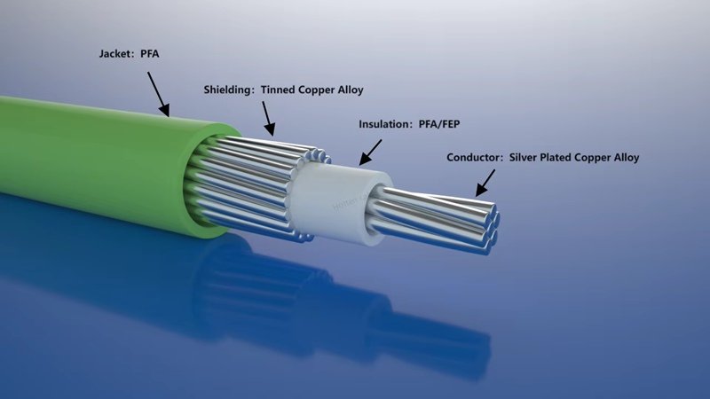
Core Structure of a Coaxial Cable
At its core, a coaxial cable is a symphony of precision engineering. The center conductor (usually copper or silver-plated copper) carries the signal. Surrounding it is a dielectric layer, controlling impedance and maintaining spacing. Outside that, the shield — made of braided copper or foil — blocks external electromagnetic noise. Finally, the outer jacket protects the assembly from mechanical or environmental damage.
How Coaxial Cables Transmit High-Frequency Signals
High-frequency RF signals are extremely sensitive to impedance mismatch. Coaxial cables preserve the signal by keeping the electromagnetic field confined between the inner conductor and shield. This design minimizes energy loss and reflection — a reason why even small variations in dielectric thickness or connector quality can cause performance degradation.
What Happens If You Use 75 Ohm Coax Instead of 50 Ohm?
Many engineers mistakenly interchange 50Ω and 75Ω cables. Doing so introduces mismatch loss — typically around 0.18 dB per connection, but it can exceed 1 dB in high-frequency systems.
- 50Ω cables are standard in RF and wireless communication because they balance power handling and low attenuation.
- 75Ω cables are optimized for signal clarity, making them ideal for video, broadcast, and data applications. Mixing them may still “work,” but it often results in return loss and degraded transmission quality in professional systems.
What Are the Main Types of Coaxial Cables?
Coaxial cables come in several main categories, each designed to meet specific performance requirements for signal transmission, power handling, and mechanical strength. The classification usually depends on the impedance (50Ω or 75Ω), flexibility, shielding structure, and application environment. Understanding these types helps engineers select the right cable for data communication, RF systems, instrumentation, or video networks.
In general, there are six major types widely used across industries: RG-series, LMR low-loss series, semi-rigid and semi-flex types, micro coax cables, and the less common but specialized triaxial and twinaxial cables.
How Many Types of Coaxial Cables Are There?
From a design standpoint, coaxial cables differ in conductor size, shielding method, dielectric materials, and flexibility. These variations directly impact performance parameters such as attenuation, impedance stability, and frequency capability.
The most recognized coaxial cable families include:
- RG-series (e.g., RG6, RG11, RG58, RG8) — traditional cables used in broadcast, RF, and general communication systems.
- LMR-series — modern low-loss alternatives to RG cables, known for superior performance and durability.
- Semi-rigid and semi-flex cables — specialized for aerospace and military applications where precision and shielding are critical.
- Micro coax cables — ultra-fine coax used in compact electronics and medical devices.
- Triaxial and twinaxial cables — advanced cables for balanced transmission and enhanced noise immunity.
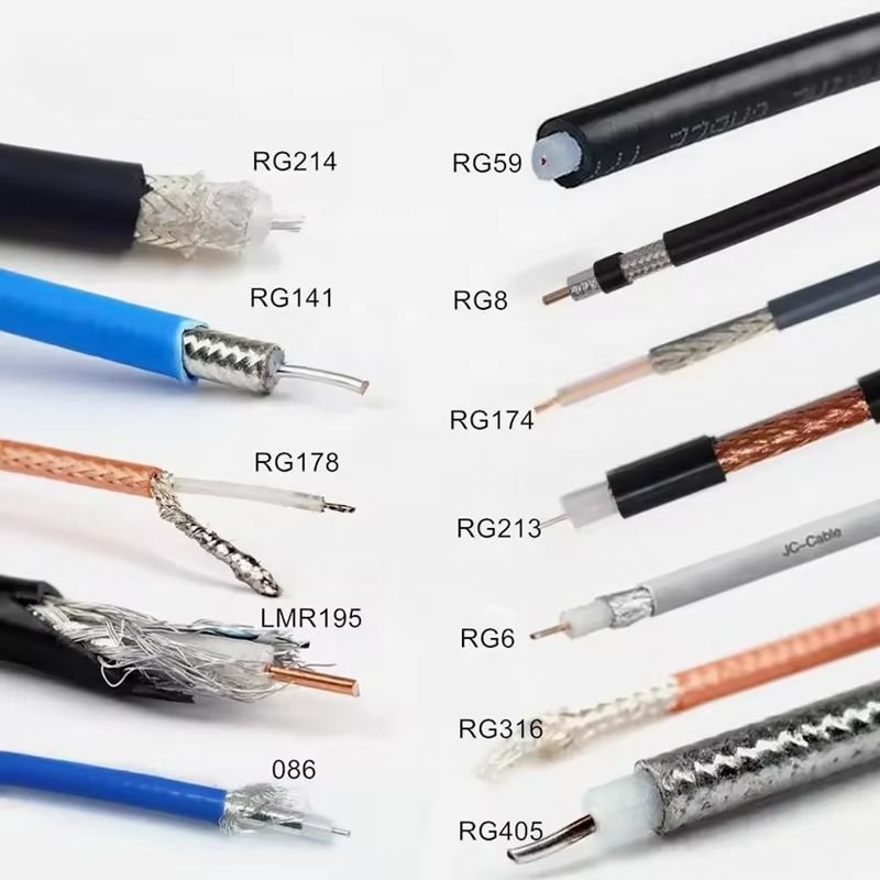
RG Series (RG6, RG11, RG58, RG8, etc.)
The RG (Radio Guide) family is the most familiar type and remains the industry’s standard for decades. It covers a wide range of frequencies and mechanical characteristics.
- RG6 – Common in household television, CCTV, and broadband setups; 75Ω impedance; affordable and flexible.
- RG11 – Designed for longer transmission distances with reduced signal loss; thicker and less flexible than RG6.
- RG58 – 50Ω cable popular for laboratory, instrumentation, and networking use; ideal for moderate-frequency RF signals.
- RG8 – A larger 50Ω cable for higher power RF or antenna connections; suitable for transmitters and base stations.
These cables differ mainly in attenuation (signal loss per length) and mechanical stiffness. RG11, for instance, can maintain a strong signal over longer distances but is harder to bend during installation.
What Is RG-8 and RG11 Coaxial Cable Used For?
- RG-8: Preferred in amateur radio, marine, or industrial RF systems requiring high power and low loss.
- RG-11: Typically used in long cable runs, such as broadband backbone lines, video distribution, or outdoor antennas.
| Cable Type | Impedance | Max Frequency | Typical Use Case | Loss @100ft (MHz) |
|---|---|---|---|---|
| RG6 | 75Ω | 3 GHz | TV, CCTV, Data | 5.65 dB @ 1 GHz |
| RG11 | 75Ω | 3 GHz | Long Cable Runs | 4.1 dB @ 1 GHz |
| RG8 | 50Ω | 2 GHz | RF & Power Systems | 2.9 dB @ 400 MHz |
| RG58 | 50Ω | 1 GHz | Networking, Radio | 6.4 dB @ 400 MHz |
This table shows how larger-diameter cables like RG11 and RG8 provide lower loss, while smaller ones (RG6, RG58) offer more flexibility and easier routing.
LMR Series
LMR cables are a modern, low-loss evolution of RG cables, developed for demanding RF, antenna, and communication applications.
They feature dual shielding (foil + braid) and gas-injected foam dielectric, which significantly lowers attenuation and improves flexibility.
- LMR-195 / LMR-240: Short-distance wireless or GPS connections where flexibility is important.
- LMR-400 / LMR-600: Long-range, high-power applications such as antennas, repeaters, and cellular base stations.
LMR cables maintain stable impedance across wide frequency ranges, often from DC to 6 GHz, and offer superior weather resistance, making them suitable for both indoor and outdoor systems. They are now a go-to choice for industrial and telecom engineers replacing aging RG lines.

Semi-Rigid and Semi-Flexible Coaxial Cables
For high-precision applications such as aerospace radar, test instrumentation, or military communication, semi-rigid coaxial cables are used.
They have a solid outer conductor (often copper or aluminum) instead of a braided shield, providing unmatched shielding effectiveness — sometimes up to 110 GHz frequency capability.
- Semi-rigid: Offers ultra-low loss, stable phase performance, and excellent EMI protection. However, it is not flexible once bent and requires forming tools.
- Semi-flex: Retains some flexibility while maintaining tight impedance control, making it easier to integrate into assemblies without sacrificing electrical performance.
These cables are often found in microwave modules, avionics, satellites, and RF test equipment, where precision and repeatability are essential.
Micro Coaxial Cables (I-PEX / U.FL / MHF)
Micro coaxial cables represent the miniaturization trend in modern electronics. With outer diameters as small as 0.81 mm, they enable high-speed signal transmission in space-constrained designs.
Applications include mobile devices, drones, cameras, sensors, laptops, and medical equipment — essentially any product that integrates high-frequency signals in compact layouts.
These cables often terminate in I-PEX, U.FL, or MHF connectors, which can operate at frequencies up to 6 GHz while maintaining consistent impedance and low reflection. Despite their size, micro coax cables still offer robust shielding to minimize crosstalk in dense PCBs.
Triaxial and Twinaxial Cables
Both triaxial (Triax) and twinaxial (Twinax) cables are designed for environments where noise isolation and signal balance are paramount.
- Triaxial cables include an extra shielding layer and are commonly used in broadcast cameras, laboratory instruments, and medical monitoring equipment, where enhanced isolation reduces ground loop interference.
- Twinaxial cables contain two inner conductors within a single shield, providing balanced signal transmission. They are used in high-speed data and digital communication systems, such as 10GBase-CX4 Ethernet and USB 3.x interconnects.
While more expensive and less flexible than standard coax, triaxial and twinaxial designs provide critical performance advantages in precision or noise-sensitive environments.
Summary Table — Comparing Coaxial Cable Families
| Cable Family | Typical Impedance | Frequency Range | Flexibility | Shielding Type | Typical Applications |
|---|---|---|---|---|---|
| RG Series | 50Ω / 75Ω | Up to 3 GHz | Moderate | Single / Double Braid | TV, RF, Networking |
| LMR Series | 50Ω | Up to 6 GHz | High | Foil + Braid | Antenna, Telecom, GPS |
| Semi-Rigid | 50Ω | Up to 110 GHz | Low | Solid Tube | Aerospace, Test Systems |
| Semi-Flex | 50Ω | Up to 40 GHz | Medium | Dense Braid | Instrumentation |
| Micro Coax | 50Ω / 75Ω | Up to 6 GHz | Very High | Foil + Braid | Mobile, Medical, Sensors |
| Triax / Twinax | 75Ω / 100Ω | Up to 10 GHz | Medium | Multi-Layer Shield | Broadcast, High-Speed Data |
The diversity of coaxial cable types reflects the diversity of their applications — from high-power RF systems and broadband networks to microelectronics and aerospace.
By understanding these families and their electrical and mechanical traits, engineers can better match cable specifications to performance goals.
Whether the priority is low attenuation, tight impedance, or miniature flexibility, each type serves a distinct role in modern signal transmission.
Which Coaxial Cable Type Should You Choose for Your Application?
Selecting the right coaxial cable type depends on several interrelated factors — impedance, signal frequency, distance, loss tolerance, and installation environment. No single cable fits every need; rather, each type performs best under specific electrical and mechanical conditions. Understanding these trade-offs allows engineers to design systems with stable performance and predictable results.
At its core, choosing a coaxial cable is about balancing three technical priorities:
- Electrical performance — how efficiently it carries the signal (loss, impedance, shielding).
- Mechanical flexibility and durability — how easily it can be routed or bent without degrading performance.
- Environmental endurance — how well it withstands temperature, moisture, vibration, and chemical exposure.
Key Selection Factors: Frequency, Loss, and Flexibility
Frequency Range:
Each coaxial cable type has a rated frequency bandwidth. Higher frequencies demand tighter manufacturing tolerances and better dielectric materials to reduce signal reflection.
For instance:
- RG58 (50Ω) performs well up to about 1 GHz, suitable for radio or short-range RF use.
- RG6 and RG11 (75Ω) support up to 3 GHz, common in video, CCTV, and satellite systems.
- LMR-400 extends to 6 GHz, ideal for wireless communication, cellular repeaters, and GPS.
- Semi-rigid coax can reach 40–110 GHz, used in radar or aerospace systems.
Signal Loss (Attenuation):
Signal attenuation increases with both frequency and cable length. Thicker cables with better shielding generally provide lower loss, but are less flexible.
A simple rule of thumb:
- For short distances (<10m) — use flexible cables like RG58 or LMR-240.
- For medium distances (10–50m) — use RG6 or LMR-400.
- For long runs (>50m) — use low-loss types like RG11 or LMR-600.
| Cable Type | Typical Use | Max Frequency | Attenuation (100 ft @ 1GHz) | Flexibility |
|---|---|---|---|---|
| RG58 | Radio, Networking | 1 GHz | ~11 dB | High |
| RG6 | Video, Data | 3 GHz | ~5.6 dB | High |
| RG11 | Long Video Runs | 3 GHz | ~4.1 dB | Medium |
| LMR-400 | Antenna, RF | 6 GHz | ~2.7 dB | Moderate |
| Semi-Rigid | Aerospace, Test | 40–110 GHz | <1.0 dB | Very Low |
Flexibility and Installation:
The routing environment determines how flexible your cable must be. In confined spaces like control cabinets or mobile devices, bend radius is critical.
- Micro coax and RG58 are easy to route in tight bends.
- LMR-400 offers moderate flexibility with strong shielding.
- Semi-rigid cables require pre-bending and forming tools.
Which Is Better — RG6 or RG11 Coaxial Cable?
This is one of the most common comparison points among engineers and installers. Both RG6 and RG11 share the same 75Ω impedance but differ in size, signal loss, and flexibility.
- RG6: Thinner, easier to install, ideal for short indoor connections like set-top boxes, modems, and security cameras.
- RG11: Thicker with lower attenuation, suited for long outdoor cable runs (over 300–600 feet) such as main feeds, base stations, or commercial signal backbones.

In summary:
- Use RG6 for indoor or short-distance applications requiring flexibility.
- Use RG11 for outdoor, long-distance, or higher frequency links where maintaining signal strength is essential.
| Feature | RG6 | RG11 |
|---|---|---|
| Impedance | 75Ω | 75Ω |
| Cable Diameter | ~6.9 mm | ~10.3 mm |
| Max Frequency | 3 GHz | 3 GHz |
| Signal Loss (100 ft @ 1GHz) | ~5.6 dB | ~4.1 dB |
| Typical Length | ≤ 300 ft | ≤ 600 ft |
| Installation | Flexible | Stiff / Outdoor |
| Applications | Indoor video, CCTV | Outdoor, long video or broadband lines |
Matching Impedance to System Requirements
Impedance — measured in ohms (Ω) — defines how current and voltage relate within the cable. Matching impedance between cable and equipment prevents signal reflections and power loss.
- 50Ω systems (RF, telecom, test setups) emphasize power handling and VSWR control.
- 75Ω systems (video, broadband, audio) prioritize signal clarity and minimal distortion.
Using a 75Ω cable on a 50Ω system (or vice versa) can cause reflections and standing waves. Although the equipment may still operate, long-term performance, bandwidth, and efficiency will degrade. Therefore, always confirm your system’s impedance rating before specifying cable type.
Environmental and Material Considerations
Environmental stresses often determine whether a cable performs reliably over time. Consider the following factors before final selection:
- Temperature Range – Standard PVC jackets perform well between -20°C and +80°C; high-temp FEP or TPE jackets can exceed 125°C for industrial and automotive systems.
- UV and Moisture Exposure – Outdoor installations need UV-stabilized and waterproof jackets. LMR cables often use polyethylene jackets for weather resistance.
- Chemical Resistance – For factory or oilfield environments, choose fluoropolymer jackets (FEP, PTFE) that resist oils and solvents.
- Fire and Safety Requirements – Medical and military systems often specify halogen-free (LSZH) or flame-retardant materials to meet safety standards.
- Mechanical Stress – In robotic or moving assemblies, choose cables with flexible stranded conductors and high flex-cycle ratings.
| Environmental Factor | Recommended Material | Notes |
|---|---|---|
| High Temperature | FEP, TPE | Up to 125°C continuous |
| UV / Outdoor | PE Jacket | Weather & UV resistant |
| Oil / Chemical | FEP, PTFE | Resistant to corrosion and solvents |
| Fire Safety | LSZH, FR-PVC | Low smoke, non-toxic |
| High Flex Movement | Stranded Conductor | Withstands bending and vibration |
Application-Based Cable Recommendations
Here’s a simplified reference guide matching coax types to real-world applications:
| Application | Recommended Cable | Impedance | Key Benefit |
|---|---|---|---|
| Indoor TV / CCTV | RG6 | 75Ω | Flexible, cost-effective |
| Outdoor or Long Cable Run | RG11 | 75Ω | Lower loss, long-distance |
| RF Testing / Communication | RG58 / LMR-240 | 50Ω | Compact, flexible |
| High-Power RF / Base Stations | LMR-400 / RG8 | 50Ω | High power, low loss |
| Aerospace / Radar / Lab Testing | Semi-Rigid | 50Ω | High precision, stable phase |
| Mobile Devices / Medical Sensors | Micro Coax | 50Ω / 75Ω | Miniature, light weight |
This type of mapping helps design engineers quickly narrow down their choices based on both technical and physical constraints.
Choosing a coaxial cable is not just about matching part numbers — it’s about engineering for performance consistency.
- For consumer video or broadband, a 75Ω RG6 or RG11 is sufficient.
- For RF and industrial communication, 50Ω LMR or RG cables deliver the right power balance.
- For precision or compact systems, micro or semi-rigid coax ensures stable, interference-free transmission.
By aligning electrical parameters with real-world installation needs, you can ensure signal reliability, lower maintenance costs, and longer product lifespan — regardless of whether the system operates in a laboratory, a factory floor, or an outdoor antenna array.
How Do Connectors Affect Coaxial Cable Performance?
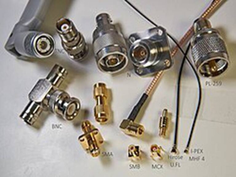
Connectors determine how efficiently a coaxial cable transfers signal. SMA, BNC, N, TNC, MCX, and MMCX are common, each with unique frequency limits, durability, and locking mechanisms that affect impedance matching and overall system reliability.
Common Connector Types (SMA, BNC, N, TNC, MCX, MMCX)
- SMA: up to 18 GHz, precision RF, test equipment
- BNC: quick connect/disconnect, used in CCTV and lab setups
- N-type: low-loss, waterproof, for outdoor antennas
- MCX/MMCX: miniature connectors for compact designs
Original vs Compatible Connectors
OEM customers often ask whether to use original or compatible connectors. Original ones guarantee spec compliance but come with higher prices and longer lead times. Sino-conn’s compatible versions maintain function and fit while offering faster delivery and cost efficiency — ideal for mid-volume OEMs.
Are Coaxial Cables Customizable?
Yes. Coaxial cables can be customized in length, shielding, impedance, jacket material, and connector type. Sino-conn provides fast drawings (within 30 minutes) and samples within 3 days, supporting full compliance with UL, ISO, and RoHS standards.
Available Customization Options
Customization goes far beyond length. Sino-conn tailors:
- Impedance: 50Ω, 75Ω, or others
- Shielding layers: single, double, or foil-braid hybrid
- Jacket materials: PVC, LSZH, TPE, FEP, etc.
- Connector pairing: SMA-to-BNC, N-to-MCX, or fully unique pinouts
Engineering Support and Drawings
Clients can submit a part number, specification, or even just a photo, and Sino-conn’s engineers generate CAD/PDF drawings within 30 minutes to 3 days for confirmation before production — ensuring accuracy and consistency.
Certifications and Compliance
All assemblies meet international standards — UL, ISO, RoHS, REACH, PFAS-free — and undergo three rounds of full inspection: in-process, completion, and pre-shipment testing.
Why OEMs and Engineers Choose Sino-conn for Custom Coaxial Cable Assemblies
Engineers choose Sino-conn for its rapid engineering support, flexibility in materials and connectors, certified quality, and competitive global pricing with short lead times.
Fast Prototyping and Engineering Expertise
Sino-conn offers samples within 3 days and mass production within 2 weeks, supporting projects that can’t wait for slow global supply chains.
Flexible Connector and Material Options
Both original-brand and compatible connectors are available, allowing OEMs to balance cost, availability, and performance requirements.
Full Quality Control and Inspection System
Every assembly undergoes 100% inspection — process checks, functional tests, and final verification — guaranteeing consistent performance and reliability.
Global Pricing Strategy and Lead Time Advantage
Sino-conn understands market variations — competitive pricing for Asia and Europe, and fast fulfillment for North America — without compromising quality.
How to Request a Custom Coaxial Cable Quote
What Information You Can Provide (Even Just a Photo)
Don’t worry if you lack full technical details. Many clients send just a photo or part number. Sino-conn’s engineers will identify the model, match connectors, and propose equivalent or improved solutions.
Our Quoting Process — From Drawing to Delivery
- Submit specs or images.
- Receive CAD/PDF drawings for confirmation.
- Approve the design.
- Receive samples within 3 days.
- Start production (2–4 weeks typical).
Sample and Mass Production Lead Times
- Prototype sample: 2–3 days (urgent)
- Batch production: 2–3 weeks
- No MOQ required — 1 piece accepted.

Conclusion
Choosing the right coaxial cable type is no longer guesswork. From RG6 and LMR-400 to micro and semi-rigid cables, every project demands precision in impedance, shielding, and build quality.
At Sino-conn, we don’t just manufacture cables — we engineer solutions. Whether you’re an OEM building RF modules or an engineer developing medical devices, our fast quoting, deep technical knowledge, and certified quality make us your trusted partner.
Ready to design your perfect coaxial cable?
Send us your drawing, photo, or requirement — and our team will deliver a tailored solution, from concept to production.