Skip to content
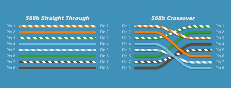
Ethernet cables look deceptively simple. To most people, a network cable is just a cable—plug it in, and data flows. But anyone who has ever faced a silent network port, a blinking LED that never turns green, or a device that simply refuses to communicate knows that Ethernet behavior can be far more nuanced. One of the most common—and surprisingly persistent—sources of confusion is the difference between straight through cables and crossover cables.
This confusion doesn’t only affect beginners. Purchasing teams often receive drawings that specify “RJ45 cable” without further detail. Engineers sometimes inherit legacy systems where cable behavior seems inconsistent. Even experienced technicians may wonder whether crossover cables still matter in an era of modern switches and Auto-MDI/MDIX. The result is uncertainty, wasted troubleshooting time, and occasionally, incorrect cable orders that delay projects.
A straight through cable connects different types of Ethernet devices, such as a PC to a switch, using the same wiring standard on both ends. A crossover cable connects similar devices, such as switch to switch, by crossing transmit and receive pairs. While many modern devices support Auto-MDI/MDIX and accept either cable type, straight through and crossover cables are still relevant in legacy systems, industrial networks, and custom Ethernet cable assemblies.
Years ago, a system integrator spent two days diagnosing what appeared to be a faulty industrial controller. The controller was fine—the issue was a crossover cable used where a straight through cable was required. That single detail delayed production and cost far more than the cable itself. Stories like this are why understanding the difference still matters today.
What Is a Straight Through Cable?
A straight through cable is an Ethernet cable wired identically on both ends, typically using T568A-to-T568A or T568B-to-T568B pinouts. It is designed to connect different types of network devices, such as computers to switches, switches to routers, or printers to network ports.
What pinout does a straight through cable use?
A straight through cable uses the same wiring standard on both connectors. The most common standards are T568A and T568B, defined by the ANSI/TIA-568 specification. In practice, T568B is more widely used in commercial installations, but functionally both standards behave the same as long as both ends match.
The key concept is consistency. Pins 1 through 8 on one end connect directly to the same numbered pins on the other end. This ensures that transmit and receive pairs align correctly when connecting different device types that already internally manage signal direction.
| Pin | T568B Color | Signal Pair |
|---|---|---|
| 1 | White/Orange | TX+ |
| 2 | Orange | TX− |
| 3 | White/Green | RX+ |
| 6 | Green | RX− |
This predictable wiring makes straight through cables the default choice in most Ethernet deployments.
What would you use a straight through cable for?
Straight through cables are used whenever two different network device roles communicate. Common examples include:
- PC or workstation to Ethernet switch
- Switch to router or firewall
- Network printer to switch
- IP camera to PoE switch
In these cases, one device transmits on pins that the other expects to receive on. The straight wiring preserves that relationship without modification. For this reason, straight through cables dominate office networks, data centers, and structured cabling systems.
Is straight through cable still used today?
Yes—straight through cables remain the most widely used Ethernet cable type. Even with Auto-MDI/MDIX, manufacturers and installers still default to straight through wiring for clarity, compatibility, and documentation. In regulated environments such as industrial automation or medical systems, predictable wiring is often preferred over relying on auto-negotiation features.
What Is a Crossover Cable?
A crossover cable is an Ethernet cable where the transmit and receive pairs are crossed between connectors, typically using T568A on one end and T568B on the other. It is designed to connect similar devices directly, such as two computers or two switches, without intermediate networking equipment.
How is a crossover cable wired?
In a crossover cable, the key difference is that the TX and RX pairs swap positions. Pins 1 and 2 on one end connect to pins 3 and 6 on the other end, and vice versa. This crossover allows two devices with the same internal pin configuration to communicate.
| Connection Type | End A | End B |
|---|---|---|
| Wiring Standard | T568A | T568B |
| TX/RX Pairs | Crossed | Crossed |
This wiring approach was essential before Ethernet devices gained the ability to automatically adjust signal direction.
What devices require crossover cables?
Traditionally, crossover cables were required for:
- PC to PC connections
- Switch to switch
- Hub to hub
- Router to router
These devices shared the same transmit and receive logic, so crossing the pairs externally was necessary. In labs, temporary setups, and legacy networks, crossover cables are still encountered.
Are crossover cables obsolete?
Not entirely. While many modern devices support Auto-MDI/MDIX, crossover cables remain relevant in legacy systems, cost-sensitive hardware, industrial controllers, and environments where auto-negotiation is disabled for stability. They also remain important in custom Ethernet cable assemblies where pin definitions must follow strict customer drawings.
What Is the Difference Between Straight Through and Crossover Cables?
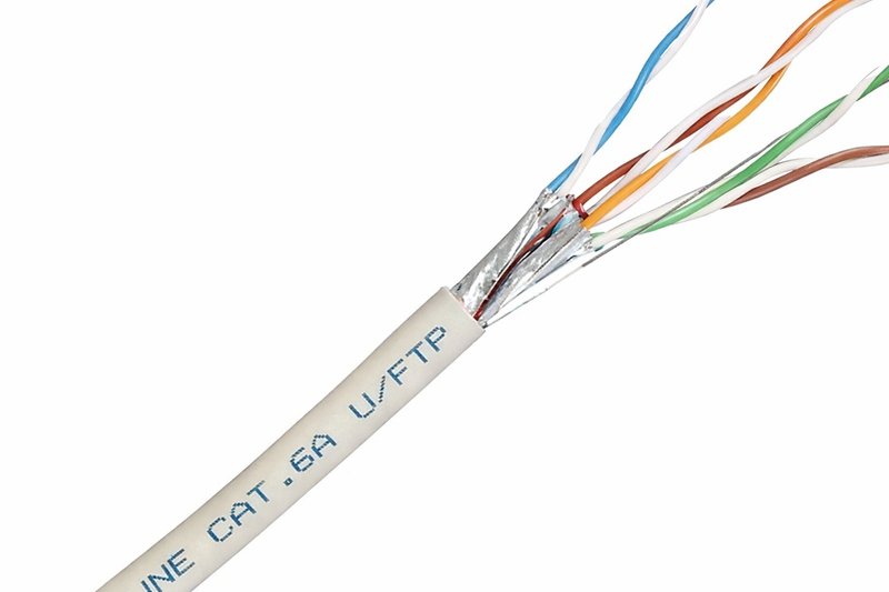
At a glance, straight through cables and crossover cables may look identical—both typically use RJ45 connectors and twisted-pair Ethernet cable. However, the fundamental difference lies in how the internal wire pairs are arranged and how network devices transmit and receive signals. This difference directly affects whether two devices can communicate reliably without additional network equipment.
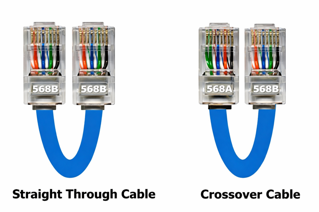
In simple terms, a straight through cable keeps the same pinout on both ends, while a crossover cable intentionally swaps the transmit (TX) and receive (RX) pairs. This wiring distinction determines which types of devices can be connected and under what conditions.
Straight Through vs Crossover: Pinout Differences
The most technical—and most important—difference between the two cable types is the pin assignment at each end of the cable.
- Straight through cable
- Uses the same wiring standard on both ends
- Common configurations: T568A–T568A or T568B–T568B
- Each pin number on one connector connects directly to the same pin number on the other connector
- Crossover cable
- Uses different wiring standards on each end
- Typically T568A on one end and T568B on the other
- Transmit and receive pairs (pins 1/2 and 3/6) are crossed
This crossing allows two devices with identical internal transmit/receive logic to communicate directly.
| Cable Type | End A Wiring | End B Wiring | TX/RX Pairs |
|---|---|---|---|
| Straight Through | T568A or T568B | Same as End A | Not crossed |
| Crossover | T568A | T568B | Crossed |
From a manufacturing and quality-control perspective, this difference also means that pinout definition must be clearly documented, especially for custom Ethernet cable assemblies.
Straight Through vs Crossover: Use Case Differences
The second major difference lies in application scenarios.
- Straight through cables are designed to connect different types of network devices, where one device transmits on pins that the other expects to receive on. Typical examples include:
- PC or workstation to Ethernet switch
- Switch to router or firewall
- IP camera to PoE switch
- Crossover cables are designed to connect similar devices directly, where both devices transmit and receive on the same pin pairs. Typical examples include:
- PC to PC
- Switch to switch
- Router to router
Although modern networks rely less on crossover cables than in the past, these use cases still exist in legacy systems, testing environments, and certain industrial networks.
Straight Through vs Crossover: Compatibility and Reliability
In modern Ethernet equipment, features such as Auto-MDI/MDIX allow many devices to automatically detect signal direction and internally correct for wiring differences. As a result, some devices can operate with either straight through or crossover cables.
However, this does not mean the two cable types are fully interchangeable:
- Not all devices support Auto-MDI/MDIX
- Some industrial or embedded systems disable auto-negotiation for stability
- Legacy hardware often expects a specific wiring configuration
In these situations, using the wrong cable type can lead to:
- No link establishment
- Intermittent communication
- Increased troubleshooting time
For this reason, explicitly choosing the correct cable type remains important, particularly in professional, industrial, or custom-designed network systems.
Why This Difference Still Matters in Custom Cable Projects
From a customer and supplier perspective, the difference between straight through and crossover cables is more than a theoretical concept—it directly affects design validation, production accuracy, and field performance.
In real-world projects:
- Customers may provide drawings with specific pin definitions
- Some applications require non-standard or mixed pinouts
- Cable assemblies must match system requirements exactly
Clear understanding and communication of these differences help avoid misinterpretation, reduce rework, and ensure that the final cable assembly performs as intended in its target environment.
Which Cable Should You Use: Straight Through or Crossover?
Choosing between a straight through cable and a crossover cable is not about preference—it is about matching the cable wiring to the way two devices communicate. While modern Ethernet technology has reduced the risk of using the “wrong” cable, the correct choice still matters in many professional environments, especially where system stability, compatibility, and documentation are critical.
As a general rule, straight through cables are used for most Ethernet connections, while crossover cables are used only in specific, well-defined scenarios. Understanding this distinction helps avoid unnecessary troubleshooting and ensures predictable network behavior.
Should I use straight through or crossover cable?
If there is any uncertainty, the safest starting point is a straight through cable. It is the industry default and works in the vast majority of Ethernet installations, including office networks, data centers, and commercial systems.
However, a crossover cable should be used when:
- Two similar devices are connected directly
- The devices do not support Auto-MDI/MDIX
- The system documentation or wiring diagram explicitly specifies a crossover connection
In professional projects, the decision is often dictated not by convenience, but by equipment design requirements and customer drawings.
Which cable is used for PC to switch?
A straight through cable is the correct choice when connecting a PC, workstation, or server to an Ethernet switch.
In this configuration:
- The PC and switch use different internal transmit/receive logic
- Straight through wiring aligns TX and RX pairs correctly without modification
This setup remains standard practice, even though most modern switches could technically accept a crossover cable. Using a straight through cable maintains consistency with network design conventions and simplifies installation and maintenance.
Which cable is used for switch to switch?
Historically, a crossover cable was required to connect two switches directly, because both devices transmitted and received on the same pin pairs. Crossing the TX and RX pairs at the cable level was necessary for communication.
Today, many modern switches support Auto-MDI/MDIX, allowing them to adapt internally and accept straight through cables. However:
- Not all switches support this feature
- Some industrial or managed switches disable it by default
- Legacy or cost-sensitive hardware may still require a crossover cable
For these reasons, it is always recommended to verify device specifications rather than rely on assumptions.
Decision Guide: Straight Through or Crossover?
The table below summarizes common connection scenarios and recommended cable types:
| Connection Scenario | Recommended Cable |
|---|---|
| PC to switch | Straight through |
| Switch to router | Straight through |
| PC to PC | Crossover |
| Switch to switch (legacy) | Crossover |
| Switch to switch (modern) | Straight through or crossover* |
| Industrial controller to controller | Depends on design |
- Always confirm Auto-MDI/MDIX support.
Why Cable Choice Still Matters in Professional and Custom Projects
In controlled or consumer environments, using the wrong cable often results in nothing more than a failed connection. In industrial, embedded, or custom Ethernet systems, the consequences can be more serious—ranging from unstable communication to extended downtime.
For custom cable assemblies:
- Pinout definitions must match system requirements exactly
- Assumptions about Auto-MDI/MDIX can lead to design errors
- Clear cable selection reduces installation risk and support costs
Selecting the correct cable type is therefore not just a technical detail, but part of a reliable system design process.
Practical Recommendation
For most standard Ethernet connections, use a straight through cable. Choose a crossover cable only when it is explicitly required by device design or project documentation. When in doubt, verifying the pinout and communication logic early in the project can prevent costly revisions later.
How Do Auto-MDI/MDIX and Modern Ethernet Devices Affect Cable Choice?
Auto-MDI/MDIX allows Ethernet devices to automatically detect and adjust signal direction, reducing dependence on crossover cables. However, not all devices support it, and some environments disable it intentionally.
Modern Ethernet simplifies installation, but assumptions can be risky. Industrial systems, legacy hardware, and custom designs often require explicit pin definitions. In these cases, understanding cable wiring remains essential.
How Are Straight Through and Crossover Cables Customized in Real Projects?
In real projects, straight through and crossover cables are customized by defining pinouts, cable length, jacket material, shielding, and connector type to match application, environment, and compliance requirements.
How is pinout defined for custom Ethernet cables?
Pinout definition is often the most critical factor. Customers may specify standard wiring or request non-standard mappings for proprietary equipment.
What cable specs matter for straight and crossover cables?
Important parameters include impedance, shielding (UTP, STP), jacket material, temperature rating, and EMI performance.
| Specification | Typical Range |
|---|---|
| Impedance | 100 Ω |
| Voltage | Low-voltage signal |
| Temperature | −20°C to +80°C (typical) |
| Shielding | UTP / FTP / STP |
Can cable length, jacket, and shielding be customized?
Yes. Length, overmolding, flexibility, flame rating, oil resistance, and UV resistance are frequently customized based on application.
Common Questions About Straight Through and Crossover Cables
Straight through and crossover cables differ in wiring, not speed. They are not inherently interchangeable, and using the wrong type can cause communication failure if devices lack Auto-MDI/MDIX.
Is a crossover cable faster than straight through?
No. Performance depends on cable category and quality, not wiring type.
Can I use a straight through cable instead of crossover?
Sometimes yes, sometimes no—device capability determines the outcome.
Are straight through and crossover cables interchangeable?
They are interchangeable only when devices support automatic signal correction.

Final Thoughts: Choosing the Right Cable—and the Right Partner
Understanding straight through vs crossover cables is not just academic. It affects network reliability, troubleshooting time, and procurement accuracy. In custom cable projects, small wiring decisions can have large operational consequences.
If you need custom Ethernet cable assemblies—whether straight through, crossover, or fully defined pinouts—Sino-Conn supports everything from 1-piece prototypes to volume production, with fast drawings, flexible connector sourcing, and full inspection control. Share your application, drawing, or even just a photo, and our engineering team can help translate it into a reliable cable solution.
When cable details matter, clarity is the strongest connection.