 Skip to content
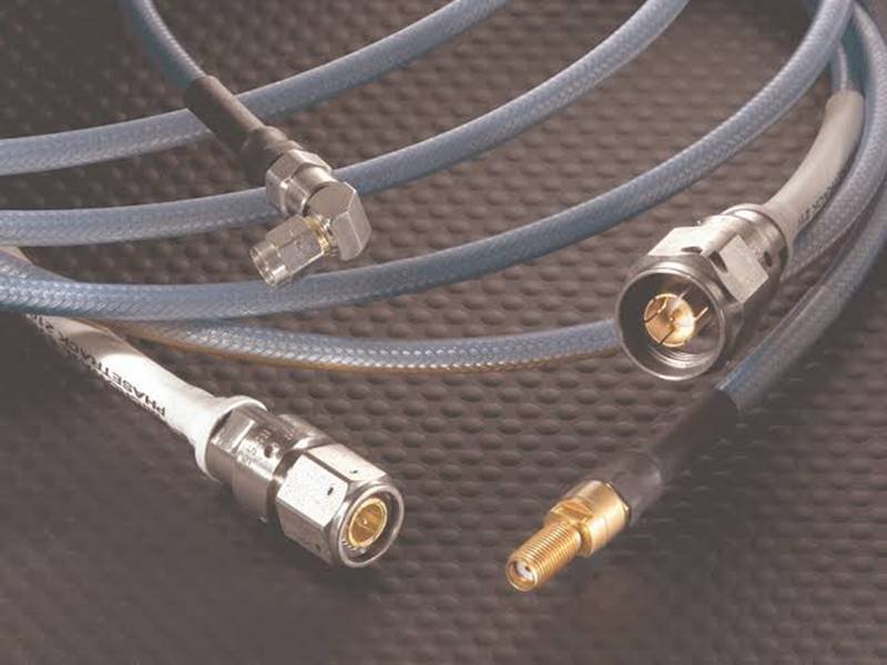
When engineers compare micro coax cables, the first questions usually involve AWG, outer diameter, connector pitch, shielding, impedance, or the number of signal channels. The dielectric – the thin material between the center conductor and outer shield – often receives less attention. That can be a costly oversight. Once a coaxial structure becomes smaller, faster, and more sensitive to dimensional variation, the dielectric is no longer just an insulating layer. Its electrical properties and physical stability become part of the transmission-line design, and they can influence whether an otherwise correct-looking assembly performs reliably after termination, bending, bundling, and installation.
Micro coax cables commonly use PTFE, low-density PTFE, ultra-low-density PTFE, FEP, PFA, and selected polyethylene-based dielectrics. The right choice depends on dielectric constant, dissipation factor, wall thickness, temperature capability, mechanical stability, processing method, and cable geometry. These factors influence characteristic impedance, capacitance, attenuation, propagation velocity, cable diameter, flexibility, and the consistency of signal performance in the finished production assembly over time.
The important point is that there is no universally best dielectric. Two cables can use the same connector, pass continuity testing, and look nearly identical on a workbench, yet behave differently once installed in a camera module, medical imaging system, robot joint, RF device, or compact display. Sometimes the difference is not the connector or conductor at all. It can begin with a few hundredths of a millimeter of dielectric geometry, a small change in material density, or compression that only appears after the cable is routed into the final device.

What Is a Micro Coax Dielectric?
The dielectric is the insulating material between the center conductor and shield of a micro coax cable. It maintains electrical separation while forming the geometry that helps determine impedance, capacitance, propagation velocity, and dielectric loss. In miniature coax, material type alone is not enough; dielectric diameter, wall thickness, concentricity, density, and resistance to deformation all contribute to stable electrical performance.
What Does the Dielectric Do?
A micro coax cable works as a controlled transmission structure rather than simply as a conductor wrapped in insulation. The center conductor carries the signal, the outer conductor or shield provides the return path and electromagnetic containment, and the dielectric holds a predictable physical relationship between them. That relationship controls how electric and magnetic fields are distributed along the line. For an ideal homogeneous coaxial structure, characteristic impedance can be approximated by Z0 ~= (60 / sqrt(er)) x ln(D/d), where er is relative permittivity, d is the center-conductor diameter, and D is the inner diameter of the outer conductor.
That equation is useful because it shows that impedance belongs to the material and geometry together. Changing dielectric constant without changing dimensions can move impedance. Changing dielectric thickness, conductor centering, or shield position can do the same. The dielectric also affects capacitance and propagation velocity, which matter in RF, clocked digital links, camera interfaces, and matched multi-channel assemblies. This is why a serious micro coax specification needs to consider AWG, dielectric diameter, shield construction, finished OD, target impedance, connector transition, bend path, and intended frequency or data rate as one connected system.
Is Dielectric the Same as Insulation?
A dielectric is an insulating material, but the two terms emphasize different engineering roles. Insulation describes the material’s ability to prevent unintended electrical contact or leakage between conductive elements. Dielectric describes how that insulating material behaves in an electric field, including its relative permittivity, dielectric loss, and contribution to transmission-line behavior. In a coaxial cable, the material surrounding the center conductor performs both roles, but its dielectric properties are especially important because it directly influences the electrical geometry of the line.
The outer jacket is different even when it is made from another electrically insulating polymer. Its primary responsibilities are usually mechanical and environmental protection, such as abrasion resistance, chemical resistance, flexibility, flame behavior, or handling protection. This distinction matters when a drawing says “PTFE cable” or “FEP insulated cable” without identifying which layer uses that polymer. A production-ready specification should distinguish dielectric material, dielectric wall thickness, outer jacket material, jacket thickness, temperature requirement, and any project-specific electrical target so purchasing and manufacturing teams are working from the same definition.
How Does Geometry Affect Impedance?
Micro coax impedance is created by the dimensional relationship between the center conductor, dielectric, and outer conductor, together with the dielectric constant of the insulating material. A nominal 50 ohm design therefore cannot be defined by saying “use PTFE” or “use FEP.” The cable maker must control conductor diameter, dielectric diameter, concentricity, shield position, and process variation so the completed cable stays within the intended impedance window over its usable length.
Several production and assembly conditions can disturb that balance even when the raw cable is correctly designed. Center-conductor eccentricity, dielectric diameter variation, over-tight bundling, clamping, overmold pressure, excessive stripping, shield fold-back length, or a very tight bend can alter the local field geometry. A continuity tester may still report a perfect connection, while TDR shows a local impedance discontinuity. In high-speed and RF assemblies, preserving the approved geometry through the connector transition is therefore just as important as choosing a good dielectric material at the cable-design stage.

Which Dielectric Materials Are Used?
Micro coax cables commonly use PTFE, lower-density PTFE structures, FEP, PFA, and polyethylene-based dielectrics. Fluoropolymers are valued for low dielectric loss, chemical resistance, and temperature capability, while PE-based materials can provide strong electrical efficiency where the thermal and environmental requirements are less severe. In practical production, the useful choice is the material that delivers the required properties inside a repeatable cable construction, not the material with the most impressive isolated datasheet number.
| Dielectric family | Typical relative permittivity* | Typical temperature class* | Common reason for selection |
| Solid PTFE | ~2.0-2.1 | Up to ~250-260 C | Low loss, RF performance, heat and chemical resistance |
| Low-density PTFE | ~1.4-1.8 | Construction dependent; polymer remains high-temperature | Lower effective Dk, lower loss, higher propagation velocity |
| FEP | ~2.0-2.1 | Around 200 C | Thin-wall processing and fluoropolymer performance |
| PFA | ~2.0-2.1 | Up to ~250-260 C | Thin-wall capability, heat resistance, melt processing |
| Solid PE | ~2.25-2.35 | Generally below fluoropolymers | Good electrical performance and cost efficiency |
| Foamed PE | Often ~1.3-1.8 effective Dk | Construction dependent | Lower effective permittivity and capacitance |
Representative industry ranges. Actual values depend on compound grade, density, frequency, processing, cable geometry, and test method. A finished assembly is limited by the lowest-rated relevant component, not by the dielectric polymer alone.
What Is PTFE?
PTFE, or polytetrafluoroethylene, is one of the most established dielectric materials in high-performance coaxial cable. Its appeal comes from a useful combination of relatively low dielectric constant, very low dielectric loss, strong chemical resistance, low moisture sensitivity, and high thermal capability. Solid PTFE is commonly treated as having a relative permittivity near 2.0 to 2.1 for engineering comparison, although the exact value depends on material grade, processing, frequency, density, and measurement method. That combination makes PTFE a frequent starting point for controlled-impedance RF, microwave, and other demanding signal constructions.
Still, PTFE should not be treated as a quality label that automatically guarantees a low-loss micro coax assembly. A 48 or 50 AWG center conductor has much higher resistance than the conductor used in a larger coax cable, and conductor loss can dominate the total attenuation budget at high frequency. Connector geometry, shield construction, cable length, and termination also matter. A useful engineering review therefore asks not only whether PTFE is used, but also what conductor size, dielectric diameter, shield geometry, finished OD, frequency range, insertion-loss target, and connector transition are part of the actual assembly.
What Is Low-Density PTFE?
Low-density PTFE uses the same general polymer family but introduces controlled air volume into the dielectric structure, reducing the effective dielectric constant because air has a relative permittivity close to 1. Depending on the construction, effective Dk may fall from roughly 2.0 for solid PTFE into the approximate 1.4 to 1.8 range. This can increase propagation velocity, reduce capacitance, reduce dielectric-loss contribution, and allow a different conductor-to-shield geometry for the same target impedance. In some designs, that geometry can make room for a larger center conductor, which may further reduce conductor loss.
The trade-off is mechanical. Reducing dielectric density can make a structure more sensitive to compression, crushing, tight bending, or dimensional change. In a micro coax cable, mechanical deformation quickly becomes an electrical issue because it alters the spacing between the center conductor and shield. Low-density PTFE is therefore especially useful when its electrical advantages justify tighter control of bend radius, handling, termination, cable clamping, and bundle pressure. The best design is not simply the lowest-density material available; it is the density and geometry that remain stable in the real installation.
When Are FEP and PFA Used?
FEP and PFA are fluoropolymers that are attractive when a micro coax cable needs a combination of strong electrical behavior, chemical resistance, elevated temperature capability, and practical thin-wall processing. FEP is often associated with approximately 200 C material classes, while PFA can reach roughly 250 to 260 C classes in suitable formulations. Their melt-processable nature can be an advantage when engineers need a thin, concentric dielectric wall around a very small conductor, particularly where cable OD and fine-pitch connector termination leave little room for dimensional variation.
The decision is rarely based on temperature alone. A thin-wall FEP or PFA construction may be preferred because it can be extruded and controlled more consistently at the required dimensions, even if another polymer offers a slightly better theoretical loss value. In miniature cable production, repeatable geometry can be more valuable than winning a comparison on one property. If a material supports cleaner stripping, better concentricity, controlled wall thickness, and a stable connector termination, the finished assembly can outperform a theoretically superior dielectric that is more difficult to manufacture within the required tolerance.
Is PE Used in Micro Coax?
Yes. Polyethylene and foamed polyethylene are widely used dielectric systems in communication and coaxial cable because they combine good electrical insulation with relatively low dielectric loss. Solid PE commonly has a relative permittivity around 2.25 to 2.35, while foamed structures can reduce the effective value substantially by incorporating air into the insulation. Depending on the foam ratio and process, effective Dk may fall into roughly the 1.3 to 1.8 range, which can reduce capacitance and support low-loss transmission-line geometries.
PE-based constructions can be attractive where electrical efficiency, cost, and stable extrusion are important, but they generally do not provide the same high-temperature capability as PTFE, PFA, or FEP. That can rule them out for certain high-temperature, harsh-environment, or specialized process conditions even when the electrical properties look appealing. The practical comparison should therefore include electrical loss, temperature, thin-wall capability, mechanical stability, flame or environmental requirements, connector termination, and supply consistency instead of treating PE and fluoropolymers as direct one-variable substitutes.
Which Dielectric Properties Matter?
The most important dielectric properties are relative permittivity, dissipation factor, wall thickness, concentricity, capacitance, temperature stability, and resistance to mechanical deformation. These properties interact rather than working independently. In micro coax, the real engineering question is whether the approved material and cable geometry can maintain impedance, loss, dimensions, and handling performance through extrusion, shielding, termination, bending, bundling, installation, and repeat production.
| Property | Common engineering unit | Practical importance in micro coax |
| Relative permittivity | Dk / er | Influences impedance, capacitance, conductor-to-shield geometry and propagation velocity |
| Dissipation factor | Df / tan delta | Contributes to dielectric loss, increasingly important as frequency rises |
| Wall thickness | mm | Controls geometry, OD, insulation margin and impedance |
| Concentricity | % or dimensional deviation | Determines uniform spacing between center conductor and shield |
| Capacitance | pF/m or pF/ft | Influences loading and is linked to geometry, Dk and impedance |
| Temperature | C | Affects dimensional stability, material behavior and long-term reliability |
| Characteristic impedance | ohm | Common examples include 50 ohm coax and project-specific controlled-impedance structures |
| Impedance tolerance | % | Many applications use approximately +/-5% to +/-10%; tighter limits require project-specific validation |
What Is Dielectric Constant?
Dielectric constant, also called relative permittivity or Dk, describes how strongly a material stores electric-field energy relative to vacuum. In coaxial cable it is one of the main variables behind characteristic impedance, capacitance, and propagation velocity. If the physical dimensions stay unchanged, increasing Dk generally increases capacitance and lowers characteristic impedance. In a simplified homogeneous dielectric, velocity factor is approximately 1 / sqrt(er), so an er of 2.0 corresponds to about 71% of the speed of light, 1.7 to about 77%, and 1.5 to about 82%.
Those values are useful for understanding the direction of change, but they are not finished-cable performance ratings. When a cable designer changes dielectric material, conductor diameter or dielectric thickness may also change to keep the target impedance constant. The resulting cable can therefore have different conductor loss, capacitance, flexibility, and OD even though both versions are nominally 50 ohm. Dk is best treated as a design input that helps determine the geometry, not as a simple ranking where the lowest number is automatically the best choice for every micro coax application.
What Is Dissipation Factor?
Dissipation factor, often written as Df or tan delta, describes the fraction of electrical energy dissipated in the dielectric during an alternating electric field cycle. Lower values are generally desirable as frequency and transmission length increase, which is one reason low-loss fluoropolymers and foamed dielectrics are widely used in RF and microwave cable. However, dielectric loss is only one part of total cable attenuation, and focusing on Df alone can lead to a poor design choice in very small coaxial structures.
Total insertion loss can include conductor resistance, skin effect, dielectric loss, shield loss, connector loss, transition discontinuities, and leakage caused by imperfect shielding. In ultra-fine micro coax, the very small center conductor can make conductor loss especially significant. A dielectric with an excellent Df value therefore does not guarantee the lowest finished-cable attenuation. A more useful comparison defines the frequency, cable length, conductor size, connector configuration, and installed condition, then evaluates the complete assembly rather than comparing resin values in isolation.
Does Wall Thickness Matter?
Dielectric wall thickness is one of the most important manufacturing dimensions in micro coax because it directly affects the spacing between the center conductor and shield. The smaller the cable becomes, the more important percentage variation becomes. A 0.02 mm dimensional change may sound insignificant in a conventional cable, but if a nominal wall is only 0.10 mm, the same change represents 20% of the nominal dimension. That scale helps explain why miniature coax performance depends heavily on extrusion control, conductor centering, and consistent downstream processing.
Engineers should review nominal dielectric diameter, minimum and maximum wall thickness, concentricity, longitudinal stability, thermal shrinkage, and possible deformation during shielding or assembly. The geometry can also change after raw cable production. Tight cable ties, overmold pressure, clamps, repeated bending, or excessive stripping can disturb the dielectric and shield relationship. High-frequency quality therefore depends on preserving the cable cross-section from the raw cable body through bundling and termination, rather than assuming a good nominal wall thickness remains unchanged after the assembly process.
How Important Is Temperature Rating?
Temperature rating matters, but it is often misapplied. A PTFE dielectric may have material capability approaching 250 to 260 C, while an FEP grade may commonly sit near the 200 C class. That does not mean the completed assembly can automatically operate at those temperatures. The connector, terminal, jacket, heat shrink, tape, adhesive, overmold, soldered or crimped termination, and any dynamic-flex requirement may introduce lower limits that determine the real operating range of the finished product.
Temperature also affects electrical stability, not just material survival. Repeated thermal cycling can create expansion and contraction between layers with different coefficients of thermal expansion. In phase-sensitive RF systems or tightly controlled impedance structures, the resulting dimensional movement may become measurable. A robust specification should therefore distinguish continuous operating temperature, storage temperature, installation temperature, short process exposure, thermal-cycle range, and whether the cable must bend while hot or cold. For high-speed or RF products, post-temperature validation may need to include impedance, insertion loss, or return loss rather than only visual inspection and continuity.
How Do PTFE, FEP, PFA, and PE Compare?
PTFE, FEP, PFA, and PE can all be strong dielectric materials, but they solve different engineering problems. PTFE is widely used for demanding RF and low-loss designs, FEP and PFA are useful where thin fluoropolymer processing and temperature capability matter, and PE can offer excellent electrical efficiency where the thermal environment allows it. The right comparison balances loss, geometry, temperature, flexibility, manufacturability, cost, and repeatability.
Which Material Has Lower Loss?
PTFE and lower-density PTFE are widely associated with low-loss coaxial construction, particularly as operating frequency moves into the GHz range. PE can also provide very low dielectric loss, which is why solid and foamed PE remain important in many communication and RF cable designs. The challenge is that a material-level comparison does not tell the whole story. A cable using a very low-loss dielectric but an extremely small center conductor may still have higher total attenuation than a slightly larger cable using a different dielectric because conductor loss becomes a major part of the budget.
The same problem appears at the connector. A technically excellent cable can lose much of its advantage if the termination introduces a large impedance discontinuity or excessive insertion loss. A realistic comparison should therefore specify frequency range, cable length, conductor size and plating, connector type, number of transitions, bend condition, and the allowable insertion-loss budget. For RF assemblies, VNA data is usually more meaningful than the phrase “low-loss dielectric.” For digital systems, system-level margin, eye quality, or functional stability may matter more than any single material property.
Which Material Handles Heat Better?
PTFE and PFA generally sit near the upper end of common fluoropolymer temperature capability, often around 250 to 260 C material classes, while FEP is commonly associated with about 200 C classes. Standard PE is usually lower, although exact limits vary significantly by formulation and cable construction. Even so, the maximum temperature on a material datasheet is only one part of the engineering decision because real applications expose cables to different combinations of time, temperature, mechanical load, and thermal cycling.
Continuous operation at 150 C, a brief 200 C assembly process, repeated cycling between -40 C and +125 C, and dynamic bending at -40 C are four very different requirements. A material can perform well in one condition and poorly in another because stiffness, dimensional stability, creep, or flex behavior changes with temperature. For high-temperature micro coax, the complete stack – conductor, dielectric, shield, jacket, termination, connector, and strain relief – needs to be reviewed together. The lowest-rated critical element determines the usable system limit, not the most temperature-resistant polymer in the assembly.
Which Material Supports Thin Walls and Flexibility?
FEP and PFA are frequently considered where very thin dielectric walls are needed because melt processing can support controlled miniature geometries. This can be valuable in camera modules, display assemblies, medical imaging devices, compact embedded electronics, and other applications where connector pitch and routing space leave little room for excess cable diameter. Low-density PTFE can provide excellent electrical behavior, but reduced-density structures may be more sensitive to compression, so the mechanical design around the cable becomes an important part of maintaining electrical performance.
Flexibility is also a property of the whole cable or bundle, not just the dielectric. Conductor diameter, conductor construction, individual coax OD, shield type, channel count, bundle arrangement, tape coverage, braid, outer jacket, and bend direction all contribute to stiffness. A single sub-millimeter coax can feel very flexible, while a bundle of dozens of identical channels may be significantly stiffer. For dynamic equipment, the relevant measurement is therefore the actual bend path and bundle behavior inside the product rather than a generic material description such as “flexible PTFE” or “flexible FEP.”
Which Material Is Easier to Process?
Processability often separates a theoretically attractive cable from a repeatable production cable. Micro coax manufacturing can require precise conductor centering, thin-wall dielectric extrusion, uniform shielding, controlled OD, accurate micro-stripping, shield fold-back, and fine-pitch termination. FEP and PFA are melt-processable fluoropolymers, which can be advantageous for controlled extrusion, while PTFE uses different processing methods but remains firmly established in high-performance coax manufacturing. The important question is whether the chosen construction can be produced consistently at the required dimensions and volume.
Downstream assembly matters just as much as extrusion. A dielectric that is difficult to strip cleanly can increase conductor nicks, exposed-length variation, or termination instability. A material that deforms too easily during heat exposure can disturb connector geometry, while a softer structure may need more controlled fixtures during clamping and overmolding. These details eventually become cost and lead-time factors because specialized stripping equipment, slower cycle time, tighter inspection, dedicated fixtures, and lower process yield all affect the finished assembly. Production decisions should therefore compare complete cable constructions, not resin price per kilogram.

How Does Dielectric Choice Affect Performance?
Dielectric choice affects impedance, capacitance, attenuation, propagation velocity, physical size, temperature stability, and sensitivity to bending or compression. These effects are connected: lower permittivity changes the geometry needed for a target impedance, while a softer or lower-density dielectric may respond differently to mechanical stress. Finished performance therefore comes from the complete conductor-dielectric-shield-termination system rather than from the dielectric material alone.
How Does Dielectric Affect Impedance?
Characteristic impedance is determined by both the dielectric constant and the physical relationship between the center conductor and outer conductor. That means two micro coax cables made from different dielectric materials can both be designed for 50 ohm operation by changing their conductor and dielectric dimensions. The flexibility is useful, but it also explains why changing dielectric material inside an existing design is not a simple substitution. Without redesign, impedance, capacitance, propagation velocity, attenuation, cable OD, and sometimes mechanical behavior can all change together.
Even a correctly designed raw cable does not guarantee assembly-level impedance. At the connector, the coax geometry is opened: the shield may be folded back, the dielectric stripped, and the center conductor routed into a contact. That creates a transition from controlled cable geometry to connector geometry. Excessive dielectric removal, long exposed conductor, uneven shield termination, or connector mismatch can create reflections even when the cable body measures correctly. For sensitive applications, TDR is valuable because it shows where the discontinuity occurs instead of reducing the entire assembly to one nominal impedance number.
How Does It Affect Attenuation?
Attenuation describes how much signal amplitude is lost as it travels through a cable, and it generally increases with both frequency and length. In micro coax, total attenuation is usually dominated by a combination of conductor loss and dielectric loss, with additional contribution from shielding and connector transitions. The dielectric affects attenuation directly through its dissipation factor, and indirectly because lower permittivity may allow a different geometry, such as a larger center conductor within a similar cable envelope for the same impedance.
This interaction becomes important when engineers push toward very fine AWG. As the center conductor becomes smaller, DC resistance rises, and at high frequency skin effect concentrates current near the conductor surface, increasing effective resistance. A “low-loss” dielectric cannot erase that conductor physics. Useful attenuation data therefore needs conditions: frequency, cable length, conductor size, connector configuration, and measurement reference plane. For RF systems, insertion loss should be reviewed alongside return loss or VSWR. For digital systems, the cable needs to fit into the complete channel budget rather than being evaluated in isolation.
How Do Propagation Speed and Cable Size Change?
Lower dielectric constant increases electromagnetic propagation velocity through the cable. Using the simplified relationship VF ~= 1 / sqrt(er), an er of 2.0 gives about 71% velocity factor, 1.7 gives about 77%, and 1.5 gives about 82%. This can matter in phase-sensitive RF links, matched channels, clock and data relationships, or systems where multiple micro coax paths need controlled timing. In a very short cable the absolute delay difference may be small, but the design implication becomes larger as channel length, frequency, or timing sensitivity increases.
Cable size is linked to the same equation. If a designer moves from a dielectric with er near 2.1 to a lower-permittivity material while keeping the same target impedance, the conductor-to-shield ratio can be redesigned. That may allow a larger conductor or a different dielectric thickness, potentially improving loss without increasing the overall envelope as much as expected. The trade-off is tolerance. Shrinking dielectric thickness reduces the dimensional margin available to extrusion, stripping, shielding, and bending, which is why a request to reduce cable OD by 20% should trigger an electrical and manufacturing review rather than a simple geometric scale-down.
Can Dielectric Variation Cause Signal Problems?
Yes. Dielectric variation can cause real signal-integrity problems even when the conductor remains electrically continuous. Diameter variation, conductor eccentricity, inconsistent material density, local compression, excessive bending, thermal deformation, overmold pressure, and termination differences can all change the effective electric-field geometry. The result may appear as TDR impedance excursions, inconsistent return loss, sample-to-sample insertion-loss variation, camera instability, display errors, or links that work when the cable is straight but become unreliable after installation.
A useful diagnostic approach is to look at where the electrical behavior changes. If a TDR discontinuity repeatedly appears near the connector, termination geometry should be examined first. If impedance moves along the cable body, dielectric dimensions, conductor centering, shield geometry, raw-cable consistency, and mechanical compression deserve attention. If the problem appears only after bending, compare measurements in straight and installed conditions. This kind of evidence-based troubleshooting is far more effective than changing the dielectric material blindly, because it identifies whether the root cause is material, geometry, termination, or mechanical routing.
How Do You Choose the Right Dielectric?
Choose the dielectric after defining the application, not before it. Start with signal type or frequency, impedance, cable length, allowable loss, OD, routing space, bend radius, temperature, connector, environmental conditions, and production needs. Then compare dielectric options inside realistic cable constructions. The best choice is the one that meets electrical requirements while remaining mechanically stable, manufacturable, testable, and repeatable from prototype through production.
| Application | Main dielectric priorities | Typical engineering checks |
| RF / microwave | Low Dk/Df, stable impedance | 50 ohm target, insertion loss, return loss, VSWR, frequency band |
| LVDS / eDP / MIPI | Geometry stability, low loss, compact OD | Differential impedance, skew, connector transition, channel consistency |
| Camera / imaging | Small OD, routing flexibility | Crosstalk, ground structure, image stability, bend path |
| Medical compact device | Miniaturization, thermal/material suitability | Bend radius, cleaning environment, connector size, system validation |
| Robot / moving device | Electrical stability under bending | Dynamic bend radius, fatigue, strain relief, bundle stiffness |
| High-temperature equipment | Thermal and dimensional stability | Cable, connector, jacket, termination and full-assembly temperature |
Which Material Fits High-Speed Digital Signals?
For LVDS, eDP, MIPI, high-speed camera, and similar links, dielectric selection should begin only after the interface architecture is understood. Useful starting data includes protocol or data rate, number of lanes, target impedance, maximum cable length, connector part number, routing envelope, allowed OD, bend requirement, and any shielding or grounding constraints. In many compact devices, micro coax is attractive because individual shielded signal paths can be arranged into dense multi-channel assemblies without giving up the routing flexibility needed around hinges, camera heads, display modules, or compact PCB stacks.
The lowest-Dk material is not automatically the best option. If a slightly different dielectric produces a more stable cable geometry, cleaner termination, easier routing, better connector transition, or more reliable supply while still meeting the signal budget, it may be the better production choice. SINO-CONN can review projects from drawings, connector part numbers, PCB interfaces, samples, or installation-space information, but the most useful development input is always a clear combination of electrical target and mechanical envelope. That allows material selection to be tied to the actual system rather than to a generic “high-speed” label.
Which Material Fits RF and Microwave?
RF and microwave applications place stronger emphasis on characteristic impedance, insertion loss, return loss, VSWR, phase behavior, and operating frequency. PTFE and lower-density PTFE are common starting points because their electrical characteristics are well suited to demanding coaxial structures, but the material cannot be assigned a frequency rating on its own. A cable that works well at 1 GHz, 6 GHz, 18 GHz, or 40 GHz faces very different loss and transition requirements even when every version is nominally 50 ohm.
A useful RF specification should include nominal impedance, operating frequency band, cable length, connector types, maximum insertion loss, and return-loss or VSWR target. When the design is phase sensitive, temperature-induced phase stability may also need to be considered. The connector launch, shield termination, conductor diameter, cable bend, and test reference plane all affect the result. For that reason, meaningful validation is normally performed on the finished assembly using VNA or another appropriate RF method rather than by approving a dielectric material certificate and assuming the assembled cable will behave the same way.
Which Material Fits Compact or High-Temperature Devices?
Very compact devices create some of the hardest dielectric trade-offs because electrical and mechanical margins become small at the same time. A thinner dielectric can reduce OD, but it also makes wall-thickness variation and conductor eccentricity more important. A lower-density dielectric can reduce electrical loss, but it may be more mechanically sensitive. A high-temperature fluoropolymer can survive a demanding thermal environment, yet the connector, heat shrink, adhesive, or overmold may still set a much lower limit for the complete assembly.
A practical design review should quantify the target individual coax OD, conductor AWG, connector pitch, routing envelope, minimum bend radius, cable length, operating and storage temperatures, signal type, and expected movement. Two devices that appear similar can therefore need different cable constructions. A camera module may mainly prioritize small OD and one-time flex routing, while an industrial imaging head may need the same footprint plus repeated motion and elevated temperature. Comparing two or three feasible constructions before freezing the design often gives engineering teams a much clearer view of performance, space, cost, and manufacturability.
How Should Dielectric Performance Be Validated?
Validation should match the actual failure risk. A low-speed miniature coax may need dimensional inspection, continuity, open and short detection, insulation checks, and mechanical fit verification. A controlled-impedance or high-frequency assembly may need more. A practical validation path can add TDR for impedance profile, VNA measurements for insertion loss and return loss, system-level camera or display testing, bend or routing validation, and environmental checks where temperature or repeated movement could change the cable geometry.
The goal is not to perform every available test. It is to identify the failure mode that would matter in the finished device and collect enough evidence to show that the approved construction remains stable under those conditions. In production, the validation plan should also distinguish type validation from routine inspection. Every assembly may receive continuity and open/short testing, while impedance, RF, environmental, or flex testing can be defined according to the product risk, customer specification, lot-control plan, and agreed acceptance criteria.
A well-chosen dielectric is therefore not simply the polymer with the lowest Dk, the highest temperature number, or the strongest marketing reputation. It is the material that allows the complete micro coax structure to achieve the required impedance, loss, diameter, bend behavior, thermal stability, and manufacturability with enough margin for repeat production. PTFE, low-density PTFE, FEP, PFA, and PE can all be appropriate when their properties are matched to the real electrical and mechanical problem instead of being selected in isolation.
For product teams developing a new micro coax assembly, the most useful next step is usually to freeze the application requirements before freezing the material. Connector interface, signal type or frequency, target impedance, cable length, installation space, bend path, temperature, shielding, and validation method should be reviewed together. Once those conditions are clear, SINO-CONN can evaluate a practical cable construction, prototype it, and move the approved geometry into controlled production without turning the dielectric decision into an unnecessary guessing exercise.
Frequently Asked Questions
What is the best dielectric material for micro coax cable?
There is no single best dielectric for every micro coax cable. PTFE and low-density PTFE are strong choices for low-loss and RF applications, FEP and PFA are useful when thin-wall fluoropolymer processing and high temperature capability are important, and PE can provide excellent electrical efficiency in suitable thermal environments. The correct choice depends on frequency, impedance, cable OD, bend radius, connector, temperature, mechanical loading, manufacturing process, and the performance margin required in the finished assembly.
Is PTFE better than FEP for micro coax?
PTFE often offers lower dielectric loss and very high temperature capability, which makes it attractive for demanding RF and microwave coaxial structures. FEP, however, is melt-processable and can be well suited to thin-wall miniature insulation, so it may offer manufacturing advantages in compact designs. The comparison should therefore include finished-cable attenuation, wall-thickness control, stripping and termination behavior, connector transition, operating temperature, bend requirements, and production repeatability rather than assuming PTFE is automatically better in every application.
How does dielectric constant affect micro coax impedance?
Dielectric constant changes the electrical relationship between the center conductor and shield. In an ideal coaxial structure, characteristic impedance depends on both relative permittivity and the ratio between outer- and inner-conductor dimensions. If dielectric constant increases while geometry stays the same, impedance generally decreases. Cable designers can compensate by changing conductor or dielectric dimensions, which is why two different materials can both be used to create nominally 50 ohm cables but may produce different OD, capacitance, attenuation, and mechanical behavior.
Does lower dielectric constant always mean lower cable loss?
No. Lower dielectric constant can support useful geometries and may help reduce dielectric-loss contribution, but total cable attenuation also depends heavily on conductor size, conductor material, shielding, frequency, connector transitions, and cable length. In very fine micro coax, conductor loss can be significant because the center conductor is small. A cable with a lower-Dk material can therefore have more total insertion loss than another construction if its conductor geometry or termination is less favorable. Finished-cable data at the required frequency is the better comparison.
What is the difference between solid PTFE and low-density PTFE dielectric?
Solid PTFE is a dense fluoropolymer dielectric with relative permittivity commonly near 2.0, while low-density PTFE introduces controlled air volume that reduces the effective dielectric constant, often into roughly the 1.4 to 1.8 range depending on construction. Lower effective Dk can increase propagation velocity and reduce dielectric-loss contribution, but lower-density structures may also be more sensitive to compression and tight bending. The choice therefore involves both electrical performance and the mechanical conditions the cable will experience during assembly and use.
How should micro coax dielectric performance be tested?
Testing should reflect the intended application. Baseline inspection normally includes dimensions, continuity, open/short detection, and insulation checks. Controlled-impedance products may add TDR, while RF assemblies can require VNA measurements for insertion loss, return loss, or VSWR. High-speed camera, display, or data assemblies may also need system-level functional testing. If the cable experiences repeated bending, temperature cycling, or a tightly constrained route, electrical measurements before and after the relevant mechanical or environmental condition can reveal problems that basic continuity testing will miss.



