Skip to content
Most wiring failures don’t happen because the wire is bad — they happen because the connector was used incorrectly.
In real-world projects, especially in OEM manufacturing, field installations, and prototype builds, wire connectors are often treated as “simple accessories.” Someone strips the wire, twists it together, pushes on a connector, and assumes the job is done. But months later, the system fails: signals drop, heat builds up, EMI interference appears, or the connection loosens under vibration. When engineers trace the issue back, the root cause is surprisingly small — improper connector selection or incorrect installation.
Wire connectors are not just mechanical joiners. They are electrical interfaces that directly affect current flow, signal integrity, safety compliance, and long-term reliability. The way a connector is chosen, prepared, crimped, locked, or sealed determines whether a system will operate flawlessly for years or fail unexpectedly in the field.
Wire connectors are components used to join electrical wires safely and reliably by ensuring stable electrical contact and mechanical retention. Proper use involves selecting the correct connector type, matching wire gauge, preparing conductors correctly, and applying the right crimping or locking method. Correctly used wire connectors improve safety, signal integrity, and long-term reliability across industrial, automotive, medical, and electronic applications.
In this guide, we will walk through how to use wire connectors correctly, step by step — not from a textbook perspective, but from the viewpoint of manufacturers, engineers, and OEM buyers who deal with real constraints like vibration, heat, compliance, cost, and production efficiency. Whether you are assembling prototypes, managing production lines, or sourcing custom cable assemblies, understanding wire connectors at this level will save you time, cost, and future failures.
What Are Wire Connectors and How Do They Work?
Wire connectors are devices used to join two or more electrical conductors securely, ensuring reliable electrical continuity, mechanical strength, and insulation protection. They work by applying pressure, crimping force, spring tension, or screw compression to create a low-resistance metal-to-metal contact between wires while preventing loosening, overheating, or short circuits. Wire connectors are essential in residential wiring, industrial control systems, electronic assemblies, and custom cable harnesses.
What Is the Core Function of a Wire Connector?
The primary function of a wire connector is to create a stable metal-to-metal contact between conductors. Electricity flows efficiently only when the contact resistance is low and consistent. Poor connections cause:
- Voltage drop
- Signal loss
- Heat buildup
- Arcing
- Long-term failure
Wire connectors achieve stability by forcing conductors into controlled contact using one or more of the following mechanisms:
- Mechanical compression
- Spring tension
- Crimp deformation
- Screw clamping
- Insulation displacement
In professional cable assemblies, connectors are designed so that the contact force remains constant over time, even under vibration, thermal cycling, or repeated mating.
How Do Wire Connectors Actually Make Electrical Contact?
Most wire connectors rely on controlled pressure to break through surface oxidation and maximize the conductive contact area.
Common contact mechanisms include:
- Crimped contact: The terminal barrel is permanently deformed around the conductor strands, creating a gas-tight joint. This is the most reliable method for OEM cable assemblies.
- Spring contact: A metal spring applies constant force to the conductor, compensating for thermal expansion and vibration.
- Screw compression: A screw clamps the conductor against a metal plate or terminal.
- IDC (Insulation Displacement Contact): Sharp metal blades cut through insulation and contact the conductor directly without stripping.
In high-quality crimped connections, the strands cold-weld together under pressure, reducing micro-movement and oxidation.
Why Is Mechanical Strength Just as Important as Electrical Performance?
Electrical performance alone is not enough. A connector must also survive real-world mechanical stress, including:
- Cable pulling
- Vibration
- Repeated movement
- Thermal expansion and contraction
If a connector loosens mechanically, electrical resistance increases—even if the wire is still “connected.”
This is why professional wire connectors are tested for:
- Pull-out force
- Vibration resistance
- Flex life
- Terminal retention strength
In industries like automotive, medical, and industrial automation, connectors must remain stable for 10–20 years of service.
How Do Wire Connectors Provide Insulation and Safety?
In addition to joining conductors, wire connectors must prevent accidental contact and short circuits.
This is achieved through:
- Insulating housings (nylon, PA66, PBT, PVC)
- Insulation support barrels that grip the wire jacket
- Heat-resistant plastics to prevent melting
- Flame-retardant materials meeting UL94 standards
Some connectors also provide strain relief, reducing stress at the conductor-to-terminal transition point—one of the most common failure zones.
Are All Wire Connectors the Same? Why Application Matters
Not all wire connectors are interchangeable. Choosing the wrong type can lead to failure even if installation looks correct.
Key factors that determine how a wire connector works in practice include:
- Wire gauge (AWG size)
- Stranded vs solid conductor
- Current and voltage rating
- Temperature range
- Environmental exposure (oil, moisture, UV, chemicals)
- Signal sensitivity (power vs data vs RF)
For example:
- A twist-on connector may work in residential wiring but is unacceptable in medical devices.
- A spring connector may be convenient but not suitable for high-vibration environments.
- A crimped terminal is preferred in OEM cable assemblies because it offers repeatable, inspectable quality.
How Do Wire Connectors Fit into Modern Cable Assemblies?
In professional cable assemblies, wire connectors are part of a complete system, including:
- Specified wire type and insulation
- Defined pin-out and circuit function
- Approved connector housing and terminals
- Controlled crimping process
- 100% electrical testing
Manufacturers like Sino-conn do not treat connectors as standalone components. Instead, they are engineered into the harness design to meet electrical, mechanical, and regulatory requirements simultaneously.
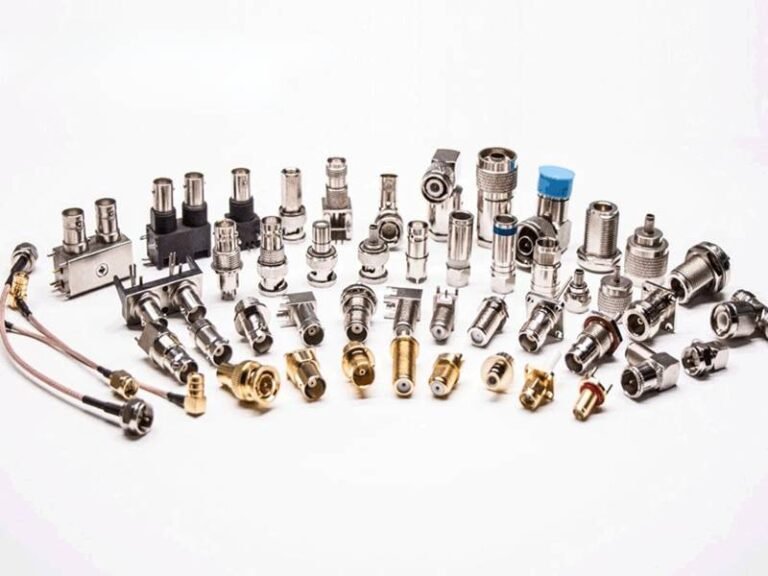
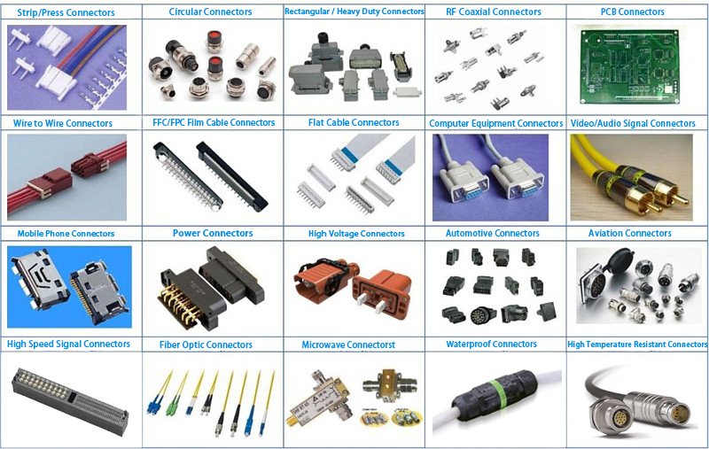
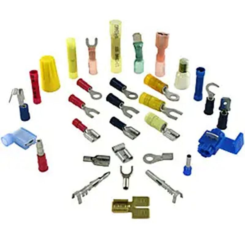
Which Types of Wire Connectors Are Commonly Used?
Common wire connectors include crimp connectors, wire nuts, terminal blocks, WAGO lever connectors, IDC connectors, solder connectors, butt splices, ring terminals, spade terminals, and plug-and-socket connectors. Each type is designed for specific wire gauges, current levels, installation methods, and environments, making correct selection essential for safety, durability, and electrical performance.
A Practical Classification of Wire Connector Types
Wire connectors come in many forms, each optimized for specific use cases. Below is a professional, application-driven breakdown of the most commonly used wire connector types in today’s electrical and electronic systems.
1. Crimp Connectors (Most Widely Used in OEM Manufacturing)
Crimp connectors are the industry standard for custom cable assemblies.
Common types:
- Butt connectors
- Ring terminals
- Spade (fork) terminals
- Pin terminals
How they work: A crimping tool compresses the metal barrel around the conductor, creating a gas-tight joint.
Advantages:
- Excellent vibration resistance
- Consistent electrical performance
- Suitable for automation
- No heat required
Typical applications:
- Automotive wiring harnesses
- Industrial machinery
- Power distribution cables
- Custom OEM cable assemblies
Sino-conn uses precision crimping with 100% pull-force and visual inspection to ensure reliability.
2. Wire Nuts (Twist-On Connectors)
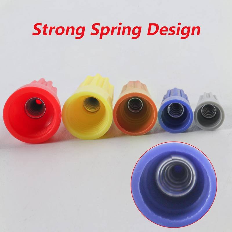
Wire nuts are commonly used in building and residential electrical wiring.
How they work: Wires are twisted together, then capped with a spring-loaded plastic connector.
Advantages:
- Simple installation
- Low cost
- No special tools required
Limitations:
- Not suitable for vibration environments
- Limited current range
- Not ideal for fine-strand or flexible wires
Rarely used in OEM cable assemblies but common in field wiring.
3. Terminal Blocks

Terminal blocks allow wires to be clamped or screwed into fixed positions.
Types:
- Screw terminal blocks
- Spring clamp terminal blocks
- DIN-rail terminal blocks
Advantages:
- Easy maintenance and reconfiguration
- Clear wire organization
- Suitable for control panels
Applications:
- Industrial control cabinets
- PLC systems
- Power distribution panels
4. Lever-Type Connectors (e.g., WAGO Connectors)

These connectors use internal springs and levers.
Advantages:
- Tool-free installation
- Reusable
- Consistent contact pressure
Best for:
- Lighting systems
- Building automation
- Field installations
Not commonly used for high-vibration OEM harnesses, but excellent for quick wiring.
5. Insulation Displacement Connectors (IDC)

IDCs connect wires without stripping insulation.
How they work: Metal blades cut through insulation and contact the conductor.
Advantages:
- Fast assembly
- Consistent connections
- Reduced labor
Applications:
- Ribbon cables
- Telecom wiring
- Data and signal cables
Used extensively in electronics and data communication systems.
6. Solder Connectors
Solder connectors create a permanent electrical bond.
Advantages:
- Low electrical resistance
- Compact connection
Disadvantages:
- Labor-intensive
- Heat-sensitive
- Poor vibration resistance if not strain-relieved
Often used in electronics repair or PCB connections rather than large-scale harnesses.
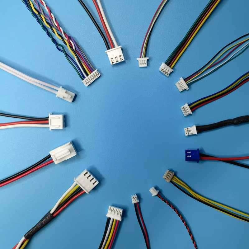
7. Plug-and-Socket (Wire-to-Wire / Wire-to-Board) Connectors

These connectors allow modular connections.
Examples:
- JST, Molex, TE, Hirose connectors
- Automotive multi-pin connectors
Advantages:
- Easy assembly and replacement
- Defined pin-outs
- Locking mechanisms available
Applications:
- Consumer electronics
- Medical devices
- Automotive modules
- Industrial equipment
Sino-conn supports both original-brand connectors and compatible alternatives, offering flexibility in cost and lead time.
Why Choosing the Right Wire Connector Matters
Selecting the wrong connector can lead to:
- Overheating
- Signal loss
- Intermittent failures
- Compliance issues
- Premature product failure
A professional supplier evaluates:
- Wire gauge (AWG)
- Conductor type
- Voltage/current
- Environment (heat, oil, vibration)
- Assembly method
- Regulatory requirements
This is why OEMs work with experienced cable assembly manufacturers like Sino-conn—to ensure the connector choice supports both performance and manufacturability.
How Do You Properly Install Wire Connectors Step by Step?
To install wire connectors correctly, match the connector to wire gauge and conductor type, strip to the specified length, insert fully, apply the correct tool or method (crimp, lever clamp, twist, solder), add strain relief or insulation support, and verify performance with a tug test plus continuity/resistance checks. For OEM reliability, follow a controlled process with defined strip length, crimp height, and 100% electrical testing to prevent intermittent failures.

Step 1 — How Do You Choose the Correct Connector Size and Rating?
Start with the wire: AWG size, stranded vs solid, insulation OD, and current/voltage. Then match connector specs: wire range, temperature rating, and environment rating. For example, a butt splice labeled for AWG 18–22 will not reliably hold AWG 24. If you’re in vibration, choose connectors designed for vibration resistance and use strain relief. If the customer only provides photos (common in trade/OEM sourcing), you must confirm the actual parameters: wire OD, core strands, connector series, pin count, and pin-out.
Step 2 — How Do You Strip and Prepare the Wire Without Damaging It?
Use the right stripping method and avoid nicking strands—especially in fine wires. Strip length must match connector requirements. Too short causes weak contact; too long exposes copper and invites shorts or corrosion. For stranded wire, keep strands together; don’t “fan” them out. For ferrules, don’t pre-twist excessively—insert cleanly and crimp. For shielded cables, keep shield termination consistent (drain wire placement, foil/braid control), because sloppy shield work creates EMI problems that look like “random device bugs.”
Step 3 — How Do You Install the Connector (Crimp / Lever / Wire Nut / Solder)?
- Crimp: Use the correct die and controlled pressure. Wrong tools create under-crimp (loose) or over-crimp (strand cut).
- Lever/Spring: Insert to the full depth, ensure correct strip length, confirm the clamp is fully closed.
- Wire Nut: Pre-twist if required by the type; ensure uniform capture of all conductors; no copper exposed.
- Solder: Avoid solder wicking too far back (creates a rigid stress riser). Use heat control and proper insulation recovery.
Step 4 — How Do You Add Strain Relief and Prevent Long-Term Failures?
A connector that survives day one can still fail in month six if there’s no strain relief. Add heat shrink, boots, overmold, cable clamp, or tie-down points to stop bending at the termination. This is crucial in robotics, medical devices, and any handheld equipment. The rule: don’t let movement concentrate at the connector barrel.
Step 5 — How Do You Verify the Connection Is Truly Reliable?
Do a tug test (a controlled pull) and electrical verification. For higher reliability, measure resistance under load or use continuity while flexing. For production/OEM harnesses, define acceptance criteria: strip length range, crimp height, pull-force minimum, and 100% continuity + short testing. This is where many suppliers differ: fast assembly is easy; repeatable quality is the hard part.
What Are the Most Common Wire Connector Mistakes and How Do You Avoid Them?
The most common wire connector mistakes include using the wrong connector type, incorrect wire gauge matching, poor stripping length, loose or over-tightened connections, ignoring insulation compatibility, and failing to test after installation. These errors can cause overheating, signal loss, short circuits, and premature failure. Avoiding them requires proper connector selection, correct installation techniques, adherence to electrical standards, and post-connection inspection and testing.
Understanding Wire Connector Failures and Prevention
Wire connectors look simple, but most electrical failures in real-world installations trace back to connector misuse rather than wire defects. In residential wiring, industrial control panels, automotive systems, and electronic assemblies, improper wire connector installation can lead to intermittent faults, overheating, EMI issues, arcing, and even fire hazards.
Below are the most frequent mistakes engineers, electricians, and DIY users make—and how to systematically avoid them.
Mistake 1 — Using the Wrong Connector Type for the Application
One of the most common errors is choosing a connector based on convenience rather than application requirements.
Typical Scenarios:
- Using twist-on wire nuts for vibration-prone environments
- Using IDC connectors where solid wire is required
- Using push-in connectors for high-current loads
- Using indoor connectors in outdoor or humid environments
Why This Fails:
Each connector is designed for specific:
- Current and voltage ratings
- Mechanical stress conditions
- Environmental exposure (heat, moisture, chemicals)
Using the wrong type can cause loosening, oxidation, or heat buildup.
How to Avoid It:
- Match the connector to application type (residential, industrial, automotive, electronics)
- Verify UL/IEC ratings
- Confirm suitability for vibration, temperature, and moisture
- When in doubt, consult connector datasheets or a cable assembly supplier like Sino-conn
Mistake 2 — Mismatching Wire Gauge and Connector Size
Wire connectors are designed for specific AWG ranges. Forcing wires outside that range is a silent failure waiting to happen.
Common Problems:
- Thin wire in oversized connector → loose contact
- Thick wire in undersized connector → damaged strands
- Mixed wire gauges improperly grouped
Consequences:
- Increased contact resistance
- Heat generation
- Voltage drop
- Intermittent signal failure
How to Avoid It:
- Always check the connector’s AWG specification
- Never exceed the maximum wire count per connector
- Use connectors explicitly rated for mixed gauges, if needed
- For OEM or electronics assemblies, specify wire gauge in the BOM and drawing
Mistake 3 — Incorrect Wire Stripping Length
Improper stripping is one of the most underestimated issues.
Common Errors:
- Over-stripping → exposed copper → short circuits
- Under-stripping → insulation inside contact → weak electrical connection
- Nicking conductor strands during stripping
Why It Happens:
- Using incorrect stripping tools
- Rushing installation
- Not following connector manufacturer guidelines
How to Avoid It:
- Use calibrated wire strippers
- Follow the connector’s recommended strip length (often 8–12 mm)
- Inspect stripped wires visually
- In precision assemblies, use laser or thermal stripping where applicable
Mistake 4 — Loose or Over-Tightened Connections
Both loose and over-tightened connectors cause problems, just in different ways.
Loose Connections Cause:
- Arcing
- Heat buildup
- Signal dropouts
- Intermittent failures
Over-Tightened Connections Cause:
- Crushed conductors
- Broken strands
- Reduced flex-life
- Hidden internal damage
How to Avoid It:
- Follow torque specifications for screw terminals
- Do a tug test after installation
- For spring or push-in connectors, ensure full insertion
- Avoid reusing single-use connectors
Mistake 5 — Ignoring Insulation and Material Compatibility
Not all connectors are compatible with all wire insulation types.
Risky Combinations:
- Soft silicone wire in sharp-edge connectors
- High-temperature wire with low-temperature plastic connectors
- Aluminum wire with copper-only connectors (without anti-oxidant)
Consequences:
- Insulation creep or cracking
- Chemical reactions
- Increased resistance over time
How to Avoid It:
- Match connector material to wire insulation (PVC, XLPE, PTFE, silicone)
- Use connectors rated for high temperature or chemical exposure if needed
- Verify compatibility in harsh environments (medical, automotive, industrial)
Mistake 6 — Skipping Post-Installation Testing
Many failures occur not because connectors were installed incorrectly—but because no one checked the result.
Commonly Skipped Tests:
- Continuity test
- Polarity check
- Insulation resistance test
- Load test
Why This Matters:
Some faults only appear:
- Under load
- After vibration
- During thermal expansion
How to Avoid It:
- Always test connections after installation
- Use a multimeter for continuity and resistance
- In OEM assemblies, perform 100% electrical testing
- Document test results for traceability
Mistake 7 — Reusing Old or Damaged Wire Connectors
Reusing connectors may save time—but increases failure risk.
Why Reuse Is Dangerous:
- Springs lose tension
- Threads wear out
- Plastic becomes brittle
- Internal oxidation may already exist
Best Practice:
- Treat most wire connectors as single-use components
- Replace connectors during maintenance or rewiring
- In critical systems, never reuse connectors
Mistake 8 — Ignoring Environmental and Mechanical Stress
Connectors that work in a static indoor environment may fail quickly when exposed to:
- Vibration
- Movement
- Moisture
- UV exposure
- Chemicals
How to Avoid It:
- Use vibration-resistant or locking connectors
- Add strain relief where movement exists
- Select IP-rated connectors for outdoor use
- Use UV-resistant materials in exposed areas
When Should You Choose Custom Wire Connectors or Assemblies?
You should choose custom wire connectors or assemblies when standard off-the-shelf connectors cannot meet your electrical, mechanical, environmental, or regulatory requirements. Custom solutions are essential for devices requiring specific pin-outs, precise lengths, unique connector combinations, EMI shielding, harsh-environment resistance, compact layouts, or industry compliance such as medical, automotive, aerospace, or industrial standards.

Below are the most common—and most important—situations where custom wire connectors or full cable assemblies become the correct engineering choice, not an optional upgrade.
When Standard Connectors Do Not Match Your Pin-Out or Wiring Logic
Most off-the-shelf connectors follow fixed pin configurations. However, real products often require:
- Non-standard pin sequencing
- Mixed power and signal pins in one housing
- Differential pairs with controlled spacing
- Ground-first or shield-first connections
- Mirrored or reversed pin-outs
- Dual-end connectors with different genders or series
Using standard connectors in these cases often leads to:
- Extra adapters
- Manual rewiring
- Higher assembly error rates
- Increased failure risk
Custom wire connector assemblies allow the pin-out to be engineered exactly to your circuit design, eliminating unnecessary interfaces and improving signal integrity.
When Cable Length, Routing, or Form Factor Is Critical
Standard connectors are usually paired with fixed cable lengths—or no cable at all. In contrast, many devices require:
- Exact cable lengths (±1–2 mm tolerance)
- Tight bend radius routing inside enclosures
- Flat, round, or hybrid cable structures
- Angled, low-profile, or overmolded exits
Examples include:
- Compact control boxes
- Medical instruments
- Robotics arms
- Automotive dashboards
Custom assemblies reduce:
- Excess cable clutter
- Mechanical stress on connectors
- Assembly time during production
This directly improves manufacturing efficiency and long-term reliability.
When Environmental Conditions Exceed Standard Ratings
Off-the-shelf connectors are usually designed for general indoor use. Custom connectors are essential when your product must operate in:
- High temperatures or thermal cycling
- Oil, fuel, or chemical exposure
- UV or outdoor environments
- High humidity or condensation
- Vibration and mechanical shock
Custom assemblies allow selection of:
- High-temperature wire insulation (XLPE, PTFE, FEP)
- Oil-resistant jackets
- Sealed or IP-rated connector housings
- Strain reliefs and overmolding
This is especially important in industrial, automotive, and outdoor equipment.
When EMI, Signal Integrity, or Electrical Performance Matters
For signal-sensitive applications, standard connectors alone are often not enough.
Custom wire assemblies can integrate:
- Twisted pairs
- Shielded cables
- Drain wires
- Braided or foil EMI shielding
- Grounded connector shells
These features are critical for:
- Sensors
- Communication devices
- Medical electronics
- Automation and control systems
Custom design ensures stable performance, reduced noise, and compliance with EMC requirements.
When Industry Certifications and Compliance Are Required
Many industries cannot legally use generic wiring solutions.
Custom assemblies are often required to meet:
- UL / CSA safety standards
- ISO requirements
- RoHS / REACH compliance
- PFAS-free or halogen-free material rules
- Medical or automotive regulatory frameworks
A custom supplier like Sino-conn can provide:
- Material traceability
- Test reports
- Drawings and documentation
- Consistent quality across production batches
When You Want to Reduce Total Cost, Not Just Part Price
While custom assemblies may appear more expensive at first glance, they often lower total system cost by:
- Reducing installation time
- Eliminating adapters and rework
- Lowering failure and warranty rates
- Improving assembly yield
For OEM factories, this often results in better margins and smoother production.
When You Need Fast Prototyping and Engineering Support
During R&D or product iteration, engineers often need:
- 1–10 sample pieces
- Quick drawing confirmation
- Engineering feedback on feasibility
Custom suppliers like Sino-conn offer:
- CAD → PDF drawings in as fast as 30 minutes
- Sample lead times of 2–3 days for urgent projects
- Design optimization support
Conclusion
Choosing the right wire connector or cable assembly supplier is no longer just about price. For modern OEMs, system integrators, and engineering teams, it’s about technical competence, response speed, customization capability, quality control, and long-term reliability.
Ready to Start? Let’s Build the Right Connection
If you are:
- Struggling with unreliable wire connections
- Developing a new product that needs custom connectors
- Looking to reduce cost without lowering quality
- Searching for a faster, more responsive cable assembly partner
Contact Sino-conn today.
Send us your drawing, part number, or even just a photo. Our team will respond quickly with technical advice, drawings, and a clear quotation—so you can move forward with confidence.
Sino-conn — Your Trusted Partner for Custom Wire Connectors and Cable Assemblies.