Skip to content
Replacing a ribbon cable connector seems like a minor repair task—until you try it. Anyone who has opened a laptop, medical device, or industrial control module has seen how fragile ribbon cables truly are: ultra-thin, tightly spaced conductors, sharp bend radii, and locking mechanisms that snap if handled even slightly wrong. Behind their simplicity lies a precision-engineered system, and replacing the connector requires an understanding of pitch, pin alignment, solder integrity, and mechanical locking—otherwise the device may fail intermittently or not power on at all.
In environments where downtime equals real cost—manufacturing lines, diagnostic equipment, aerospace modules—one damaged connector can halt an entire system. That’s why technicians and engineers look for the safest, most accurate method: the exact tools to use, how to avoid PCB pad damage, and how to verify that the replacement connector will perform reliably long-term.
To replace a ribbon cable connector, identify the connector type and pitch, safely remove the old connector using soldering or prying methods, clean and inspect the PCB pads, install the new connector with precise alignment, and reattach the ribbon cable while ensuring proper orientation and locking. Finally, verify signal continuity and perform functional tests to confirm a stable connection. This process requires careful handling, correct tools, and attention to detail.
Ribbon cable failures often happen silently: a cracked latch, a fatigued IDC tooth, or a lifted SMT pad invisible to the naked eye. I once worked with an OEM whose entire batch of handheld medical scanners failed because technicians replaced the ribbon cable connector with a 0.5 mm pitch model instead of 0.4 mm. The connectors looked identical. The units passed initial power tests but malfunctioned intermittently in the field. That single misjudgment forced a recall.
This guide not only prevents such mistakes—it helps you master every step with real-world clarity. Let’s dive in.
What Is a Ribbon Cable Connector and Why Does It Matter?
A ribbon cable connector is a compact interface that links flat ribbon cables—such as FFC, FPC, IDC, or flat ribbon—to a PCB or device. It provides high-density signal transmission in a lightweight, flexible form. These connectors matter because incorrect handling, pitch mismatch, or connector damage can lead to signal loss, boot failures, or device malfunction. Understanding their structure and function is essential for safe replacement and long-term reliability.
Understanding Ribbon Cable Connectors
Ribbon cable connectors are engineered for environments where many signals must pass through a small space. Laptops, automotive electronics, printers, robots, and medical imaging systems all rely on these connectors because they offer a combination of density, flexibility, and cost efficiency that round cables cannot match.
Yet this very advantage creates complexity: pitches can range from 0.3 mm to 2.54 mm, locking mechanisms vary widely, and even the slightest misalignment can cause cross-talk or open circuits. Below, we break down key concepts engineers must understand before replacing any connector.
Ribbon Cable Types (FFC, FPC, IDC, Flat Ribbon)
Ribbon cables are not one category—they include multiple types optimized for different purposes.
FFC (Flat Flexible Cable)
These are flat polymer-based cables with printed copper conductors. Common in displays, touchpads, automotive infotainment, and consumer electronics. Their connectors often use ZIF or LIF locking.
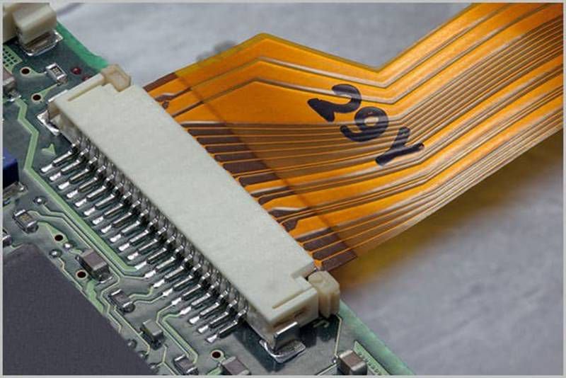
FPC (Flexible Printed Circuit)
Unlike FFCs, FPCs are laminated copper etched onto polyimide film, allowing tighter bends and smaller pitch spacing. They are widely used in medical instruments, cameras, drones, and compact electronics.
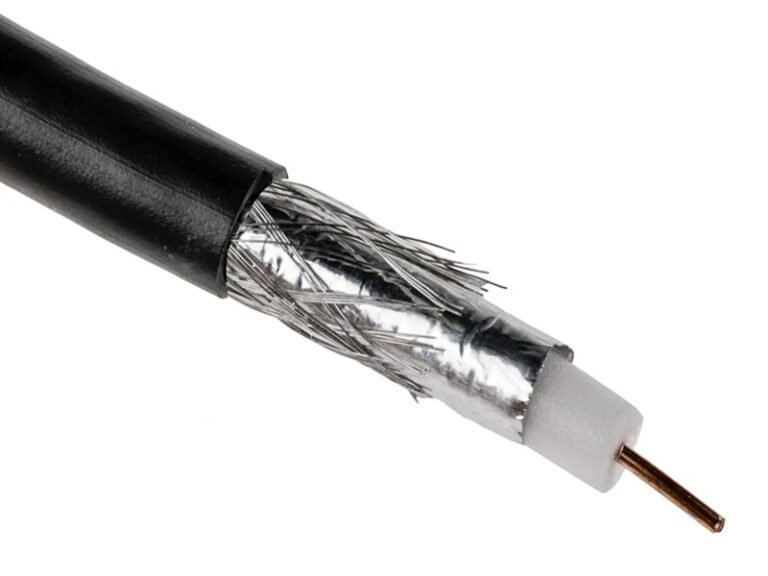
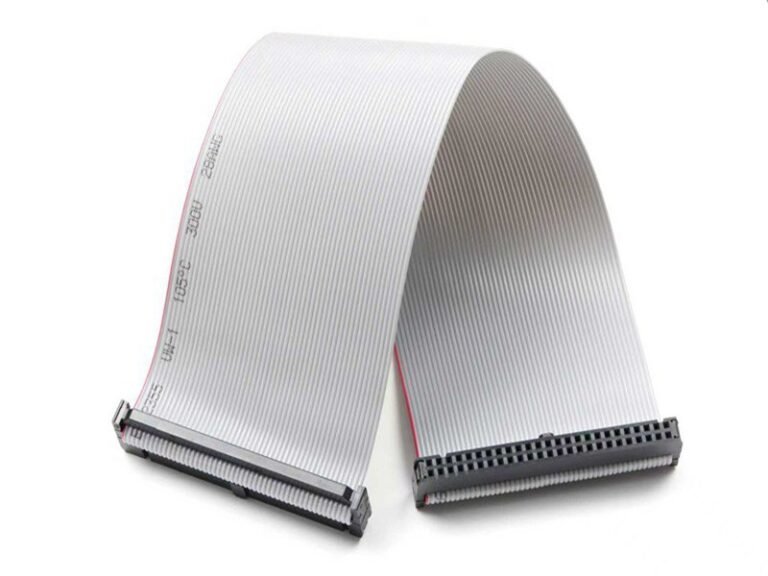
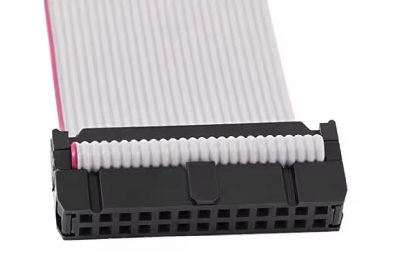
IDC Ribbon Cables
These use parallel copper conductors inside PVC insulation. They mate with IDC (insulation displacement) connectors that press the cable into metal blades—ideal for industrial devices and older PCs.
Flat Ribbon Cables
Classic ribbon-style conductors used with D-sub, sockets, and older logic systems. Their connectors often involve friction-fit or keyed housings.
Each type requires different removal pressure, alignment methods, and connector compatibility.
Connector Styles and Locking Mechanisms
Understanding locking mechanisms is essential because this affects how connectors must be removed or reattached.
ZIF (Zero Insertion Force)
Common for FFCs and FPCs. Requires the technician to lift or slide a latch before inserting the cable. Proper insertion depth is critical.
LIF (Low Insertion Force)
Similar to ZIF but uses friction rather than a locking bar. Requires more care during cable insertion.
Friction-fit Sockets
Older, simpler designs with no latch. Easy to remove but prone to wear.
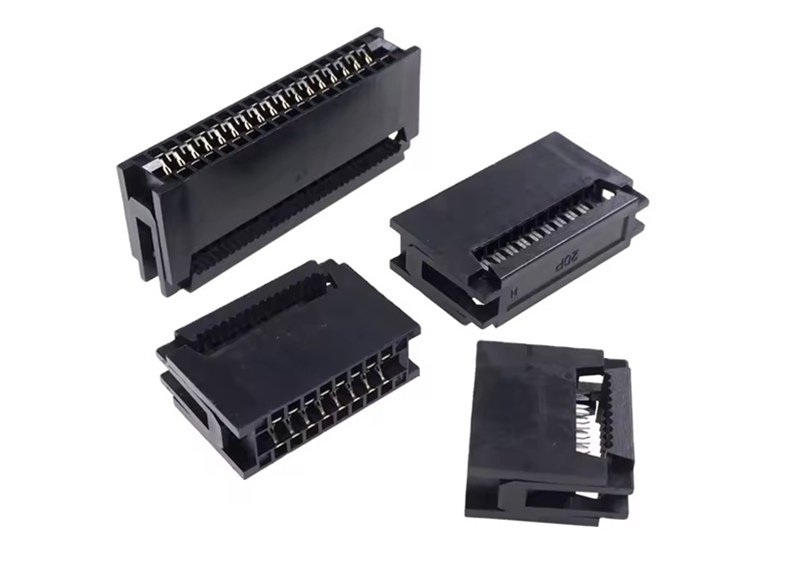
IDC Press-fit Connectors
Used for robust applications; require a crimp tool or press. Removal requires unclamping the housing.
These variations determine the tools and method needed for successful replacement.
Why Ribbon Cable Connectors Fail
Ribbon cable connectors often fail for mechanical or environmental reasons:
- Latch fatigue from repeated flexing
- Oxidation of contacts, especially in humid environments
- Connector housing cracks from improper removal
- Solder joint fatigue from vibration
- Pitch mismatch during replacement
- Bending strain on the cable near the terminals
In high-speed or EMI-sensitive systems, even a partially cracked connector can cause intermittent failures that technicians find extremely difficult to diagnose.
How to Identify the Correct Replacement Ribbon Cable Connector
To identify the correct ribbon cable connector, measure the pitch using calipers, confirm the total pin count, verify whether the connector is top-contact or bottom-contact, check the locking style, and compare the footprint with the existing PCB pads. If no datasheet is available, use photos, physical measurements, and cable markings to match the correct model. Accurate identification prevents alignment errors and ensures signal compatibility.
Identifying the Right Connector
Identifying a ribbon cable connector is often the hardest part of the entire replacement process—especially when customers only provide a blurry photo or a device with no manufacturer documentation. Many connectors look identical but differ in pitch, locking style, height, or even contact orientation. Using the wrong connector can cause boot failure, signal loss, or complete device malfunction.
Below is a systematic approach used by professional engineers, technicians, and suppliers like Sino-Conn.
Step 1 — Measure the Pitch and Pin Count (Most Critical Step)
Pitch is the distance from the center of one contact to the next.
Common pitches include 0.3 mm, 0.4 mm, 0.5 mm, 0.8 mm, 1.0 mm, 1.25 mm, 2.54 mm.
How to measure pitch accurately:
- Use calipers with 0.01 mm precision.
- Measure the distance across 10 pins; divide by 9.
- Compare with known pitch standards.
Why this matters:
A connector with a 0.5 mm pitch looks almost identical to a 0.4 mm one to the naked eye—but is completely incompatible.
Step 2 — Determine Contact Orientation
Ribbon cables insert either:
- Top-contact (metal contacts face up)
- Bottom-contact (metal contacts face down)
Inserting the cable into the wrong orientation connector causes:
- No connection
- Short circuits
- Burned contacts in some power cables
Always observe cable markings or test under a magnifier.
Step 3 — Identify the Locking Mechanism
Locking style reveals connector family and brand compatibility:
| Locking Type | Description | Common Use Cases |
|---|---|---|
| Flip-Lock ZIF | Hinged bar flips up/down | FFC/FPC in laptops, displays |
| Slide-Lock ZIF | Bar slides forward/back | Compact devices, cameras |
| Friction Fit | No latch, friction only | Legacy devices, industrial |
| IDC Press-Fit | Cable pressed into connector teeth | Automation, older PCs |
| Snap-Lock | Rigid latch on housing | Industrial ribbon cables |
Matching the locking mechanism is mandatory—otherwise the cable won’t secure properly.
Step 4 — Check Footprint and Height Profile
Even connectors with identical pitch may differ in:
- Height (low profile vs mid profile)
- Footprint length
- PCB pad spacing
- Solder pad shape
A mismatch of even 0.2 mm can misalign all pads.
Step 5 — If You Only Have Photos
This is where many customers struggle. Without specs, rely on:
- High-resolution pictures of the connector
- Visual comparison with known models
- Number of pins printed on the cable
- Cable’s pitch number (often printed like “0.5mm-26P”)
Suppliers like Sino-Conn solve this quickly with:
- 30-minute connector matching
- CAD drawings in under 3 days
- Comparative analysis for OEM/alternative brands
Step 6 — Consider Original vs Alternative Connectors
| Choice | Advantages | Disadvantages |
|---|---|---|
| Original (Brand Name) | High reliability, exact fit | High cost, long lead time, limited flexibility |
| Alternative (Equivalent) | Lower cost, faster delivery, flexible customization | Some customers may distrust non-brand parts |
For many industries—especially Europe and the U.S.—OEM-approved originals are preferred. But for fast prototyping or price-sensitive OEM factories, high-quality alternatives from Sino-Conn deliver the same performance with better availability.
What Tools and Materials Do You Need?
To replace a ribbon cable connector, you need precision tweezers, a plastic spudger, calipers, ESD protection, a fine-tip soldering iron, and a hot air rework station. For IDC cables, you need a crimping press or hand crimper. Additional materials include flux, solder wick, Kapton tape, alcohol wipes, and magnification tools. The right tools ensure safe connector removal, proper alignment, and reliable installation.
Understanding the Tools Needed
Ribbon cable connector replacement requires careful handling and precise tools. Attempting the job with the wrong equipment risks damaging PCB pads, melting the connector housing, or snapping the cable’s delicate copper contacts. Below is a complete engineering-level list of the tools needed, including when and why each is used.
Mechanical Handling Tools (Tweezers, Spudgers, Magnification)
Ribbon cable connectors are fragile. A cracked latch or bent pin often results from using metal screwdrivers instead of plastic tools.
Essential tools:
- Precision Tweezers: For lifting connectors during rework.
- Plastic Spudger: To prevent scratching or cracking latches.
- Fine-Tip Needle Probes: For checking alignment.
- Magnifying Lamp or Microscope: Vital for small-pitch connectors.
Failing to use magnification is a leading cause of misaligned solder joints.
Measurement Tools (Calipers, Pitch Gauges)
Accurate measurement determines correct connector selection and alignment.
Tools:
- Digital Calipers: Measure pitch and cable width.
- Pitch Gauge Cards: Useful for quick pitch verification.
- Cable Thickness Meter: Ensures proper ZIF compatibility.
Measurement accuracy is especially critical for 0.3–0.5 mm micro-pitch connectors.
Soldering and Rework Tools
For SMT-mounted ribbon connectors, these are mandatory:
| Tool | Purpose |
|---|---|
| Hot Air Rework Station | Even heating to remove/install connectors |
| Fine-Tip Soldering Iron | Precision for corner-tacking pads |
| Solder Wick / Braided Wick | Cleaning pads before installation |
| Flux Pen / Paste | Improves solder flow |
| Solder Paste (Lead-free or Leaded) | Reflow attachment |
Using excessive heat can warp the connector; using too little leads to cold joints.
Protective Tools
Protection is as important as precision.
Tools include:
- ESD Wrist Strap & Mat
- Kapton Tape for shielding heat-sensitive parts
- High-Purity Isopropyl Alcohol (IPA) to clean pads
- Latex or Nitrile Gloves to prevent skin oils on contacts
Without proper ESD control, FPC/FFC lines can be irreversibly damaged.
IDC Assembly Tools
IDC ribbon cables require crimp force, not heat.
Tools include:
- IDC Crimping Press (bench type)
- Hand IDC Crimpers for field work
- Press-Assist Clamp Tool
Incorrect crimp pressure leads to intermittent signals.

Optional Tools for High-Precision Work
For high-speed or medical devices:
- Thermal Camera for heat monitoring
- X-Ray Inspection for hidden solder joints
- Connector Seating Gauges
- Continuity Tester with Logging Function
High-reliability industries (military, medical) often require certification-level inspection.
How to Replace a Ribbon Cable Connector Step-by-Step
To replace a ribbon cable connector, first remove the old connector using hot air or prying tools depending on its type. Clean the PCB pads, align and install the new connector, apply solder or reflow heat as required, and verify proper locking. Insert the ribbon cable with correct orientation and secure the latch. Finally, test continuity, power on the device, and inspect for signal stability. Precision alignment and controlled heat are essential for success.
Full Replacement Procedure
Replacing a ribbon cable connector requires precision, patience, and an organized sequence. Even skilled technicians risk damaging PCB pads or misaligning micro-pitch connectors if they rush the process. Below is the professional workflow used in high-reliability industries such as medical electronics, industrial automation, and aerospace.
This section covers both soldered SMT connectors and IDC press-fit connectors, as well as proper testing after installation.
Step 1 — Safely Removing the Old Connector
Removal is the most sensitive stage.
For SMT FFC/FPC Connectors (ZIF, LIF, Friction Fit):
- Apply flux around the base.
- Preheat the area using a hot air station to reduce thermal shock.
- Heat the connector evenly at 280°C–320°C until solder liquefies.
- Using precision tweezers, lift the connector straight up.
- Avoid prying—this can rip PCB pads.
For IDC Ribbon Header Connectors:
- Desolder through-hole pins with a solder pump and wick.
- Gently rock the connector until free.
- Avoid bending pins—they may damage the plated-through holes.
Common failure during removal:
→ PCB pad delamination due to excessive heat or prying.
→ Connector housing melting from uneven heat.
Step 2 — Preparing Cable and PCB Pads
Once removed:
- Clean pads with solder wick.
- Wipe with IPA for a residue-free surface.
- Inspect pads under magnification for cracks.
- Repair minor pad damage with copper foil tape or solder bridges (only for low-speed circuits).
- Inspect the ribbon cable for tears, oxidation, or crease damage.
A clean, even surface ensures proper seating of the new connector.
Step 3 — Installing the New Connector
Installing SMT FFC/FPC Connectors:
- Align connector precisely with PCB pads—misalignment of even 0.1 mm matters.
- Tack two opposite corners with a fine-tip iron.
- Apply hot air at a controlled temperature to reflow the entire footprint.
- Use minimal solder to prevent bridges hidden under the connector body.
Installing IDC Connectors:
- Position ribbon cable over the pins.
- Press cable into the IDC slot using a press tool.
- Snap the cover shut evenly.
- Trim excess cable.
Good installation is measured by clean joints and a perfectly centered connector.
Step 4 — Reattaching the Ribbon Cable
This step depends on the connector type:
- ZIF: Lift latch → Insert cable fully → Lock latch.
- Slide-lock ZIF: Pull latch → Insert cable → Push latch back.
- LIF: Push cable in firmly.
- Friction-fit: Slide cable until fully seated.
Mistake to avoid:
Locking the cable at an angle—this causes half-connection and intermittent failures.
Step 5 — Testing & Validation
Test across 3 dimensions:
1. Electrical
- Continuity test per pin
- Multimeter resistance test
- High-speed signal integrity (for LVDS, MIPI, V-by-One)
2. Mechanical
- Light, even tug on cable
- Re-locking test
- Bend radius validation
3. Functional
- Power-on test
- Device I/O verification
- Camera/display test for visual systems
When Should You Replace, Repair, or Rebuild the Entire Cable Assembly?
Replace the connector if only the latch or housing is damaged. Replace the entire ribbon cable assembly when the cable is torn, creased, oxidized, or carries high-speed signals that demand perfect integrity. Rebuild or customize the assembly if the connector is discontinued, requires a special pin-out, or must meet specific environmental or EMI requirements. Proper evaluation ensures long-term reliability and reduces unexpected field failures.
Replacement vs Repair vs Rebuild
Choosing the right approach depends on the failure mode, device complexity, and operational environment. Many organizations waste time replacing connectors when the cable itself is damaged—or worse, they replace the cable when the connector was the real culprit.
Below is a structured decision process used by OEM engineers.
When You Should Replace Only the Connector
Connector-only replacement is appropriate when:
- The latch is broken
- The plastic housing is cracked
- The pins are bent or oxidized
- The connector suffered physical shock
- Pitch and cable remain compatible
This is common in laptops, industrial HMIs, printers, and medical display panels.
When You Should Replace the Entire Cable Assembly
Ribbon cables become unreliable when:
- The copper traces show cracks or wear
- High-speed lanes (LVDS, MIPI, HDMI) suffer from micro-damage
- The cable has permanent creases
- Contacts are worn from repeated insertions
- The cable insulation is heat-damaged
Replacing the whole assembly ensures stable signal transmission.
When You Should Rebuild or Customize the Assembly
This applies when connectors or cables are:
- Discontinued
- Impossible to source
- Cost-prohibitive in original brands
- Not available in required lengths
- Needed with custom shielding, high-temp materials, or special pin-outs
Sino-Conn specializes in this scenario because many customers lack datasheets and only have photos—yet still require exact replicas.
Table: Replacement vs Repair vs Rebuild Framework
| Scenario | Replace Connector | Replace Cable Assembly | Rebuild / Custom |
|---|---|---|---|
| Broken latch | ✔ | ||
| Cable creased | ✔ | ||
| Copper trace damaged | ✔ | ||
| Discontinued connector | ✔ | ||
| High EMI environment | ✔ | ||
| Incorrect cable length | ✔ | ||
| High-speed signal failure | ✔ | ✔ | |
| Wear from repeated insertion | ✔ |
How to Handle Custom or Hard-to-Find Ribbon Cable Connectors
For custom or hard-to-find ribbon cable connectors, use detailed measurements, photos, and pitch analysis to identify alternatives that match the original footprint and specifications. When no direct replacement exists, manufacturers can create custom assemblies with tailored pin-outs, materials, shielding, and connector equivalents. Fast CAD drawings, prototype samples, and flexible sourcing ensure compatibility when OEM parts are discontinued or unavailable.
Expert-Level Handling of Specialty Connectors
Many ribbon cable connectors are proprietary, discontinued, or application-specific. Devices from Japan, the EU, and legacy industrial equipment often use connectors no longer produced by the original manufacturer. Engineers face two options: hunt for rare parts online or build a custom replacement.
Working with a professional cable assembly supplier eliminates this problem entirely.
Identifying Hard-to-Find Connectors
Key strategies:
- Compare with Japanese, Taiwanese, and European connector families
- Analyze locking mechanism geometry
- Investigate pitch variations (0.3–2.54 mm)
- Identify contact plating and material requirements
- Match height and mounting style using reverse-engineering
Even obscure connectors can be mapped accurately with photos + caliper measurements.
Using Equivalent or Alternative Connectors
Equivalent connectors match the:
- Pitch
- Pin layout
- Footprint
- Mechanical properties
- Electrical characteristics
Benefits:
- Shorter lead times
- Lower cost
- Custom adjustments allowed
- Stable supply chain
Industries preferring originals: medical, aerospace
Industries accepting equivalents: consumer electronics, industrial OEMs, automation systems
Custom Assembly Solutions (Sino-Conn Advantage)
Typical customer needs include:
- Special cable lengths
- Pin-out remapping
- EMI shielding
- Chemical-resistant or halogen-free materials
- UV-resistant jackets
- High-temperature performance
- Fireproof / oil-proof designs
Sino-Conn delivers:
- Drawings within 30 minutes–3 days
- Samples in 2–3 days
- Bulk orders in 2–4 weeks
- No MOQ
- Multiple grade options (brand vs alternative)
This flexibility is crucial when original OEM parts cannot be sourced.
What Questions Should Engineers or Buyers Ask a Supplier?
Engineers should ask suppliers about connector pitch, pin-out accuracy, material certifications (UL, RoHS, REACH, ISO), customization capabilities, lead times for samples and bulk orders, and whether original or equivalent connectors are available. They should also confirm testing standards, drawing turnaround times, and environmental performance such as heat, oil, and UV resistance. These questions ensure compatibility and reliable long-term performance.
Supplier Evaluation Framework
Choosing the right ribbon cable assembly supplier is crucial for reliability and cost control. Many failures come not from incorrect installation, but from incorrect assumptions about cable materials, connector compatibility, or environmental durability. A good supplier significantly reduces these risks.
Key Technical Questions
- Can you verify the exact pitch and pin count?
- What are the cable’s electrical characteristics (impedance, voltage rating, EMI behavior)?
- Can you match or improve the original connector?
- Are drawing revisions included before production?
These questions prevent costly design mistakes early.
Material and Certification Questions
Ask whether the supplier can provide:
- UL approval
- ISO certification
- RoHS / REACH compliance
- PFAS-free materials
- Safety data for high-temp or corrosive environments
Industries like medical and defense require strict documentation.
Lead Time, Pricing, and Flexibility Questions
Critical for project planning:
- Sample lead time (Sino-Conn: 2–3 days for urgent orders)
- Bulk lead time (Sino-Conn: 2–4 weeks for urgent orders)
- MOQ requirements (Sino-Conn: No MOQ)
- Original vs alternative connector pricing
- Payment terms (common for OEM factories)
A flexible supplier accelerates prototyping and reduces risk.
Final Checklist Before Replacing a Ribbon Cable Connector
Before replacing a ribbon cable connector, verify pitch, pin count, and orientation; check the cable for damage; ensure PCB pads are clean and intact; confirm the new connector matches the original footprint; prepare all tools; practice ESD safety; and inspect locking mechanisms. After installation, perform continuity and functional testing. This checklist ensures reliable replacement and prevents hidden failures.
Full Replacement Checklist
A final checklist minimizes mistakes and ensures reliable results:
Pre-Installation
- Inspect connector and cable under magnification
- Verify contact orientation
- Confirm pitch with calipers
- Review PCB pad condition
- Cross-check footprint size
- Prepare ESD-safe work area
During Installation
- Align connector perfectly
- Use controlled heat
- Avoid excessive solder
- Confirm latch function
Post-Installation
- Run continuity tests
- Perform mechanical tug testing
- Validate function under load
- Inspect under magnification for bridges
This checklist is standard in professional repair labs.
Conclusion & Sino-Conn CTA
Ribbon cable connector replacement requires much more than basic soldering: it demands precise measurement, connector identification, proper tools, controlled heat, and extensive testing. Whether you are repairing a single device or developing a new OEM product, the reliability of your ribbon cable interface directly affects system performance.

If you need help identifying a connector from photos, verifying pitch, customizing pin-outs, or sourcing rare or discontinued connectors, Sino-Conn is ready to assist. With:
- 30-minute–3 day drawing turnaround
- 2–3 day urgent samples
- 2–4 week bulk delivery
- No MOQ
- Original or equivalent connector options
- Full certifications (UL, ISO, RoHS, REACH, PFAS, COC, COO)
- 100% inspection with 3-stage quality control
Sino-Conn can support your project from prototype to production.
Contact Sino-Conn today to request drawings, samples, or custom ribbon cable assemblies tailored to your exact needs.