Skip to content
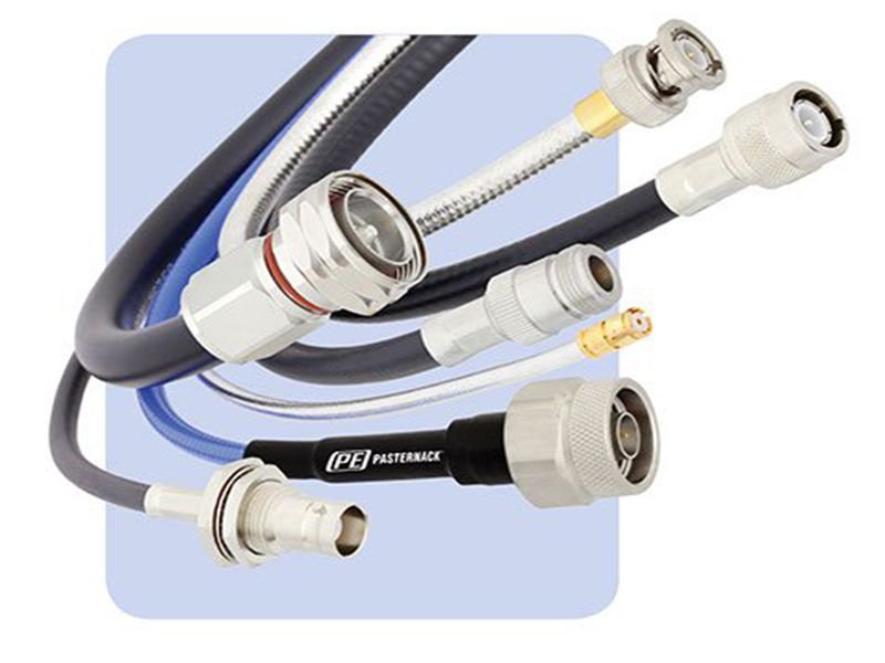
High-frequency signal transmission is not just about connecting two points—it’s about controlling energy. As frequencies rise into the MHz and GHz range, even small imperfections in cable structure, impedance mismatch, or shielding can cause measurable signal loss, reflection, or interference. This is why RF cable assemblies are engineered differently from standard electrical cables—they are precision transmission systems, not just conductors.
In simple terms, RF cable assemblies transmit high-frequency signals by confining electromagnetic energy within a controlled coaxial structure, maintaining consistent impedance, and minimizing signal loss through shielding and material optimization. These assemblies ensure that signals travel efficiently from source to destination without distortion, reflection, or interference, even in demanding environments.
In real-world projects, many customers come to Sino-Conn with only a photo or a rough idea of what they need. A telecom engineer once shared that replacing a poorly matched RF cable reduced signal loss by over 30% in their system—without changing any active components. That’s the hidden power of well-designed RF assemblies. Let’s break down how it all works.
What Are RF Cable Assemblies and Why Are They Used?
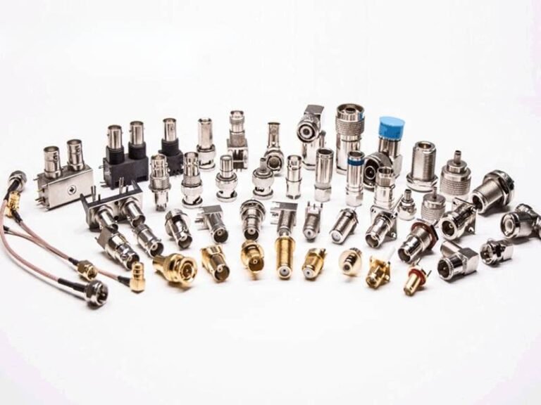
RF cable assemblies are purpose-built transmission components designed to carry high-frequency signals with controlled impedance, low loss, and strong resistance to interference. Unlike standard electrical wires, they are engineered systems where every layer—conductor, dielectric, shielding, and connectors—works together to ensure stable signal delivery. In practical terms, they are used whenever signal accuracy matters more than just electrical continuity, especially in applications operating from MHz up to multi-GHz ranges.

In real purchasing scenarios, many customers do not start with full specifications. Some only provide a model number, while others send a photo or describe the application. What they actually need is not just a cable, but a solution that ensures their system works reliably. That is why understanding what defines an RF cable assembly—and why it is necessary—directly affects project success, cost control, and long-term performance.
What Defines an RF Cable Assembly?
An RF cable assembly is a combination of a coaxial cable and RF connectors, designed to transmit signals with minimal reflection and attenuation. What makes it different from ordinary cables is the strict control of impedance and structure.
A typical RF cable assembly includes:
- Inner conductor (signal transmission path)
- Dielectric layer (controls spacing and impedance stability)
- Outer conductor/shield (blocks interference and contains the signal)
- Protective jacket (environmental protection)
- Connectors on both ends (interface with devices)

The most critical parameter is impedance, usually 50Ω or 75Ω. This value must remain consistent across the entire cable and connectors. Even a small deviation can cause signal reflection, which directly reduces system efficiency.
To make this more practical, here is how RF cables differ from standard cables:
| Parameter | Standard Cable | RF Cable Assembly |
|---|---|---|
| Impedance control | Not required | Strictly controlled |
| Frequency range | Low frequency | MHz to GHz |
| Signal loss sensitivity | Low | Very high |
| Shielding requirement | Minimal | Multi-layer |
| Application | Power, simple signals | Communication, RF systems |
In real projects, many issues come from misunderstanding this difference. For example, using a standard cable in an RF system can result in unstable signals, increased noise, or even system failure. That is why RF assemblies are treated as engineered components rather than generic products.
At Sino-Conn, customers often request detailed specifications including impedance tolerance, outer diameter (OD), shielding effectiveness, and material composition. Even when customers cannot provide full data, the engineering team can reconstruct the required structure based on application needs.
Which Industries Use RF Cable Assemblies?
RF cable assemblies are used across industries where signal accuracy, stability, and reliability are critical. Each industry has different priorities, which directly affect design and material selection.
Here are the main application sectors:
- Telecommunications infrastructure (base stations, antennas, 4G/5G systems)
- Medical equipment (imaging systems, monitoring devices)
- Aerospace and defense (radar, avionics, communication systems)
- Industrial automation (sensors, control systems)
- Consumer electronics (Wi-Fi routers, GPS modules)

Each industry has its own technical focus:
| Industry | Key Requirement | Typical Frequency Range |
|---|---|---|
| Telecom | Low attenuation, long-distance transmission | 1–6 GHz |
| Medical | Low noise, stable signal | 100 MHz–3 GHz |
| Military | High durability, extreme environment resistance | 1–18 GHz |
| Industrial | Flexibility, EMI resistance | 100 MHz–2 GHz |
| Consumer electronics | Cost efficiency, compact design | 500 MHz–2.5 GHz |
From actual customer interactions:
- Engineers usually provide detailed specifications and focus on performance
- OEM factories care about cost, consistency, and delivery time
- Traders often provide only part numbers or images and need technical support
For example, a European telecom customer may require halogen-free materials and strict impedance control, while a Southeast Asian OEM factory may prioritize cost efficiency and faster delivery. Sino-Conn adjusts solutions based on these differences to match both technical and commercial requirements.
Why Are RF Assemblies Critical for Signal Integrity?
At high frequencies, signals behave as electromagnetic waves rather than simple electrical currents. This means they are highly sensitive to external interference, internal structural changes, and impedance mismatches.
RF cable assemblies are designed to maintain signal integrity by controlling three main factors:
- Signal confinement The coaxial structure ensures that electromagnetic energy stays within the cable instead of leaking out.
- Impedance consistency A stable impedance prevents signal reflection, which can otherwise reduce transmission efficiency.
- Shielding effectiveness Multi-layer shielding blocks external electromagnetic interference (EMI), which is especially important in environments with multiple electronic devices.
The impact of poor design can be quantified:
| Issue | Typical Impact |
|---|---|
| Impedance mismatch | 10–30% signal reflection |
| Poor shielding | Increased noise, unstable signal |
| Low-quality materials | Higher attenuation over distance |
| Connector inconsistency | Signal discontinuity |
In practical terms, this means:
- A poorly designed RF cable can reduce signal strength by 20–40%
- System performance may degrade without obvious hardware failure
- Troubleshooting becomes difficult because the issue is not visible
One real example from Sino-Conn involved a customer experiencing intermittent signal loss in a communication system. After replacing the cable assembly with a properly matched impedance design, the signal stabilized immediately—without changing any other components.
How Do RF Cable Assemblies Transmit High Frequency Signals?
RF cable assemblies transmit high-frequency signals by guiding electromagnetic energy through a controlled coaxial structure, maintaining stable impedance, and minimizing losses caused by resistance, dielectric effects, and external interference. In practical terms, a well-designed RF assembly ensures that most of the signal power sent from the source actually reaches the destination without being reflected, absorbed, or distorted.
For customers, this is not just a theory issue—it directly affects system performance. In many real projects, signal problems are not caused by chips or antennas, but by improper cable assemblies. Understanding how RF transmission works helps avoid unnecessary redesign, cost increase, and long debugging cycles.
How Does Coaxial Structure Control Signal Flow?
The coaxial structure is the core reason RF cables can handle high-frequency signals reliably. Unlike standard wires, RF cables are designed to confine electromagnetic energy within a defined path.
A typical coaxial cable structure includes:
- Inner conductor (carries the signal)
- Dielectric layer (keeps spacing consistent and defines impedance)
- Outer conductor/shield (acts as ground and blocks interference)
- Outer jacket (protects against environment)
This structure creates a closed electromagnetic field between the inner and outer conductors. The signal does not travel randomly—it is guided along the cable in a stable and predictable way.
From a performance standpoint, this design provides three key benefits:
- Prevents signal radiation loss
- Reduces sensitivity to external noise
- Maintains consistent electrical characteristics
To make this clearer, compare the behavior:
| Structure Type | Signal Behavior | Result |
|---|---|---|
| Single wire | Signal radiates outward | High loss, unstable |
| Twisted pair | Partial control | Moderate interference |
| Coaxial cable | Fully confined | Stable, low loss |
In real applications, especially above 1 GHz, even small structural inconsistencies can affect performance. For example, uneven dielectric thickness or poor shielding contact can introduce impedance variation, leading to signal reflection.
What Role Does Impedance Matching Play?
Impedance matching is one of the most important factors in RF signal transmission. It determines how efficiently energy is transferred from one component to another.
In simple terms:
If impedance is not matched, part of the signal will bounce back instead of moving forward.
Most RF systems use:
- 50Ω (common in communication and testing systems)
- 75Ω (used in video and broadcasting systems)

The entire signal chain must maintain the same impedance:
- Cable
- Connectors
- Devices (antennas, modules, etc.)
Here is what happens when impedance is mismatched:
| Mismatch Level | Signal Reflection | Impact |
|---|---|---|
| <5% | Minimal | Acceptable |
| 5–10% | Moderate | Reduced efficiency |
| >10% | High | Significant signal loss |
This reflection is often measured using VSWR (Voltage Standing Wave Ratio). A higher VSWR means more signal is being reflected back.
Real-world example:
- A system with poor matching may lose 15–30% of signal power
- This can reduce communication range or data quality
- In extreme cases, it can damage sensitive RF components
Many customers are not aware of impedance issues at the beginning. They may focus on connector type or cable length, but ignore impedance consistency. Sino-Conn helps identify these risks early by reviewing specifications or samples before production.
How Does Shielding Reduce EMI Interference?
Shielding is what protects RF signals from external electromagnetic interference (EMI) and prevents signals from leaking out.
In environments with multiple electronic devices—such as industrial equipment, telecom systems, or medical devices—EMI is unavoidable. Without proper shielding, signals can become unstable or corrupted.
Common shielding structures include:
- Single braided copper shielding
- Aluminum foil shielding
- Combination of foil + braid
- Double or triple shielding for high-performance use
Shielding effectiveness can be quantified:
| Shield Type | EMI Reduction (dB) | Typical Use |
|---|---|---|
| Single braid | 40–60 dB | Basic applications |
| Foil + braid | 80–100 dB | Standard RF systems |
| Double shield | 90–110 dB | Industrial environments |
| Triple shield | 100+ dB | High-precision systems |
What this means in practice:
- Higher dB = better noise isolation
- Better shielding = more stable signal
For example, in a factory environment with heavy machinery, poor shielding can cause signal fluctuations or communication errors. Upgrading to double-shielded cables can significantly improve system stability.
Sino-Conn often recommends shielding upgrades when customers describe unstable signals, even if they initially focus on other components.
How Do Frequency and Skin Effect Influence Signal Transmission?
As frequency increases, signal behavior changes significantly due to the skin effect. This phenomenon causes current to flow mainly on the surface of the conductor rather than through its entire cross-section.
At higher frequencies:
- Effective resistance increases
- Signal loss increases
- Material quality becomes more important
Here is a simplified comparison:
| Frequency | Current Distribution | Impact |
|---|---|---|
| Low frequency | Uniform across conductor | Low loss |
| High frequency | Concentrated on surface | Higher loss |
This is why high-frequency RF cables often use:
- Silver-plated conductors (better surface conductivity)
- Smooth conductor surfaces (reduce resistance)
In addition, dielectric loss also increases with frequency. Materials like PTFE are preferred because they maintain stable electrical properties at higher frequencies.
From a customer perspective:
- At <1 GHz, standard materials may be sufficient
- At >3 GHz, material selection becomes critical
- At >6 GHz, precision design is required
Sino-Conn evaluates frequency requirements carefully and recommends materials accordingly, helping customers avoid performance issues that may not be obvious at lower frequencies.
How Do Assembly Quality and Manufacturing Precision Affect Performance?
Even with the right design, poor manufacturing can degrade RF performance. Assembly quality directly affects impedance consistency and signal continuity.
Critical factors include:
- Connector termination accuracy
- Crimping and soldering quality
- Cable stripping precision
- Shielding continuity
Common issues caused by poor assembly:
| Issue | Result |
|---|---|
| Improper crimping | Signal reflection |
| Loose shielding | Increased EMI |
| Inconsistent stripping | Impedance variation |
| Connector misalignment | Mechanical failure |
These problems are often difficult to detect visually but can significantly impact performance.
Sino-Conn addresses this with:
- Process inspection during production
- Final inspection after assembly
- Pre-shipment inspection before delivery
Which Factors Affect RF Signal Performance in Cable Assemblies?
RF signal performance in cable assemblies is influenced by a combination of material selection, cable length, frequency range, connector quality, and manufacturing precision. These factors determine how much signal is lost during transmission, how stable the connection remains over time, and whether the system performs consistently under real operating conditions.
For many customers, performance issues often appear as “unstable signal,” “reduced range,” or “unexpected noise.” In most cases, these problems are not caused by active components, but by small design or material mismatches inside the cable assembly. Understanding these factors early can prevent costly redesigns and repeated testing cycles.
How Do Materials Impact Signal Transmission?
Materials directly affect how efficiently signals travel through an RF cable. At high frequencies, even small differences in material properties can lead to noticeable performance changes.
The conductor material determines how easily current flows. Copper is widely used due to its good conductivity and cost balance. However, at higher frequencies, the skin effect causes current to concentrate on the surface of the conductor. This is why silver-plated copper is often used—it improves surface conductivity and reduces signal loss.
The dielectric material controls impedance and signal speed. Stable materials reduce variation and ensure consistent transmission.
Here is a practical comparison:
| Component | Material | Typical Use | Performance Impact |
|---|---|---|---|
| Conductor | Bare copper | General RF | Standard loss |
| Conductor | Silver-plated copper | High frequency (>3 GHz) | Lower attenuation |
| Dielectric | PE | Cost-sensitive applications | Moderate stability |
| Dielectric | PTFE | High-performance systems | Excellent stability |
| Shield | Single braid | Basic shielding | Moderate EMI protection |
| Shield | Foil + braid | Industrial/telecom | High EMI protection |
From real projects:
- Upgrading from PE to PTFE can reduce signal variation in high-frequency systems
- Using silver-plated conductors can improve performance in GHz-level applications
Environmental requirements also matter. Depending on usage, cables may need:
- UV resistance for outdoor installations
- Oil resistance for industrial machinery
- Flame retardant materials for safety compliance
- Halogen-free materials for European markets
Sino-Conn often helps customers choose materials based on actual working conditions, not just specifications on paper.
What Is the Effect of Frequency and Cable Length?
Frequency and cable length are the two most direct factors affecting signal loss. As frequency increases, attenuation rises. As cable length increases, total loss accumulates.
In simple terms:
Higher frequency + longer cable = more signal loss.
Here is a reference for attenuation trends:
| Frequency | Loss Level | Design Consideration |
|---|---|---|
| <500 MHz | Low | Standard materials acceptable |
| 1 GHz | Moderate | Improved shielding recommended |
| 3 GHz | High | Low-loss materials required |
| 6 GHz+ | Very high | Precision design critical |
Cable length amplifies this effect:
| Cable Length | Typical Impact |
|---|---|
| <1 meter | Minimal loss |
| 1–3 meters | Moderate loss |
| 3–10 meters | Significant attenuation |
| >10 meters | Requires optimization |
In real applications, customers often request longer cables for installation convenience. However, this can lead to performance issues.
Typical optimization strategies include:
- Reducing cable length where possible
- Using lower-loss cable types
- Increasing conductor quality
- Improving shielding
One real case involved a telecom system where reducing cable length from 8 meters to 5 meters improved signal strength by more than 20%, eliminating the need for additional signal amplification.
Sino-Conn engineers often review cable length during quotation and suggest practical adjustments to balance performance and usability.
How Do Connectors Influence Signal Performance?
Connectors are critical because they are the transition points where signals move between components. Even if the cable is high quality, poor connector performance can degrade the entire system.
Key factors include:
- Contact resistance
- Mechanical stability
- Frequency rating
- Impedance consistency
Here is a comparison of common connector types:
| Connector | Frequency Range | Application |
|---|---|---|
| SMA | Up to 18 GHz | High-frequency systems |
| BNC | Up to 4 GHz | General RF use |
| N-type | Up to 11 GHz | Outdoor/telecom |
| TNC | Up to 11 GHz | Vibration environments |

Another important consideration is the choice between original connectors and alternative connectors:
| Type | Advantage | Limitation |
|---|---|---|
| Original | Stable quality, brand reliability | Higher cost, longer lead time |
| Alternative | Lower cost, faster availability | Brand preference concerns |
From customer experience:
- Engineers tend to prefer original connectors for critical systems
- OEM factories often choose alternatives to reduce cost
- Traders focus on price competitiveness
Sino-Conn provides both options and helps customers select based on their priorities, ensuring compatibility and performance.
How Does Shielding Quality Affect EMI and Signal Stability?
Shielding protects signals from external electromagnetic interference (EMI) and prevents signal leakage. In environments with multiple electronic systems, shielding quality directly affects reliability.
Typical shielding structures:
- Single braid
- Foil + braid
- Double shielding
- Triple shielding
Performance comparison:
| Shield Structure | EMI Reduction | Application |
|---|---|---|
| Single braid | 40–60 dB | Basic systems |
| Foil + braid | 80–100 dB | Telecom, industrial |
| Double shield | 90–110 dB | High-noise environments |
| Triple shield | 100+ dB | Precision systems |
In real use:
- Poor shielding can cause signal fluctuation
- High EMI environments require stronger shielding
For example, in industrial automation systems, upgrading from single shielding to double shielding often reduces signal interference significantly.
Sino-Conn evaluates shielding requirements based on application environment, helping customers avoid under-design or over-cost solutions.
How Does Manufacturing Precision Affect RF Performance?
Manufacturing quality is often overlooked but has a direct impact on RF performance. Even with correct design and materials, poor assembly can introduce signal issues.
Critical manufacturing factors include:
- Connector termination accuracy
- Crimping consistency
- Cable stripping precision
- Shield continuity
Common problems caused by poor manufacturing:
| Issue | Result |
|---|---|
| Inconsistent crimping | Impedance variation |
| Poor soldering | Signal reflection |
| Damaged dielectric | Increased loss |
| Incomplete shielding | EMI leakage |
These issues may not be visible but can significantly affect performance.
Sino-Conn addresses this through:
- Full process inspection during production
- Final inspection after assembly
- Pre-shipment inspection
How Are RF Cable Assemblies Designed for Custom Applications?
RF cable assemblies for custom applications are designed by combining electrical requirements, mechanical constraints, and real-world usage conditions into a workable solution. In practice, most projects do not start with complete specifications. Some customers provide detailed drawings, while others only send a sample or even just a photo. The design process is about turning incomplete information into a reliable, manufacturable product that meets performance expectations.

From a customer perspective, the goal is simple: the cable must fit, connect correctly, and transmit signals without issues. But behind that, there are multiple design decisions that directly affect performance, cost, and lead time. A good design process reduces trial-and-error, shortens development cycles, and avoids unexpected problems during production.
What Parameters Must Be Defined in Specifications?
A clear specification is the foundation of any RF cable assembly project. The more accurate the input, the faster and more reliable the output. However, in real cases, many customers—especially traders or procurement teams—do not have full technical data.
A complete RF cable specification typically includes:
- Impedance (50Ω or 75Ω)
- Frequency range
- Cable length and tolerance
- Connector types on both ends
- Pinout definition (signal mapping)
- Cable outer diameter (OD)
- Shielding requirements (EMI level)
- Temperature range
- Flexibility and bending radius
- Environmental resistance (UV, oil, flame, halogen-free)
Here is a simplified structure:
| Category | Key Parameters | Why It Matters |
|---|---|---|
| Electrical | Impedance, frequency | Ensures signal integrity |
| Mechanical | Length, OD, flexibility | Ensures installation compatibility |
| Environmental | तापमान, UV, oil resistance | Ensures durability |
| Performance | Shielding, attenuation | Ensures stable operation |
In real projects, missing parameters are common. For example:
- A trader may only provide a connector model
- A buyer may send a picture of a cable
- An engineer may provide a partial drawing
Sino-Conn’s approach is to fill in the gaps. By analyzing the application, connector type, and usage environment, the engineering team defines the missing parameters and confirms them with the customer before production.
This reduces back-and-forth communication and helps customers move forward faster.
How Do Engineers Customize RF Cable Assemblies?
Customization is not just about adjusting length—it involves multiple dimensions that directly affect performance and usability.
Key customization areas include:
- Cable length (from a few centimeters to tens of meters)
- Connector type (SMA, BNC, N-type, TNC, etc.)
- Connector angle (straight, right-angle)
- Pinout configuration (how signals are routed)
- Cable material (PE, PTFE, low-loss materials)
- Shielding level (single, double, triple)
- Outer jacket (flexible, rugged, high-temperature resistant)
Here is how different customization choices affect the final product:
| Custom Option | Practical Impact |
|---|---|
| Length change | Affects signal attenuation |
| Connector change | Affects compatibility with devices |
| Material upgrade | Improves high-frequency performance |
| Shielding upgrade | Reduces EMI interference |
| Structure adjustment | Improves installation convenience |
In real customer scenarios:
- Engineers often request specific impedance and connector combinations
- OEM factories prioritize cost-effective configurations
- Traders may need equivalent replacements for existing products
Sino-Conn supports all these cases. For example, when a customer needs to replace an existing cable but cannot find the exact model, the engineering team can create an equivalent or improved version based on available information.
This flexibility is especially important for non-standard or discontinued products.
How Are Drawings and Samples Developed Quickly?
Speed is critical during product development. Delays in drawings or samples can slow down the entire project, especially when multiple components are involved.
Sino-Conn focuses on fast response in two key areas: drawings and samples.
Drawing process:
- Simple designs: as fast as 30 minutes
- Standard designs: within 1–3 days
- Format: CAD to PDF for easy review
- All drawings confirmed before production

Sample lead time:
| Type | Lead Time | Use Case |
|---|---|---|
| Urgent sample | 2–3 days | Prototype testing |
| Standard sample | 2 weeks | General validation |
| Mass production | 3–4 weeks | Bulk orders |
| Urgent production | Within 2 weeks | Time-sensitive projects |
From a customer perspective, fast sampling provides two key advantages:
- Shortens development cycle
- Allows early testing and adjustment
For example, an R&D engineer can test multiple versions of a cable within a short time frame, identify the best solution, and move to production faster.
Sino-Conn also ensures that samples match final production standards, avoiding the common issue where samples perform well but mass production results differ.
How Does Sino-Conn Handle Incomplete or Non-Standard Requests?
In real business scenarios, not every customer has a complete specification. Many requests start with limited information, such as:
- A product photo
- A short description
- A competitor’s model number
- A sample without documentation
These situations require technical interpretation rather than simple manufacturing.
Sino-Conn handles this through a structured approach:
- Analyze available information (photo, sample, or description)
- Identify key parameters (connector type, cable structure, application)
- Propose a preliminary design
- Create drawings for confirmation
- Adjust based on customer feedback
This process allows customers to move forward even without full technical knowledge.
Typical use cases include:
- Replacing discontinued products
- Matching competitor designs
- Developing new products from concept
This capability is especially valuable for traders and OEM factories, where speed and flexibility are critical.
How Do Design Decisions Affect Cost and Lead Time?
Every design choice has a direct impact on both cost and delivery time. Understanding this helps customers make better decisions based on their priorities.
Key cost drivers:
- Material type (PTFE vs standard PE)
- Connector type (original vs alternative)
- Shielding complexity
- Cable length
- Custom structure
Here is a practical breakdown:
| Design Factor | Cost Impact | Lead Time Impact |
|---|---|---|
| High-end materials | Increase | Slight increase |
| Original connectors | Increase | Longer lead time |
| Standard materials | Lower | Faster |
| Simple structure | Lower | Faster |
| Complex customization | Increase | Longer |
For example:
- Choosing alternative connectors can reduce cost and shorten delivery
- Simplifying shielding structure can improve production speed
- Reducing cable length can lower both cost and signal loss
Sino-Conn provides multiple design options for each project, allowing customers to choose between:
- High-performance solutions
- Cost-optimized solutions
- Fast-delivery solutions
How to Choose the Right RF Cable Assembly Supplier?
Choosing the right RF cable assembly supplier requires evaluating engineering capability, customization flexibility, quality control, lead time, and cost structure. A reliable supplier should not only manufacture cables but also provide technical support, fast response, and scalable solutions tailored to your application.
What Certifications Should a Supplier Have?
Certifications are not just formalities—they are indicators of whether a supplier can meet international compliance and industry standards. For RF cable assemblies, certifications directly impact product acceptance in global markets, especially in Europe and North America.
Key certifications to look for include:
- UL (Underwriters Laboratories) – Safety compliance for electrical products
- ISO (Quality Management Systems) – Ensures standardized production processes
- RoHS & REACH – Environmental compliance, especially for EU markets
- PFAS compliance – Increasingly required in advanced industries
- COC / COO – Certificate of conformity and origin for trade documentation
Here is a quick overview:
| Certification | Why It Matters |
|---|---|
| UL | Required for many US applications |
| ISO | Ensures consistent production quality |
| RoHS | Restricts hazardous substances |
| REACH | Chemical safety compliance |
| PFAS | Future regulatory requirement |
For buyers, especially OEM factories and engineering teams, working with a certified supplier reduces risk during product approval and market entry.
Sino-Conn holds a comprehensive certification portfolio, ensuring that customers can confidently use products in regulated industries such as medical, telecom, and industrial systems.
How Do Lead Time and MOQ Affect Your Project?
Lead time and minimum order quantity (MOQ) are often underestimated but can significantly impact project timelines and cost efficiency.
Typical industry challenges include:
- Long sample lead times delaying product development
- High MOQ requirements increasing inventory risk
- Limited flexibility for urgent orders
Sino-Conn addresses these issues with a highly flexible production system:
| Factor | Sino-Conn Capability |
|---|---|
| MOQ | No MOQ (starting from 1 piece) |
| Sample lead time | 2–3 days (urgent) |
| Standard sample | 2 weeks |
| Mass production | 3–4 weeks |
| Urgent production | Within 2 weeks |
This flexibility is particularly valuable for:
- R&D engineers testing prototypes
- Startups with small batch requirements
- OEM factories managing dynamic production schedules
In real-world scenarios, fast sampling can shorten product development cycles by weeks, directly improving time-to-market.
What Makes a Supplier Reliable for RF Projects?
Reliability in RF cable manufacturing goes beyond production—it’s about understanding the application and delivering consistent performance.
Key evaluation criteria include:
- Engineering expertise
- Ability to interpret drawings or reverse-engineer samples
- Understanding of impedance, shielding, and materials
- Response speed
- Fast quotation (as quick as 30 minutes)
- Rapid drawing and technical feedback
- Customization capability
- Handling non-standard designs
- Supporting complex pinout and structure requirements
- Quality control system
- Process inspection
- Final inspection
- Pre-shipment inspection
Sino-Conn implements 100% full inspection (three stages) to ensure that every cable meets performance standards. This is especially important for high-frequency applications where even minor defects can cause system-level issues.
Additionally, Sino-Conn supports:
- Reverse engineering from photos or samples
- Real-time communication via video calls
- Technical consultation for design optimization
This makes it easier for both technical and non-technical buyers to move forward confidently.
How Do Pricing, Industry, and Region Affect RF Cable Assembly Costs?
RF cable assembly pricing varies based on customization level, materials, connector type, certification requirements, and regional market differences. Understanding these factors helps buyers make cost-effective decisions without compromising performance.
What Factors Drive Cost in Custom RF Cable Assemblies?
Several technical and production factors influence pricing:
- Material selection (PTFE vs PE)
- Connector type (original vs alternative)
- Cable length and structure
- Shielding complexity
- Certification requirements
Here is a simplified cost breakdown:
| Factor | Cost Impact |
|---|---|
| High-end materials | Increase cost |
| Original connectors | Increase cost |
| Complex shielding | Increase cost |
| Standard design | Lower cost |
| Bulk production | Lower unit price |
Sino-Conn’s advantage lies in offering multiple solution options, allowing customers to balance performance and cost effectively.
Work With Sino-Conn to Build Your RF Cable Assemblies
At the end of the day, RF cable assemblies are not standard products—they are engineered solutions. Every application has unique requirements, and the difference between a working system and a high-performance system often comes down to the details inside the cable.
Whether you are:
- An engineer developing a new RF system
- An OEM factory optimizing production cost
- A trader sourcing competitive products
- A buyer with only a sample or photo
Sino-Conn can support your project from concept to production.
What you can expect when working with Sino-Conn:
- Fast response (quotation + drawing within hours)
- Full customization (length, connector, material, structure)
- No MOQ (start from 1 piece)
- Strong price flexibility (premium or cost-effective options)
- Certified products (UL, ISO, RoHS, REACH, PFAS)
- 100% quality inspection (three stages)
- Engineering support (even from photos or incomplete specs)
If you already have:
- A drawing → send it for evaluation
- A sample → we can replicate or improve it
- A photo → we can reverse-engineer it
Or even just an idea—we can help you turn it into a reliable RF cable assembly.
Contact Sino-Conn today to get a fast quotation and customized solution for your RF cable assembly project.