Skip to content
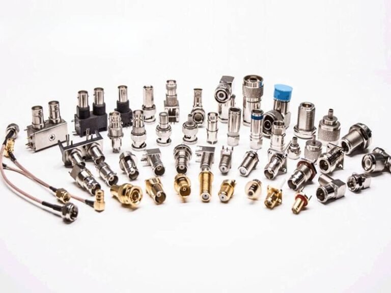
Coaxial cables are everywhere—from RF communication systems and industrial automation to medical equipment and high-frequency test setups. Yet despite their widespread use, coaxial cables are often treated as “plug-and-play” components, with testing reduced to a quick continuity check or a visual inspection. In reality, improper or incomplete testing is one of the most common root causes behind signal loss, EMI issues, intermittent failures, and costly system downtime.
Testing a coaxial cable is not just about confirming that electricity flows from one end to the other. A coaxial cable is a precision transmission line, and its performance depends on tightly controlled electrical, mechanical, and assembly parameters. Factors such as characteristic impedance, insertion loss, return loss, shielding effectiveness, and connector integrity all determine whether the cable will perform reliably in its real application environment.

To test a coaxial cable, you evaluate electrical performance (impedance, attenuation, return loss), continuity and shorts, shielding effectiveness, and mechanical reliability using tools such as multimeters, TDRs, network analyzers, and environmental tests. Proper coaxial cable testing ensures signal integrity, EMI control, safety, and compliance before installation or shipment.
For engineers, OEM manufacturers, and professional buyers, understanding how coaxial cables are tested—and why each test matters—can mean the difference between a stable system and months of troubleshooting. In the sections below, we break down coaxial cable testing step by step, from basic checks to advanced RF and compliance testing, using real-world practices applied in industrial and OEM production.
What Does It Mean to Test a Coaxial Cable?
Testing a coaxial cable means verifying that it meets required electrical, mechanical, and shielding performance before use. This includes checking impedance, signal loss, return loss, continuity, shielding integrity, and physical reliability. Proper testing ensures the cable can transmit signals accurately, resist interference, and operate safely in its intended application environment.
Testing a coaxial cable is often misunderstood as a single action, such as checking continuity or confirming signal presence. In professional and OEM environments, however, testing is a structured verification process that answers one fundamental question:
Can this coaxial cable perform reliably in its actual application, not just on the bench?
To answer that, testing must cover several distinct dimensions.
What performance aspects are tested?
A coaxial cable is a transmission system, not just a conductor. Testing therefore focuses on multiple performance aspects working together:
- Electrical performance – impedance stability, signal attenuation, return loss
- Signal integrity – reflection control, frequency response
- Shielding performance – resistance to EMI leakage and noise coupling
- Basic electrical integrity – continuity and isolation
- Mechanical reliability – resistance to bending, pulling, and handling stress
Each aspect targets a different failure mode. A cable may pass continuity tests but still fail in high-frequency operation due to impedance mismatch or poor shielding.
Why is electrical testing more than continuity?

Continuity testing only confirms that conductors are connected. It does not confirm that signals will travel correctly at operating frequencies.
Coaxial cables are designed to maintain a specific characteristic impedance (typically 50 Ω or 75 Ω). Deviations cause reflections, signal distortion, and power loss. Electrical testing evaluates whether the cable behaves as a controlled transmission line across its frequency range.
This is why professional testing always includes impedance, insertion loss, and return loss—not just resistance measurements.
How does testing relate to real application risk?
Every coaxial cable application carries risk:
- RF systems risk signal degradation
- Industrial systems risk EMI interference
- Power systems risk reflected energy damaging equipment
Testing translates abstract specifications into measurable risk reduction. For example, return loss testing directly predicts how much signal energy will reflect back into a transmitter. Shielding tests indicate susceptibility to external noise.
What problems does testing help prevent?
Comprehensive coaxial cable testing helps prevent:
- Intermittent signal loss
- Unexpected EMI issues
- Field failures after installation
- Costly troubleshooting and rework
- Compliance and inspection failures
Many “mysterious” system problems ultimately trace back to cables that were never properly tested beyond basic checks.
When should a coaxial cable be tested?
In professional workflows, testing occurs at multiple stages:
- After cable manufacturing – to verify material and construction quality
- After connector assembly – to confirm termination integrity
- Before shipment – as final quality assurance
- During troubleshooting – to isolate faults in existing systems
For OEM projects, testing before shipment is especially critical because post-installation access may be limited or impossible.
Which Electrical Tests Are Used for Coaxial Cables?
Electrical testing of coaxial cables focuses on verifying signal integrity and impedance control. Common tests include characteristic impedance measurement, insertion loss (attenuation), return loss, and VSWR testing. These electrical tests confirm that the cable transmits signals efficiently, minimizes reflections, and performs reliably across its intended frequency range.
Electrical testing is the core of coaxial cable validation. Unlike basic continuity checks, electrical tests evaluate how the cable behaves as a high-frequency transmission line, which is where most real-world failures originate.
Most common test
The most common electrical tests for coaxial cables are impedance verification, insertion loss measurement, and return loss testing. Together, these three tests form the minimum electrical performance baseline.
Impedance confirms that the cable matches the system requirement (usually 50 Ω or 75 Ω). Insertion loss shows how much signal power is lost as it travels through the cable. Return loss evaluates how much signal is reflected due to impedance mismatches. If any one of these tests fails, overall system performance is compromised—even if the cable appears electrically “connected.”
Impedance test
Characteristic impedance testing verifies that the coaxial cable maintains a stable impedance along its length.
This test is typically performed using a Time Domain Reflectometer (TDR) or a Vector Network Analyzer (VNA). These instruments detect impedance discontinuities caused by:
- Inconsistent dielectric materials
- Poor conductor centering
- Connector termination errors
Even small impedance variations can lead to signal reflections, timing errors, and degraded RF performance, especially at higher frequencies.
Insertion loss test
Insertion loss (also called attenuation) measures how much signal strength is lost as it passes through the coaxial cable.
The test compares the input and output signal levels across a defined frequency range. Loss increases with frequency, cable length, and material resistance. Excessive insertion loss may indicate:
- Low-quality conductors
- Improper dielectric selection
- Excessive cable length
Return loss test
Return loss testing measures how much signal energy is reflected back toward the source due to impedance mismatch.
This test is critical because reflected energy not only degrades signal quality but can also damage sensitive RF components. Poor return loss is often caused by:
- Improper connector installation
- Impedance mismatch between cable and connector
- Deformed dielectric near terminations
Return loss testing is therefore a key indicator of both cable quality and assembly workmanship.
VSWR test
Voltage Standing Wave Ratio (VSWR) is another way to express reflection performance.

A low VSWR value indicates efficient power transfer, while a high VSWR signals excessive reflections. VSWR testing is commonly used in RF and antenna systems because it provides an intuitive view of how well the cable is matched to the system.
In many specifications, return loss and VSWR limits are defined together, as they describe the same physical behavior from different perspectives.
Frequency response
Frequency response testing evaluates how electrical performance changes across the operating frequency range.
A coaxial cable may perform well at low frequencies but fail at higher ones due to dielectric losses, shielding limitations, or impedance instability. Frequency response testing ensures that:
- Performance remains consistent across required bands
- No unexpected resonances or roll-offs occur
This test is especially important for broadband, RF, and high-speed data applications.
Why electrical testing matters to buyers
From a buyer’s perspective, electrical testing translates specifications into measurable confidence.
Without electrical test data:
- Datasheets remain theoretical
- Assembly quality is unverified
- Field performance becomes unpredictable
At Sino-conn, electrical tests are performed according to customer specifications and application needs, ensuring that each coaxial cable assembly performs as intended—not just on paper, but in real systems.
How electrical tests guide the rest of the testing process
Electrical test results often determine whether additional testing is necessary. For example:
- Impedance instability may trigger connector re-evaluation
- Poor return loss may lead to shielding or termination review
This makes electrical testing the foundation upon which continuity checks, EMI testing, mechanical testing, and troubleshooting are built.
How Do You Test Coaxial Cable for Continuity and Shorts?
To test a coaxial cable for continuity and shorts, you verify that the center conductor and the shield each have a complete end-to-end electrical path, and that there is no unintended connection between them. This is commonly done using a multimeter or basic cable tester. These tests detect open circuits, short circuits, and assembly faults before advanced RF testing.
Continuity and short testing are often called “basic tests,” but in reality they catch a large percentage of real-world coaxial cable failures, especially those caused by connector assembly errors.
These tests do not evaluate signal quality—but they are essential prerequisites before any RF or EMI testing is meaningful.
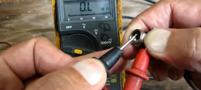
Multimeter test
Yes, a multimeter is the most common tool used to test coaxial cables for continuity and shorts.

Using a multimeter, you can:
- Confirm continuity of the center conductor
- Confirm continuity of the shield / outer conductor
- Detect short circuits between center and shield
You cannot, however, use a multimeter to test impedance, attenuation, return loss, or shielding effectiveness. For this reason, multimeter testing is best viewed as a screening test, not a performance test.
Continuity check
A continuity check verifies that each conductor forms a complete electrical path from one end of the cable to the other.
Typical steps include:
- Measure resistance from center pin to center pin
- Measure resistance from shield to shield
- Look for stable, low resistance readings
High resistance or unstable readings usually indicate:
- Poor crimping or soldering
- Broken strands inside the cable
- Incomplete connector termination
Continuity checks are especially important after connector installation, where most assembly-related defects occur.
Short detection
Short testing verifies that the center conductor is electrically isolated from the shield.
A proper coaxial cable should show:
- No continuity between center conductor and shield
Shorts are commonly caused by:
- Stray braid strands touching the center pin
- Deformed or melted dielectric
- Improper connector assembly
Even a partial short can cause severe signal loss or intermittent failures that only appear under vibration or temperature change.

Open circuit
An open circuit occurs when the conductor path is broken.
In coaxial cables, open circuits are often found at:
- Connector interfaces
- Strain-relief points
- Locations with excessive bending
Open circuits may pass visual inspection but fail continuity tests. This makes electrical checking essential even when the cable “looks fine.”
Assembly issues
Continuity and short tests are particularly effective at identifying assembly-related problems, including:
- Incorrect connector type
- Improper strip length
- Inadequate crimp force
- Misaligned center contacts
These issues are common in custom coaxial cable assemblies and are best caught early—before RF testing or shipment.
Limits of basic testing
While continuity and short testing are necessary, they are not sufficient for high-frequency or critical applications.
They cannot detect:
- Impedance mismatch
- Excessive insertion loss
- Poor return loss
- Inadequate shielding
Why continuity and short testing still matters
Despite their limitations, continuity and short tests:
- Prevent wasted time on failed RF tests
- Catch the most common assembly defects
- Reduce troubleshooting complexity
- Improve first-pass yield in production
At Sino-conn, every coaxial cable assembly undergoes 100% continuity and short testing as part of our three-stage inspection process, ensuring only electrically sound assemblies move on to advanced testing and shipment.
How this test fits into the full testing process
In practice, continuity and short testing acts as the gatekeeper:
- If it fails → assembly issue must be corrected
- If it passes → proceed to impedance, loss, and EMI testing
Understanding this role helps buyers and engineers interpret test results correctly and avoid misdiagnosing performance problems.
How Is Shielding and EMI Performance Tested?
Shielding and EMI testing evaluates how effectively a coaxial cable prevents electromagnetic interference from entering or escaping the cable. These tests measure shielding effectiveness, signal leakage, and noise susceptibility using RF instruments and controlled test setups. Proper EMI testing ensures signal integrity, regulatory compliance, and reliable operation in electrically noisy environments.
In coaxial cables, shielding is not a “nice-to-have” feature—it is often the difference between a stable system and an unpredictable one.
EMI problems are also among the hardest issues to troubleshoot after installation, which is why shielding and EMI performance must be verified during testing, not discovered in the field.
Shielding effectiveness
Shielding effectiveness measures how well a coaxial cable blocks external electromagnetic interference and prevents internal signals from leaking out.

This is typically expressed as attenuation in decibels (dB) across a frequency range. Higher values indicate better shielding performance. Testing may involve exposing the cable to controlled electromagnetic fields and measuring how much interference couples into the signal path.
Poor shielding effectiveness is often linked to:
- Low braid coverage
- Inconsistent foil layers
- Gaps or discontinuities near connectors
A cable that looks identical externally can perform very differently once shielding effectiveness is measured.
EMI leakage
EMI leakage testing focuses on identifying where interference escapes or enters the cable assembly.
Even if the bulk coaxial cable has good shielding, leakage frequently occurs at:
- Connector interfaces
- Shield termination points
- Areas under mechanical stress
Testing evaluates the entire cable assembly, not just the raw cable. This is critical for OEM and industrial applications, where EMI failures often originate at assembly transitions rather than within the cable itself.
Assembly impact
Shielding performance is heavily influenced by how the cable is assembled.
Factors that affect EMI results include:
- Connector type and design
- Shield termination method (360° grounding vs partial contact)
- Crimp quality and consistency
Two assemblies made from the same cable can show very different EMI performance if assembly quality differs. This is why EMI testing must be performed on finished assemblies, not just cable samples.
Frequency behavior
Shielding performance is frequency-dependent.
A coaxial cable may perform well at low frequencies but lose shielding effectiveness at higher frequencies due to:
- Skin effect
- Shield resonance
- Connector geometry limitations
EMI testing across the intended operating frequency range ensures that shielding remains effective where it actually matters, not just at a single test point.
Noise coupling
Noise coupling tests evaluate how susceptible a coaxial cable is to interference from nearby sources such as motors, power cables, or switching electronics.
In practical terms, this test answers the question:
Will this cable still work when installed next to noisy equipment?
Noise coupling issues are especially critical in industrial automation, medical devices, and RF systems, where electromagnetic environments are unpredictable.
Why shielding varies
Shielding and EMI performance varies widely between coaxial cables due to:
- Braid material (copper, tinned copper, aluminum)
- Braid density and weave
- Foil quality and overlap
- Consistency of manufacturing processes
Datasheets alone rarely capture these differences. Only testing reveals the true shielding capability of a cable assembly.
Typical Shielding Performance Indicators
| Indicator | What It Shows |
|---|---|
| Shielding effectiveness (dB) | EMI blocking capability |
| Leakage points | Weak spots in assembly |
| Frequency response | Performance consistency |
| Noise susceptibility | Real-world robustness |
What Mechanical and Environmental Tests Are Performed?
Mechanical and environmental testing evaluates whether a coaxial cable can withstand physical stress and harsh conditions without losing electrical performance. These tests include bending, tensile strength, vibration, temperature cycling, fire resistance, and resistance to oil, moisture, and UV exposure. Proper testing ensures long-term reliability in real installation and operating environments.
Bending test
Bending tests evaluate how well a coaxial cable tolerates repeated flexing during installation and use.
Typical procedures involve:
- Repeated bending cycles
- Testing at the minimum bend radius
- Monitoring for electrical degradation during and after bending
Failures in bending tests often indicate:
- Weak conductor stranding
- Inadequate dielectric resilience
- Poor strain relief design
Cables used in moving equipment, robotics, or test systems must pass bending tests to avoid intermittent signal loss.

Tensile strength
Tensile tests measure how much pulling force a cable and its connectors can withstand before damage occurs.
This test simulates:
- Installation pulling
- Accidental tension during maintenance
- Connector strain
If tensile strength is insufficient, failures usually appear at connector interfaces, leading to broken conductors or shield separation. Proper tensile testing ensures mechanical robustness without compromising electrical performance.
Vibration resistance
Vibration testing evaluates cable performance under continuous or cyclic mechanical vibration.
This is critical for applications such as:
- Industrial machinery
- Transportation systems
- Military and aerospace equipment
Vibration can loosen connectors, fatigue conductors, and degrade shielding contacts. A cable that passes static tests may still fail under vibration if assembly quality is poor.
Temperature cycling
Temperature cycling tests expose coaxial cables to repeated high and low temperature extremes.
These tests assess:
- Thermal expansion mismatch between materials
- Insulation cracking or deformation
- Connector loosening due to expansion and contraction
Temperature cycling is essential for outdoor, automotive, and industrial applications where cables experience frequent thermal changes.
Fire resistance
Fire resistance testing verifies how a cable behaves when exposed to flame or high heat.
Depending on application, tests may evaluate:
- Flame propagation
- Self-extinguishing behavior
- Smoke generation
Fire performance is especially important for building installations, transportation, and regulated environments where safety compliance is mandatory.
Oil and chemical resistance
Oil and chemical resistance tests evaluate how cable jackets and insulation respond to prolonged exposure to industrial substances.
Poor resistance can cause:
- Jacket swelling or cracking
- Loss of flexibility
- Degraded dielectric properties
This testing is critical in factories, automotive environments, and heavy equipment installations.
Moisture and corrosion
Moisture resistance testing examines how cables perform in humid or wet conditions.
Tests may include:
- High-humidity exposure
- Water immersion
- Corrosion evaluation of conductors and shields
Moisture ingress is a common cause of long-term signal degradation and intermittent faults, especially in outdoor or marine environments.
UV exposure
UV testing evaluates resistance to sunlight-induced aging.
Cables used outdoors may suffer from:
- Jacket embrittlement
- Cracking
- Loss of flexibility
UV resistance ensures long service life in outdoor installations without premature material failure.
Mechanical & Environmental Risks vs Test Coverage
| Risk Factor | Test Purpose |
|---|---|
| Repeated movement | Bending & fatigue tests |
| Installation stress | Tensile tests |
| Machinery vibration | Vibration tests |
| Temperature extremes | Thermal cycling |
| Fire exposure | Flame resistance |
| Industrial fluids | Oil & chemical tests |
| Outdoor exposure | UV & moisture tests |
What Standards Apply to Coaxial Cable Testing?
Coaxial cable testing is governed by international safety, performance, and material compliance standards such as UL, IEC, RoHS, REACH, and PFAS regulations. These standards define test methods, acceptance criteria, and documentation requirements to ensure electrical reliability, fire safety, and environmental compliance across global markets.
UL standards
UL (Underwriters Laboratories) standards are widely required for products sold or installed in North America.
For coaxial cables, UL standards typically cover:
- Electrical safety
- Flame resistance and fire propagation
- Temperature ratings
- Construction consistency
UL-compliant testing ensures that a cable can be legally used in regulated environments such as buildings, industrial systems, and commercial equipment. For buyers, UL recognition simplifies inspections and reduces approval delays.
IEC standards
IEC (International Electrotechnical Commission) standards provide globally recognized testing frameworks.
IEC standards define:
- Electrical performance requirements
- Mechanical durability tests
- Environmental resistance criteria
IEC-based testing is especially important for international OEM projects, where cables must meet consistent performance expectations across different regions. Many customers use IEC standards as a neutral reference when sourcing from global suppliers.
Electrical performance criteria
Standards specify how electrical tests must be conducted, not just which parameters are measured.
This includes:
- Test setup requirements
- Frequency ranges
- Calibration rules
- Acceptance limits
By following standardized electrical testing, results become comparable and repeatable. This prevents disputes caused by inconsistent test methods or selective reporting.
Fire and safety compliance
Fire-related standards address how cables behave under flame or high-temperature exposure.
Depending on application, this may include:
- Flame spread limits
- Self-extinguishing behavior
- Smoke generation
Fire compliance is critical for building installations, transportation systems, and public infrastructure. Failure to meet fire standards can result in rejected installations or mandatory rework.
Material regulations
Material regulations such as RoHS, REACH, and PFAS restrictions govern the chemical composition of cable materials.
Compliance ensures that:
- Hazardous substances are restricted
- Products meet environmental and health regulations
- Imports are not delayed or rejected
Although these regulations are not performance tests, compliance must be supported by documentation and, in some cases, material verification testing.
Documentation requirements
Standards are closely tied to documentation.
Buyers commonly request:
- Test reports
- Certificates of Conformity (COC)
- Country of Origin (COO)
- Material declarations
Clear documentation allows procurement teams to verify compliance quickly and supports audits, certifications, and customs clearance.
Application differences
Not all applications require the same standards.
For example:
- Medical and military applications often require stricter testing
- Commercial systems follow general safety and performance standards
- Consumer products may prioritize cost and basic compliance
Understanding which standards apply to your specific application prevents both under-compliance and unnecessary over-testing.
Conclusion
Coaxial cable testing is not just about passing numbers on a report—it’s about ensuring that your system works reliably in the real world.

Whether you are validating a new design, replacing an existing cable, or scaling up OEM production, Sino-conn provides engineering-driven testing, fast response, and flexible customization—from 1 piece to mass production.
Send us your drawing, specification, or reference sample.
We’ll help you test, validate, and deliver coaxial cable assemblies you can trust.