Skip to content
People often use the words “RF port” and “coaxial port” like they’re interchangeable. That’s why a lot of inquiries start like this: “We need an RF port cable,” and then the customer sends a photo of a coax connector—without frequency, impedance, or any datasheet. The connector might look familiar, but the real question is: what signal is going through it, and what performance is expected? If that part is unclear, the project can go wrong even if the cable “fits.”
Here’s what we see in real sourcing:
- Engineers talk about impedance, loss, and EMI stability.
- OEM factories care about assembly yield, lead time, and consistent parts.
- Traders often only know the model or a picture and want “same as original.”
An RF port is defined by what it carries: radio-frequency signals that are sensitive to impedance, shielding, and termination quality. A coaxial port is defined by how it is built: a center conductor with a surrounding shield in a coaxial structure. Many RF ports are coaxial, but not all coaxial ports are used for RF. The difference affects connector choice, performance risk, and cost.
A lot of expensive delays happen when someone assumes “coaxial” automatically means “RF-ready.” The good news is: once you know what to check, it becomes straightforward—and fast to confirm before production.
What Are RF and Coaxial Ports?
RF and coaxial ports are not the same concept. RF ports are interfaces used for high-frequency signals, where impedance and EMI control matter a lot. Coaxial ports are interfaces built with a coaxial structure (center conductor + shield). Many RF ports use coaxial construction, but coaxial ports may also carry lower-frequency signals like video or control, where RF performance is not required.
What is an RF port?
An RF port is a port used for radio-frequency signal paths. It’s defined by the signal behavior, not by the connector’s appearance. When the signal is RF, small changes in geometry and termination can change performance. That’s why engineers treat RF ports as “performance interfaces,” not just mechanical connectors.
What customers usually need to define for an RF port (even if they only have a photo):
- frequency range (example: Wi-Fi, GPS, cellular, test equipment)
- impedance requirement (often 50Ω)
- allowed loss over the real cable length
- EMI environment (near motors, power supplies, medical devices, etc.)

RF ports are common in:
- antennas and antenna feeders
- GPS/GNSS modules
- Wi-Fi, cellular, and wireless devices
- RF measurement and test systems
A practical rule: if the signal is RF and performance matters, the port must be treated as a system: connector + cable + termination method.
What is a coaxial port?
A coaxial port is defined by coaxial structure: a center conductor surrounded by dielectric and an outer shield. This structure helps maintain stable impedance and improves noise resistance compared to unshielded wiring. Coaxial is a construction method, not a promise of RF performance.
Coaxial ports are used for:
- video (often 75Ω)
- instrumentation and signal transmission
- some RF applications (often 50Ω)
- devices where shielding is needed but frequency is not extremely high

Why confusion happens:
Many coaxial connectors look similar across applications. But the same-looking coaxial port can be used in different ways:
- A 75Ω coaxial port for video may not meet the needs of RF work at higher frequencies.
- A coaxial port might have acceptable shielding for short runs, but not for high-noise environments.
So when a customer asks for a “coaxial port cable,” the next question should be: “Is it being used as an RF path or not?”
Are RF and coaxial ports the same thing?
No, and mixing them up is one of the fastest ways to create hidden risk.
A simple way to keep it clear:
- RF describes the signal category and performance demand
- Coaxial describes the physical structure used to carry signals
Most RF ports are coaxial because coaxial structure is a good way to control impedance and EMI. But these are the common mismatch scenarios:
Mismatch scenario 1: “It fits, but performance drops.”
A customer replaces an RF port with a coaxial port that has different impedance or frequency limit. The connector mates, but the system becomes unstable.
Mismatch scenario 2: “It works in sample, fails in mass production.”
Specs were never clarified, and termination variation changes RF performance.
Mismatch scenario 3: “Only a photo was provided.”
A trader sends a photo and asks for the same. Without impedance and frequency, the factory must confirm by structure and application.
At Sino-Conn, we reduce these risks by confirming the missing details first, then issuing drawings (CAD to PDF) for approval before production.
RF and coaxial ports
| What you want to confirm | RF and coaxial ports impact | Why it matters |
|---|---|---|
| Signal type | RF and coaxial ports differ by use | Determines performance needs |
| Frequency range | RF and coaxial ports must match | Higher frequency = higher risk |
| Impedance | RF and coaxial ports often require 50Ω/75Ω | Mismatch causes reflection |
| Cable length | RF and coaxial ports loss adds up | Longer = more attenuation |
| EMI environment | RF and coaxial ports need shielding plan | Noise causes instability |
| Connector series | RF and coaxial ports compatibility | Fit + electrical stability |
Quick checklist: If you only have a photo, what should you send?
If you don’t know the specs, you can still move fast if you provide:
- the device/application (Wi-Fi? GPS? video? test?)
- cable length you need
- connector names if known (or clear photos of both ends)
- any “must-have” requirements (UL, RoHS, REACH, halogen-free, PFAS needs)
This is usually enough for Sino-Conn to confirm whether it’s an RF use case or a non-RF coaxial use case, then recommend the right structure and connector approach.
How Do RF and Coaxial Ports Work?
RF and coaxial ports work by transmitting signals through a controlled impedance path, but the key difference lies in performance sensitivity. RF ports operate at high frequencies where impedance accuracy, shielding continuity, and termination quality are critical. Coaxial ports rely on the same physical structure but may be used at lower frequencies where performance tolerance is wider.
How do RF and coaxial ports transmit signals?
Both RF and coaxial ports transmit signals using a center conductor and surrounding shield, but how sensitive that transmission is depends on frequency and application.
In a coaxial structure:
- the center conductor carries the signal
- the dielectric controls impedance
- the outer shield provides a return path and EMI protection

For coaxial ports used at low or medium frequency, small variations in structure usually don’t cause visible issues. The signal has enough margin.
For RF ports, the situation is different:
- signal wavelengths are shorter
- impedance mismatch causes reflection
- even small geometry changes affect performance
This is why RF ports are usually specified with:
- tighter impedance tolerance
- stricter connector mating requirements
- clearer limits on cable length and bending
A coaxial port may “work” electrically, but an RF port must work predictably, not just pass continuity tests.
How do impedance and shielding affect RF and coaxial ports?
Impedance and shielding are where RF and coaxial ports truly separate.
Impedance
- RF ports are almost always 50Ω
- coaxial ports may be 50Ω or 75Ω, depending on use
Impedance mismatch causes:
- signal reflection
- reduced power transfer
- unstable performance
Shielding
- RF ports demand continuous shielding from connector to cable
- coaxial ports for lower frequencies may tolerate partial shielding loss
Common real-world issue:
The cable meets impedance specs, but EMI problems appear because the shield is not fully bonded at the connector.
At Sino-Conn, RF port assemblies are treated as a complete signal path, not just a cable with connectors attached.
How does frequency range differ in RF and coaxial ports?
Frequency range is often assumed, not confirmed—and that causes problems.
Typical ranges:
- Coaxial ports (general use): DC to hundreds of MHz
- RF ports: MHz to several GHz
Why this matters:
- attenuation increases with frequency
- shielding effectiveness becomes critical
- connector performance limits appear
A coaxial connector designed for video may look similar to an RF connector, but:
- its impedance control may degrade above 1 GHz
- insertion loss increases faster
- reflections become measurable
This is why engineers often specify RF ports by connector series + frequency rating, while coaxial ports may be specified only by structure.
How RF and coaxial ports work in practice
| Factor | RF Ports | Coaxial Ports |
|---|---|---|
| Frequency sensitivity | Very high | Medium to low |
| Impedance tolerance | Tight | Wider |
| Shielding continuity | Critical | Important |
| Reflection risk | High | Lower |
| Termination quality | Key factor | Moderate factor |
Which Connectors Are Used for RF and Coaxial Ports?
RF and coaxial ports often use similar connector families, but the difference lies in electrical tolerance, frequency rating, and termination precision. RF ports require connectors designed for stable impedance and high-frequency performance, while coaxial ports may use connectors optimized for mechanical fit and shielding at lower frequencies. Choosing the wrong connector usually causes signal loss or EMI issues, even if it mates correctly.
Which connector families are commonly used for RF and coaxial ports?
Many customers assume connector names alone define performance. In reality, the same connector family can include very different performance levels.
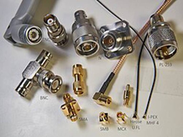
Common connector families seen in RF and coaxial ports:
- SMA Used widely in RF applications. Typically 50Ω. Suitable for GHz-level signals.
- SMB / SMC Compact connectors used in RF modules and internal assemblies.
- MCX / MMCX Small-size connectors for antennas, GPS, wireless modules.
- BNC Often used in video and instrumentation; can be 50Ω or 75Ω.
- TNC Threaded version of BNC, better vibration resistance.
- N-type Larger RF connector used for outdoor and high-power RF applications.

What customers often overlook
The connector family name is not enough. Within the same family:
- frequency rating can vary widely
- impedance control quality can differ
- mechanical tolerance can affect EMI
That’s why Sino-Conn always asks for either:
- a full connector part number, or
- clear photos plus application details
How do RF connectors differ from general coaxial connectors?
The difference is not cosmetic—it’s functional.
RF connectors are designed to:
- maintain stable 50Ω impedance through the connector body
- minimize reflection at high frequency
- keep shielding continuous through 360° contact
General coaxial connectors focus more on:
- mechanical robustness
- ease of installation
- cost efficiency
Key technical differences customers care about:
| Aspect | RF Connectors | Coaxial Connectors |
|---|---|---|
| Frequency range | High (GHz-level) | Low–medium |
| Impedance control | Tight | Wider |
| Reflection tolerance | Very low | Higher |
| EMI sensitivity | Very high | Medium |
| Cost | Higher | Lower |
Real-world issue we see often
A connector fits perfectly and passes continuity tests, but RF performance degrades. The root cause is almost always connector impedance mismatch, not cable failure.
How does connector impedance (50Ω vs 75Ω) affect RF and coaxial ports?
Impedance is not just a cable spec—it’s a connector spec too.
Most RF connectors are:
- 50Ω, matched to RF systems
Most video coaxial connectors are:
- 75Ω, optimized for signal bandwidth in video systems
What happens if impedance is mixed:
- 50Ω cable + 75Ω connector → reflection
- 75Ω cable + 50Ω connector → signal distortion
Even short mismatches can cause:
- unstable RF performance
- reduced antenna efficiency
- measurement errors in test systems
Common sourcing mistake
Customers replace a connector visually matching the original but ignore impedance marking. The system “works,” but performance margin drops.
At Sino-Conn, impedance is always confirmed at both connector and cable level before quoting.
How does frequency rating limit connector selection for RF and coaxial ports?
Every connector has a practical frequency ceiling, even if it is not clearly stated in customer documentation.
Typical examples:
- low-grade coaxial connectors: suitable below 1 GHz
- standard RF SMA connectors: several GHz
- precision RF connectors: higher GHz ranges
Why frequency rating matters:
- insertion loss increases sharply near the limit
- impedance stability degrades
- EMI leakage becomes visible
Important customer insight
If your system runs near the upper frequency limit of a connector, production variation alone can push performance out of range.
Sino-Conn often recommends one level higher frequency rating than the minimum requirement to ensure stable mass production.
How does termination quality affect connector performance?
Connector performance is not only about the connector itself—it’s about how it is terminated.
Key termination factors:
- cable OD must match connector design
- crimp height and compression force must be controlled
- braid must make full contact with connector shell
- dielectric deformation must be avoided
Common production problem
A sample passes testing, but mass production shows inconsistency. In most cases, termination variation—not connector choice—is the cause.
Sino-Conn controls this through:
- defined work instructions
- process inspection during assembly
- final inspection before shipment
How do original and alternative connectors compare for RF and coaxial ports?
This is one of the most common customer questions.
Original (brand-name) connectors
- higher cost
- longer lead time
- stable performance history
- limited customization flexibility
Alternative connectors
- lower cost
- faster availability
- flexible supply
- performance often sufficient for many applications
How customers decide
- RF-critical systems → original connectors preferred
- cost-sensitive or time-critical projects → alternatives acceptable
Sino-Conn explains this trade-off transparently so customers can decide based on risk tolerance, not assumptions.
Connector selection checklist for RF and coaxial ports
| Question | Why It Matters |
|---|---|
| What frequency does the signal run at? | Determines connector rating |
| Is impedance 50Ω or 75Ω? | Prevents reflection |
| How sensitive is the system to loss? | Sets performance margin |
| Is vibration present? | Influences connector style |
| Is cost or stability more important? | Guides original vs alternative |
Where Are RF and Coaxial Ports Used?
RF and coaxial ports are used across different industries based on signal frequency, sensitivity, and reliability requirements. RF ports are used where high-frequency signals and signal integrity are critical. Coaxial ports are used where shielding and stable transmission are needed, but frequency and impedance tolerance are less strict. The application environment determines which port type is appropriate.
Which applications rely on RF ports?
RF ports are used in applications where signal quality directly affects system function. In these systems, even small signal loss or reflection can cause visible performance problems.
Common RF port applications include:
- Wireless communication systems Wi-Fi, cellular, Bluetooth, and RF modules all rely on RF ports to connect antennas or internal RF paths.
- Antenna connections External and internal antenna ports are almost always RF ports, because impedance mismatch directly reduces transmission range.
- GPS / GNSS positioning systems GPS signals are weak by nature. Poor RF port performance leads to slow positioning or signal drop.
- RF test and measurement equipment Spectrum analyzers, signal generators, and test fixtures require highly stable RF ports to avoid measurement error.
- Medical and scientific equipment Imaging, monitoring, and sensing devices often use RF paths that must remain stable in noisy environments.

What these applications have in common
- operating frequency often in MHz–GHz range
- low tolerance for reflection and loss
- strict EMI control
If a port failure would affect accuracy, range, or stability, it is almost always treated as an RF port.
Which applications use coaxial ports?
Coaxial ports are used where shielded signal transmission is needed, but where the system can tolerate wider electrical margins.
Common coaxial port applications include:
- Video and imaging systems CCTV, broadcast video, and industrial cameras often use 75Ω coaxial ports.
- Instrumentation and monitoring Oscilloscopes, lab instruments, and signal monitoring devices frequently use coaxial ports for stable connections.
- Industrial control and automation Sensors and control signals routed through noisy environments benefit from coaxial shielding.
- General electronic equipment Devices requiring durable, shielded connections without extreme RF precision.

In these applications:
- frequency is usually lower or fixed
- impedance tolerance is wider
- mechanical durability and cost are important
This is why coaxial ports are common in OEM manufacturing, where availability and consistency matter as much as performance.
How do industries differ in RF and coaxial port usage?
Different industries prioritize ports differently based on risk and regulation.
| Industry | RF Ports | Coaxial Ports | Key Reason |
|---|---|---|---|
| Wireless & telecom | ✔✔✔ | ✖ | High frequency, signal critical |
| Automotive | ✔✔ | ✔ | Mixed RF + control signals |
| Medical | ✔✔✔ | ✔ | Accuracy and EMI sensitivity |
| Industrial automation | ✖ | ✔✔✔ | Shielding, durability |
| Video & broadcast | ✖ | ✔✔✔ | 75Ω coax standard |
| Consumer electronics | ✔ | ✔✔ | Cost vs performance balance |
Important insight for customers
The same connector type may be used across industries, but the performance expectation is completely different. Copying a port from one industry to another without re-checking is a common source of failure.
How do engineers decide whether a port should be RF or coaxial?
Engineers usually do not start with connector names. They start with signal behavior and risk.
Typical decision path:
- What frequency does the signal operate at?
- How sensitive is the system to signal loss or reflection?
- Is the signal amplified or weak at the source?
- What EMI sources exist nearby?
- Is performance or cost the top priority?
If the answers point to high sensitivity, the port is treated as RF.
If not, a coaxial solution is often sufficient and more cost-effective.
At Sino-Conn, when customers are unsure, we help translate:
- application description
- environment
- cable length
into a clear RF or coaxial port recommendation.
Where do customers most often choose the wrong port type?
From real project experience, mistakes usually happen in these situations:
- “The original design used RF, but we replaced it with coax to save cost.” Result: reduced range, unstable performance.
- “The connector looks the same, so it should work.” Result: impedance mismatch and EMI issues.
- “It passed the sample test.” Result: mass production inconsistency due to tighter RF tolerance not being controlled.
These problems often appear after installation, when it is too late to change the port easily.
Quick application check — RF or coaxial port?
| Question | If “Yes” → Likely RF | If “No” → Likely Coax |
|---|---|---|
| Frequency above hundreds of MHz? | ✔ | ✖ |
| Signal affects system accuracy? | ✔ | ✖ |
| Weak signal source (antenna/GPS)? | ✔ | ✖ |
| Strong EMI environment? | ✔ | ✔ |
| Cost more important than margin? | ✖ | ✔ |
How Do RF and Coaxial Ports Affect Cable Assemblies?
RF and coaxial ports directly influence cable assembly design, including cable structure, connector selection, shielding method, and quality control. RF ports require tighter electrical and mechanical control, while coaxial ports allow more flexibility. Treating both the same often leads to over-costing or hidden performance risks.
How do RF and coaxial ports change cable specifications?
Once a port is identified as RF or general coaxial, cable specifications must follow.
RF port assemblies typically require:
- tighter impedance tolerance
- lower attenuation cable constructions
- controlled dielectric materials
- strict bend radius limits
Coaxial port assemblies may allow:
- wider impedance tolerance
- thicker or more cost-effective jackets
- greater flexibility in routing
Common mistake:
Using the same cable structure for both RF and coaxial ports “to simplify sourcing.” This often results in:
- unnecessary cost for coaxial applications
- unstable performance for RF applications
At Sino-Conn, cable structure is always matched to port function, not just connector appearance.
How do EMI requirements differ for RF and coaxial ports?
EMI is a concern for both, but the tolerance is very different.
RF ports:
- require continuous shielding from connector to cable
- are sensitive to small shielding gaps
- depend heavily on termination quality
Coaxial ports:
- still require shielding
- may tolerate partial performance loss without visible system impact
Real-world issue:
A cable passes continuity and visual inspection, but EMI issues appear only after installation. In most cases, the port was treated as coaxial when it should have been treated as RF.
This is why Sino-Conn performs:
- process inspection during termination
- final inspection before shipment
- consistency checks across batches
How does customization differ for RF and coaxial ports?
Customization is common in both cases, but the risk profile is different.
RF port customization focuses on:
- maintaining electrical consistency
- controlling tolerance stack-up
- verifying performance impact
Coaxial port customization focuses on:
- length adjustment
- connector orientation
- material selection
- cost optimization
Both require drawings and confirmation before production, but RF projects often need more engineering involvement, while coaxial projects move faster.
Cable assembly impact by port type
| Factor | RF Ports | Coaxial Ports |
|---|---|---|
| Cable loss control | Strict | Moderate |
| EMI sensitivity | Very high | Medium |
| Custom flexibility | Limited | High |
| Cost optimization | Secondary | Primary |
| QC intensity | Very high | High |
How Can Sino-Conn Support RF and Coaxial Ports?
Sino-Conn supports both RF and coaxial port projects by helping customers confirm specifications, providing fast drawings and samples, and offering flexible connector and cable options. With no MOQ, short lead times, and full inspection, Sino-Conn helps customers move from unclear input to reliable production quickly.
How does Sino-Conn confirm RF and coaxial port specs?
Customers often start with:
- a model number
- a drawing
- or just photos
Sino-Conn confirms specifications by:
- reviewing connector type and interface
- checking cable structure and OD
- clarifying application and signal type
- rebuilding missing parameters
Drawings are provided:
- usually within 3 days
- sometimes within 30 minutes for urgent cases

Production only starts after customer approval.
How fast can Sino-Conn sample RF and coaxial ports?
Typical timelines:
- samples: 2 weeks standard, as fast as 2–3 days urgent
- mass production: 3–4 weeks standard, about 2 weeks urgent
There is no MOQ—even 1 piece is acceptable for testing and evaluation.
How do MOQ, pricing, and connector options compare?
Sino-Conn offers:
- original connectors for customers who need brand control
- alternative connectors for faster delivery and lower cost
Pricing depends on:
- market (US, EU, Asia)
- industry (medical, military, commercial)
- order volume and customization level
This flexibility allows customers to balance performance, cost, and lead time, instead of being locked into one option.
Discuss Your RF or Coaxial Port Project with Sino-Conn
If you are not sure whether your interface is an RF port or a general coaxial port, you are not alone. Most delays happen before manufacturing starts—when specifications are unclear.
You can start with:
- a drawing
- a part number
- or even just photos and an application description
Sino-Conn will help you confirm the right port type, cable structure, and connector solution—then move quickly to drawings, samples, and production.
Contact Sino-Conn today to discuss your RF and coaxial port cable assemblies and get a solution that matches your real application, not assumptions.