Skip to content
 How to Join Coaxial Cable With Connectors: A Complete Guide
- andy
Joining a coaxial cable with the correct connector seems simple—strip the cable, attach the pin, crimp the shell, and you’re done. But anyone who works with RF systems, telecom infrastructure, aerospace modules, medical electronics, or IoT hardware knows the truth: coaxial termination is a precision task. A cable that looks perfect on the outside can fail spectacularly under RF testing if the dielectric is crushed, the braid is uneven, or the pin depth is off by even 0.3 mm. These micro-errors cause high VSWR, unstable impedance, poor shielding, intermittent signals, and long-term reliability failures.
In other words—joining a coaxial cable is not about “making a physical connection.” It is about maintaining electrical integrity across a controlled transmission line.
To join a coaxial cable with connectors, you must strip the cable to precise lengths, prepare the braid and dielectric, crimp or solder the center pin, insert the cable into the connector body, and finish with a ferrule or crimp sleeve. The connection must maintain correct impedance, shielding continuity, and mechanical strength. Using the right tools, cable specs, and connector type ensures low loss, low VSWR, and long-term stability.
That’s why engineers take coax termination seriously—and why many OEMs and designers ultimately outsource coax assemblies to manufacturers such as Sino-Conn, where cable tolerances, connector fit, and RF performance are guaranteed through strict process control.
But before we get into expert-level considerations, let’s start with the fundamentals: what these cables are, how connectors differ, and how to perform a proper termination yourself. Stay with me—because understanding coaxial structure will make every step of the process much clearer.
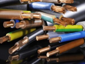
What Is a Coaxial Cable and How Does It Work?
A coaxial cable works by guiding high-frequency signals through a centered conductor surrounded by a dielectric, shield, and outer jacket. Its precise geometry controls impedance, typically 50 or 75 ohms. Any deformation in the dielectric, braid, or pin depth disrupts signal flow and increases loss. Proper connector termination preserves the cable’s electrical symmetry and shielding continuity.
Coaxial cables are engineered transmission lines. Their performance depends heavily on maintaining accurate structural alignment—unlike power cables, which tolerate more irregularity.
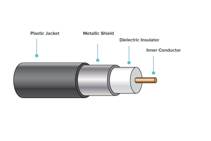
Main Layers of a Coaxial Cable
A basic coax cable consists of:
| Layer | Description | Importance |
|---|---|---|
| Center Conductor | Stranded or solid copper | Carries RF signal |
| Dielectric | PTFE, PE, foam | Sets impedance |
| Shield | Braid + foil | Controls EMI & return loss |
| Outer Jacket | PVC, LSZH, TPE, FEP | Environmental protection |
Deforming or trimming any of these layers inaccurately disrupts the coax’s impedance profile.
Performance Factors That Matter
- Impedance (50Ω or 75Ω) – mismatch causes reflections.
- Shielding coverage (80–95%) – affects EMI immunity.
- Outer diameter tolerance – determines connector compatibility.
- Dielectric hardness & type – affects high-frequency performance.
- Flexibility & bending radius – critical for moving applications.
Sino-Conn often receives customer photos of cables with no technical specs. Even then, we rely on experience and industry standards to identify OD, material type, shielding density, and connector matches.
Why Termination Affects Performance
A poor termination may:
- skew impedance
- increase VSWR
- weaken shielding
- introduce micro-arcs
- cause mechanical failure under vibration
This is why engineers insist on precise termination procedures—and why we include 100% inspection on all assemblies.
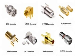
Which Coaxial Connectors Are Common and How Do They Differ?
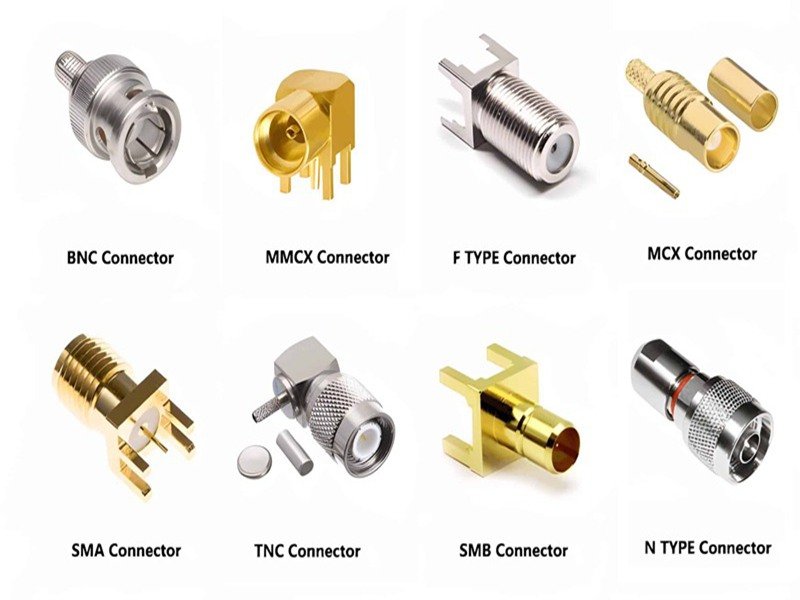
Coaxial connectors differ by frequency range, mechanical locking method, impedance, and size. SMA, SMB, BNC, TNC, N-type, and F-type each serve different RF, telecom, and broadcast applications. Matching connector type to cable OD and dielectric size is critical to avoid loss and ensure compatibility.
Common Connector Types and Applications
| Connector Type | Impedance | Application |
|---|---|---|
| SMA | 50Ω | RF modules, antennas, test gear |
| SMB/SMC | 50Ω | Compact wireless devices |
| BNC | 50/75Ω | Test equipment, broadcast |
| TNC | 50Ω | Outdoor RF, rugged use |
| N-Type | 50Ω | High-power RF, telecom |
| F-Type | 75Ω | Consumer TV systems |
Matching Connectors to Cable Types
Incorrect OD sizing results in:
- loose fit
- crushed dielectric
- inconsistent pin retention
Sino-Conn engineers routinely evaluate OD to 0.01 mm precision before choosing ferrules, pins, and connector bodies.
Original Brand vs. Equivalent Alternatives
Customers often ask whether to use “original” or “compatible” connectors.
For urgent orders, Sino-Conn uses equivalent connectors with stable performance and rapid availability.
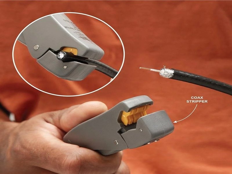
What Tools Do You Need to Join Coaxial Cable?
To join coaxial cable, you need precision strippers, a crimp tool or soldering tools, heat-shrink material, and testing equipment. Each tool ensures clean, uniform stripping, accurate pin placement, and reliable shield contact—essential for low-loss RF performance.
Essential Tools
- Coax stripping tool (preset lengths ensure accuracy)
- Crimp tool with matched die sets
- Soldering iron for center pins when required
- Heat gun + shrink tubing
- Continuity tester / TDR / VSWR meter
Why Tool Quality Matters
Cheap strippers often tear the braid or cut into the dielectric.
A poorly sized crimp die can deform the ferrule or connector body.
At Sino-Conn, production uses calibrated tools with ±0.02 mm clamping tolerances.
How to Join Coaxial Cable With Connectors (Step-by-Step)
Joining coax requires stripping the layers to exact lengths, preparing the braid, attaching the center pin, inserting the connector body, and crimping the ferrule. Accurate dimensions and careful handling protect impedance stability and signal performance.
How to Attach a Connector to a Coax Cable
This answers your requested sub-topic:
- Strip cable to required lengths
- Fan braid evenly
- Trim dielectric cleanly
- Crimp or solder center pin
- Insert into connector body
- Crimp ferrule
- Test electrical continuity
Step 1: Cutting & Stripping
Any deviation affects impedance.
Foam dielectrics require extra care.
Step 2: Preparing the Dielectric
Avoid nicks or indentations—they increase return loss.
Step 3: Crimping or Soldering the Pin
Crimping is faster; soldering offers more precision for micro-coax.
Step 4: Securing the Connector Body
Ensure the pin seats fully; partial insertion weakens VSWR.
Step 5: Electrical Testing
A proper assembly shows strong continuity, no shorts, and stable impedance.
How Do You Join Two Coaxial Cables Together?
You can join two coaxial cables using an inline coax coupler (barrel connector), by re-terminating each cable with matching connectors, or through a high-quality splice. Couplers maintain impedance and shielding better than DIY twisting or soldering.
Methods
- Inline coupler (best)
- Re-terminate both ends
- Use factory-built extensions
What Not to Do
Never twist two coax cores together
Never tape bare shields
Both cause massive loss and EMI leakage.
How Do You Choose the Right Connector and Cable Specs?
Choosing the right coax assembly requires evaluating OD, dielectric type, shielding, impedance, materials, environmental ratings, and connector compatibility. These parameters ensure performance and long-term durability.
Critical Specification Parameters
When Datasheets Are Necessary
Sino-Conn provides detailed specifications: impedance, OD, shielding %, materials, ROHS/REACH/PFAS compliance, flame ratings, and more.
Customization Options
- Length
- Pin-out
- Materials
- Overmolding
- Flexibility class
- High-temp ratings
How to Ensure Professional Quality in Coaxial Cable Assemblies
High-quality coax assemblies require professional tooling, controlled manufacturing, precision drawings, and 100% electrical inspection. These steps ensure stable impedance, low loss, and long-term reliability.
Prototyping & Lead Time
Sino-Conn delivers:
- Samples: 2 weeks (urgent: 2–3 days)
- Mass production: 3–4 weeks (urgent: 2 weeks)
Engineering Drawings
We provide drawings within 30 minutes to 3 days, depending on complexity.
All orders receive drawing approval before production.
Inspection Workflow
Every assembly is checked three times:
- Process inspection
- Post-assembly inspection
- Pre-shipment evaluation
Industries with Higher Requirements
- Medical
- Military
- Aerospace
- Telecom
These industries require tighter tolerance, specific materials, and stricter documentation.
When Should You Use a Custom Coaxial Cable Assembly Instead of DIY?
Custom coax assemblies are recommended when precision impedance, low loss, micro-coax connectors, harsh environments, or certification requirements exceed what DIY methods can safely achieve.
When DIY Is Not Enough
- High-frequency RF
- Connectors smaller than SMA
- Ultra-flexible or ultra-thin micro-coax
- Outdoor or high-temperature use
- Telecommunications infrastructure
- Medical electronics
What Sino-Conn Offers
- No MOQ (1 pc is fine)
- Fast engineering support
- Precise assembly
- Connector substitution options (original or cost-optimized)
- Full certification packages

Conclusion:
Joining a coaxial cable with connectors is a craft—a mix of mechanical accuracy, electrical understanding, and manufacturing discipline. While DIY solutions work for small projects, professional RF systems require controlled tolerances, stable materials, and validated inspection.
If you need custom coaxial cables, RF assemblies, drawings, engineering advice, samples, or high-volume production, Sino-Conn can help.
We support distributors, engineers, R&D teams, and OEM factories worldwide with fast lead times, no MOQ, competitive pricing, and 100% quality inspection.
Tell us your cable type, connector model, or simply send a photo—we’ll handle the rest.
Related Keywords :coaxial cable assembly, coax connector installation, RF cable termination, SMA BNC connectors, join coax cables, custom cable assemblies, impedance matching, RF engineering, Sino-Conn, coax crimping guide

With over 18 years of OEM/ODM cable assemblies industry experience, I would be happy to share with you the valuable knowledge related to cable assemblies products from the perspective of a leading supplier in China.
manufacturer catalogue
Get A Sample Now From Factory→
Get a quote quickly
Here, developing your OEM/ODM custom cable assemblies collection is no longer a challenge—it’s an excellent opportunity to bring your creative vision to life.