Skip to content
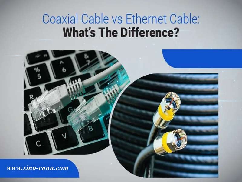
When people search for coaxial cable vs ethernet, they are usually trying to solve a practical problem: a device needs connectivity, a network needs stability, or a product design requires the right transmission medium. Both cables move electrical signals, yet they behave very differently in real-world systems. Choosing the wrong one can lead to signal loss, unstable connections, or unnecessary infrastructure cost.
Many engineers assume the choice is obvious. Network engineers think of Ethernet immediately. RF engineers think of coaxial cable. But modern systems — from smart factories to multimedia equipment — often combine both. Understanding their differences helps avoid design mistakes early.
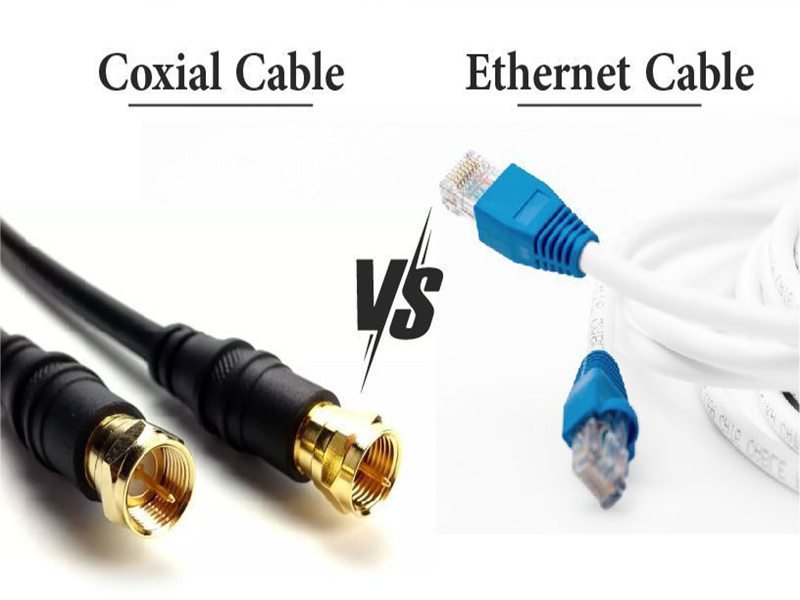
Coaxial cable and Ethernet cable transmit signals differently. Coaxial cable uses a single conductor with shielding and controlled impedance (commonly 50Ω or 75Ω), making it ideal for RF signals, broadband, and video transmission. Ethernet cable uses twisted pairs to transmit digital network data and is optimized for LAN networking with speeds from 100 Mbps to 10 Gbps or more.
Years ago, a customer asked Sino-conn to replace coaxial cables in a monitoring system with Ethernet cables to reduce cost. The result looked fine during lab tests. But once installed near industrial motors, the system began losing data packets. The reason wasn’t the connector — it was the signal environment. That project became a lesson in understanding how these two cable technologies behave differently.
Let’s break it down step by step.
What Is Coaxial Cable?
A coaxial cable is a shielded electrical cable designed to transmit high-frequency signals with stable impedance and minimal electromagnetic interference. It contains a central conductor surrounded by insulation, a metallic shield, and an outer protective jacket. Because the signal and return path share the same axis, coaxial cable maintains stable signal transmission for RF communication, broadband internet, broadcast video, antennas, and test equipment.

Understanding the Structure and Working Principle of Coaxial Cable
Coaxial cable is widely used in telecommunications, RF engineering, broadcasting, and broadband systems because its design minimizes signal loss and protects against interference.
Unlike standard wires, coaxial cable uses a concentric geometry. The signal conductor runs along the center of the cable, while the outer shielding layer surrounds it completely.
This design produces three important benefits:
- Controlled impedance
- Strong EMI shielding
- Stable signal transmission at high frequency
These characteristics make coaxial cable essential for applications where signal quality must remain stable over long distances.
How Is a Coaxial Cable Constructed?
A coaxial cable consists of four main layers. Each layer plays a specific role in signal transmission.
| Layer | Function | Common Materials |
|---|---|---|
| Center conductor | carries the signal | bare copper / tinned copper |
| Dielectric insulation | keeps conductor spacing stable | PE, foam PE, PTFE |
| Shield layer | blocks electromagnetic interference | aluminum foil, copper braid |
| Outer jacket | protects cable from environment | PVC, LSZH, TPU |
The dielectric layer determines the spacing between the conductor and shield. This spacing is critical because it directly controls the cable’s impedance.
The shielding layer prevents external signals from entering the cable and also prevents signal leakage.
Typical shielding coverage ranges from 85% to nearly 100% depending on braid density and foil layers.
What Impedance Does Coaxial Cable Use?
Impedance is one of the most important electrical characteristics of coaxial cable.
The two most common impedance values are 50 ohms and 75 ohms.
| Impedance | Common Applications |
|---|---|
| 50 Ω | RF communication, antennas, radio transmitters, lab equipment |
| 75 Ω | broadcast video, cable television, broadband internet |
Impedance must remain consistent along the entire cable length. If impedance changes, signal reflections occur.
Signal reflections can cause:
- RF power loss
- unstable signal reception
- degraded video quality
- data transmission errors
For RF systems, impedance mismatch is often measured using VSWR (Voltage Standing Wave Ratio).
For digital systems, mismatch can result in packet loss or unstable communication.
What Frequencies Can Coaxial Cable Carry?
Coaxial cable is designed to carry signals across a wide frequency range.
| Frequency Range | Example Application |
|---|---|
| kHz | analog audio systems |
| MHz | broadcast television |
| GHz | wireless communication and radar |
High-performance coaxial cables can operate at frequencies exceeding 18 GHz depending on construction and dielectric material.
Loss increases as frequency increases, so selecting the correct cable type is important for high-frequency systems.
For example:
| Cable Type | Typical Frequency Capability |
|---|---|
| RG58 | up to ~1 GHz |
| RG6 | broadband video systems |
| LMR400 | up to several GHz |
These differences are important when designing RF communication systems.

Where Is Coaxial Cable Commonly Used?
Despite the rise of Ethernet and fiber networks, coaxial cable is still widely used in many industries.
| Industry | Typical Use |
|---|---|
| Telecommunications | cable internet infrastructure |
| Broadcasting | television signal distribution |
| RF engineering | antennas and radio equipment |
| Security systems | CCTV video transmission |
| Test equipment | laboratory signal measurement |
For example, many cable internet networks use coaxial cable to deliver broadband signals to homes.
Even when fiber optic cables carry signals over long distances, coaxial cables often distribute signals locally.
Why Is Coaxial Cable Resistant to Interference?
One of the main advantages of coaxial cable is its resistance to electromagnetic interference.
This protection comes from the cable’s shielding structure.
Typical shielding configurations include:
| Shield Type | Description |
|---|---|
| single braid | basic EMI protection |
| foil + braid | improved shielding |
| double braid | high EMI protection |
Because the shield surrounds the signal conductor completely, external electromagnetic fields have limited influence on the transmitted signal.
This makes coaxial cable reliable in environments such as:
- broadcast studios
- industrial facilities
- telecommunications equipment rooms
- medical imaging systems
What Parameters Do Engineers Check When Selecting Coaxial Cable?
When designing or sourcing coaxial cable assemblies, engineers typically evaluate several technical parameters.
| Parameter | Why It Matters |
|---|---|
| impedance | ensures signal compatibility |
| attenuation | determines signal loss |
| shield coverage | affects EMI protection |
| cable diameter (OD) | affects installation space |
| bend radius | affects flexibility |
| operating temperature | determines environmental durability |
Environmental conditions may also require special jacket materials.
Examples include:
- oil-resistant jackets for industrial machinery
- UV-resistant jackets for outdoor installations
- flame-retardant materials for safety compliance
- halogen-free materials for environmental regulations
Why Many OEM Projects Require Custom Coaxial Cable Assemblies
In many engineering projects, standard cables are not sufficient.
OEM manufacturers often require custom cable assemblies with specific parameters such as:
- custom connector types (SMA, BNC, N-type)
- exact cable length
- specific impedance requirements
- special shielding structures
- high-temperature or chemical-resistant jackets

Manufacturers like Sino-conn typically support this process by providing:
- detailed cable specifications
- engineering drawings (CAD to PDF)
- prototype samples
- full inspection before shipment
This process ensures that the cable assembly meets both mechanical and electrical requirements.
What Is Ethernet Cable?
Ethernet cable is a copper network cable used to transmit digital data between devices such as computers, switches, routers, cameras, and industrial equipment. It uses twisted pairs of conductors and differential signaling to reduce interference. Most Ethernet cables terminate with RJ45 connectors and support speeds ranging from 100 Mbps to 40 Gbps depending on the cable category.

Understanding How Ethernet Cable Works
Ethernet cable is the backbone of modern local area networks (LAN). It connects devices so they can exchange digital data reliably.
Unlike coaxial cable, which carries signals through a single conductor and shield, Ethernet cable uses multiple twisted pairs of copper wires. These twisted pairs transmit signals using differential signaling, where one wire carries the positive signal and the other carries the negative signal.
Because the two signals are equal and opposite, external electromagnetic noise affects both wires equally and cancels out at the receiver. This design allows Ethernet cables to transmit data reliably even in environments with moderate electrical interference.
Typical Ethernet cables contain four twisted pairs (eight conductors total).
| Cable Component | Function |
|---|---|
| Copper conductors | transmit electrical signals |
| Twisted pair structure | reduces electromagnetic interference |
| Separator or spline (in higher categories) | maintains pair spacing |
| Outer jacket | protects cable from mechanical damage |
How Does Ethernet Cable Transmit Data?
Ethernet networks transmit digital information in packets using standardized communication protocols.
Each twisted pair carries signals using balanced differential signaling, which improves noise immunity and allows higher transmission speeds.
Data travels between devices such as:
- computers
- servers
- routers
- switches
- IP cameras
- industrial controllers
Signals are transmitted and received through RJ45 connectors, which are standardized connectors used in most Ethernet networking equipment.
| Parameter | Typical Value |
|---|---|
| number of pairs | 4 pairs |
| conductors | 8 copper wires |
| characteristic impedance | ~100 Ω |
| maximum segment length | 100 meters |
Ethernet cables maintain signal integrity through careful control of pair twisting, conductor spacing, and insulation materials.
What Are the Main Types of Ethernet Cable?
Ethernet cables are categorized according to performance standards defined by international networking specifications.
Each category supports different bandwidth and data speeds.
| Cable Category | Maximum Speed | Bandwidth |
|---|---|---|
| Cat5e | 1 Gbps | 100 MHz |
| Cat6 | 10 Gbps (short distance) | 250 MHz |
| Cat6a | 10 Gbps | 500 MHz |
| Cat7 | 10 Gbps | 600 MHz |
| Cat8 | up to 40 Gbps | 2000 MHz |

Cat5e and Cat6 are widely used in commercial networking.
Cat6a and Cat7 are more common in data centers and high-performance networks.
Cat8 is designed for very high-speed server connections in modern data centers.
What Is the Difference Between UTP and STP Ethernet Cable?
Ethernet cables can be either shielded or unshielded depending on the installation environment.
| Cable Type | Description | Typical Application |
|---|---|---|
| UTP (Unshielded Twisted Pair) | no additional shielding | office networks |
| FTP (Foiled Twisted Pair) | foil shield around pairs | moderate EMI environments |
| STP (Shielded Twisted Pair) | individual pair shielding | industrial networking |
UTP cables are cheaper and easier to install, which makes them popular for office networks.
However, in industrial facilities where electrical noise from motors, power lines, and machinery is common, shielded Ethernet cables provide more reliable performance.
What Connectors Are Used for Ethernet Cable?
The most common Ethernet connector is the RJ45 connector.
RJ45 connectors are standardized connectors that allow Ethernet cables to plug directly into networking equipment.
| Connector Type | Application |
|---|---|
| RJ45 | standard Ethernet networking |
| shielded RJ45 | industrial networks |
| ruggedized RJ45 | harsh environments |
RJ45 connectors typically use 8P8C configuration, meaning eight positions and eight contacts.
Proper connector termination is critical because poor termination can cause signal reflections or crosstalk.
What Distance Can Ethernet Cable Support?
Ethernet networks have a standardized maximum cable length.
| Cable Type | Maximum Length |
|---|---|
| Cat5e | 100 meters |
| Cat6 | 100 meters |
| Cat6a | 100 meters |
| Cat8 | 30 meters (high-speed mode) |
The 100-meter rule exists because signal attenuation increases with distance.
For larger installations such as office buildings or factories, networks often use:
- Ethernet switches
- fiber optic backbone links
- structured cabling systems
This approach allows large networks to maintain high data speeds across long distances.
What Industries Use Ethernet Cable?
Ethernet cable is now the dominant technology for wired digital communication.
It is used in many industries:
| Industry | Application |
|---|---|
| IT infrastructure | office networks |
| manufacturing | industrial automation |
| surveillance systems | IP cameras |
| telecommunications | network equipment |
| data centers | server connectivity |
Industrial Ethernet networks have become increasingly important for smart factories and Industry 4.0 systems.
These systems connect machines, sensors, and controllers into real-time communication networks.
Key Parameters Engineers Check When Selecting Ethernet Cable
When engineers select Ethernet cable for a project, several parameters are evaluated.
| Parameter | Importance |
|---|---|
| cable category | determines speed capability |
| shielding type | affects EMI resistance |
| conductor material | affects signal quality |
| cable diameter | affects flexibility |
| operating temperature | affects reliability |
| flame rating | affects safety compliance |
Environmental conditions may also require specialized cable jackets.
Examples include:
- oil-resistant jackets for factory equipment
- UV-resistant jackets for outdoor installations
- halogen-free materials for safety compliance
- flexible cables for robotic systems
Why Many OEM Products Use Custom Ethernet Cable Assemblies
Standard Ethernet cables are suitable for general networking, but many OEM products require custom cable assemblies.
Examples include:
- industrial automation equipment
- medical devices
- telecommunications hardware
- security monitoring systems
Custom assemblies may require:
| Custom Parameter | Example |
|---|---|
| cable length | precise installation requirements |
| connector type | angled or shielded connectors |
| jacket material | industrial protection |
| shielding level | EMI-sensitive environments |
| labeling | product identification |
Manufacturers such as Sino-conn typically support these projects by providing:
- engineering drawings
- cable specifications
- prototype samples
- full inspection before shipment
This ensures that the cable assembly matches both the electrical design and mechanical layout of the product.
Coaxial Cable vs Ethernet — What Are the Key Differences?
The main difference between coaxial cable and Ethernet cable lies in how they transmit signals and the systems they support. Coaxial cable uses a single conductor with shielding and controlled impedance to carry RF or broadband signals over long distances. Ethernet cable uses twisted pairs of wires to transmit digital network data between devices. Ethernet dominates modern LAN networks, while coaxial cable remains common in RF, broadcast, and broadband infrastructure.
Understanding the Core Differences Between Coaxial and Ethernet Cables
Although both cables transmit electrical signals, they were designed for very different purposes.
Coaxial cable was developed for radio frequency (RF) transmission and broadcast systems, where maintaining consistent impedance and shielding from electromagnetic interference is essential.
Ethernet cable was developed for digital networking, where the priority is transmitting packets of data between devices quickly and reliably.
Because of these design goals, the cables differ in structure, signal behavior, installation method, and typical applications.
How Do Coaxial Cable and Ethernet Handle Signals?
The most important difference lies in how signals travel through the cable.
Coaxial cable uses a single center conductor surrounded by insulation and shielding. The shielding layer acts as the return path for electrical current and isolates the signal from external interference.
Ethernet cable uses twisted pairs of conductors and differential signaling.
| Feature | Coaxial Cable | Ethernet Cable |
|---|---|---|
| Signal path | single center conductor | twisted pair conductors |
| Return path | shielding layer | second conductor in pair |
| Signal type | RF, broadband, video | digital network packets |
| Characteristic impedance | 50Ω or 75Ω | ~100Ω differential |
| Noise control | shielding | pair twisting + differential signaling |
In coaxial cable, electromagnetic fields remain confined inside the cable structure.
In Ethernet cable, signal integrity is maintained through balanced signal pairs and controlled twisting geometry.
Which Cable Provides Better EMI Protection?
Electromagnetic interference (EMI) can degrade signal quality, especially in industrial or broadcast environments.
Coaxial cable is naturally resistant to EMI because of its shielding design.
| Shielding Feature | Coaxial Cable | Ethernet Cable |
|---|---|---|
| shield coverage | often 85–100% | varies by design |
| shield type | braid or foil + braid | optional shielding |
| noise rejection | very strong | moderate to strong |
Ethernet cables may be either unshielded or shielded.
| Ethernet Cable Type | Shielding |
|---|---|
| UTP | no shielding |
| FTP | foil shield |
| STP | shielded pairs |
Unshielded Ethernet cables work well in office environments but may experience interference near motors, transformers, or industrial equipment.
In those environments, shielded Ethernet cables are often used.
Coaxial cable, however, provides consistent shielding performance regardless of environment, which is why it remains popular in RF communication and broadcast systems.
Which Cable Supports Higher Data Speed?
Ethernet cables are designed specifically for digital networking and support higher data speeds in modern LAN systems.
| Cable Type | Maximum Data Rate |
|---|---|
| Cat5e Ethernet | 1 Gbps |
| Cat6 Ethernet | 10 Gbps (short distance) |
| Cat6a Ethernet | 10 Gbps |
| Cat8 Ethernet | up to 40 Gbps |
Coaxial cable can support very high frequencies, but it is typically used for shared broadband transmission rather than device-to-device networking.
For example, cable internet systems deliver high bandwidth over coaxial cable using DOCSIS technology.
| DOCSIS Version | Maximum Downstream Speed |
|---|---|
| DOCSIS 3.0 | ~1 Gbps |
| DOCSIS 3.1 | ~10 Gbps |
| DOCSIS 4.0 | 10+ Gbps |
However, within homes and offices, Ethernet is typically used to distribute data between devices.
How Do Transmission Distances Compare?
Signal distance capability differs between the two cable types.
| Cable Type | Typical Maximum Distance |
|---|---|
| Ethernet copper | 100 meters |
| Coaxial cable | 300–500 meters |
| coaxial with amplifiers | several kilometers |
Ethernet networks follow the 100-meter rule, which ensures reliable data transmission without excessive signal loss.
Coaxial cable can transmit signals over longer distances because the shielding and impedance control reduce attenuation.
This long-distance capability is one reason coaxial cable remains widely used in telecommunications networks.
Which Cable Is Easier to Install and Maintain?
Ethernet networks are generally easier to deploy and maintain.
| Feature | Coaxial Cable | Ethernet Cable |
|---|---|---|
| connectors | BNC, SMA, F-type | RJ45 |
| installation complexity | moderate | simple |
| network structure | bus or point-to-point | star topology |
| troubleshooting | harder | easier |
Older coaxial LAN systems used bus topology, where multiple devices shared the same cable. A single loose connector could disrupt the entire network.
Ethernet networks use star topology, where each device connects independently to a switch. This makes faults easier to isolate and repair.
How Do Typical Applications Differ?
Because of their different designs, the cables are used in different types of systems.
| Application | Coaxial Cable | Ethernet Cable |
|---|---|---|
| cable TV distribution | ✓ | |
| RF antennas | ✓ | |
| broadcast video | ✓ | |
| broadband internet infrastructure | ✓ | |
| computer networks | ✓ | |
| data centers | ✓ | |
| industrial networking | ✓ |
In many modern infrastructures, the two cables actually complement each other.

Example: cable internet network architecture.
| Network Layer | Cable Type |
|---|---|
| ISP backbone | fiber |
| regional distribution | coaxial cable |
| home networking | Ethernet |
Common Mistakes When Choosing Between the Two
Engineers and procurement teams sometimes misunderstand the roles of these cables.
Common mistakes include:
- assuming coaxial cable can replace Ethernet for LAN networking
- assuming Ethernet cable can carry RF signals
- ignoring EMI conditions in industrial environments
- choosing cables based only on price rather than electrical performance
Selecting the wrong cable type can lead to signal instability, network errors, or reduced system reliability.
Which Is Better for Networking — Coaxial Cable or Ethernet?
Ethernet cable is generally better for local area networking because it supports high-speed digital communication, standardized connectors, and simple network architecture. Coaxial cable is still widely used for broadband infrastructure, RF transmission, and broadcast systems. In modern network design, coaxial cable typically delivers signals over long distances, while Ethernet distributes data locally between devices.
Why Ethernet Replaced Coaxial Cable in LAN Networks
During the early development of computer networks in the 1980s and early 1990s, coaxial cable was commonly used in LAN environments. Technologies such as 10BASE2 and 10BASE5 Ethernet relied on coaxial cabling.
However, these systems had several limitations.
| Network Feature | Coaxial LAN (10BASE2) | Twisted Pair Ethernet |
|---|---|---|
| Topology | Bus topology | Star topology |
| Maximum speed | 10 Mbps | Up to 40 Gbps (modern standards) |
| Installation difficulty | High | Low |
| Fault tolerance | Low | High |
In coaxial networks, if a single cable was disconnected or improperly terminated, the entire network could fail.
Ethernet networks based on twisted-pair cables solved this issue by introducing star topology using switches. Each device connects independently to a network switch, making the network more reliable and easier to troubleshoot.
This architectural change played a major role in Ethernet becoming the global standard for LAN networking.
Can Coaxial Cable Still Be Used for Internet?
Yes. In fact, many broadband systems still rely heavily on coaxial cable.
Cable internet providers use coaxial networks built on DOCSIS (Data Over Cable Service Interface Specification) technology.
Typical broadband infrastructure looks like this:
| Network Layer | Transmission Medium |
|---|---|
| ISP backbone | Fiber optic cable |
| Neighborhood distribution | Coaxial cable |
| Home networking | Ethernet or Wi-Fi |
Modern DOCSIS systems are capable of delivering multi-gigabit internet speeds over coaxial infrastructure.
| DOCSIS Version | Maximum Downstream Speed |
|---|---|
| DOCSIS 3.0 | ~1 Gbps |
| DOCSIS 3.1 | ~10 Gbps |
| DOCSIS 4.0 | Up to 10+ Gbps |
Even though Ethernet dominates device networking, coaxial cable remains essential for broadband distribution systems.
How Do Data Distance Limits Compare?
Transmission distance is another key factor when comparing coaxial cable vs Ethernet.
| Cable Type | Typical Distance Without Amplification |
|---|---|
| Ethernet (Cat5e/Cat6) | 100 meters |
| Coaxial cable | 300–500 meters |
| Coaxial with amplifiers | several kilometers |
Ethernet networks must follow the 100-meter rule for copper cabling. Beyond that, switches or fiber connections are required.
Coaxial cable, however, can transmit signals much farther because of its shielded design and impedance control.
This long-distance capability makes coaxial cable suitable for:
- cable TV networks
- broadcast video distribution
- RF antenna systems
- large building signal distribution
How Do You Choose Between Coaxial Cable and Ethernet?
Choosing between coaxial cable and Ethernet depends on the signal type, required bandwidth, installation environment, and transmission distance. Ethernet cables are best for computer networking and high-speed data exchange, while coaxial cables are better suited for RF signals, broadcast systems, and long-distance signal transmission.
Key Technical Parameters to Evaluate
When selecting a cable type for a project, engineers usually examine several parameters.
| Parameter | Coaxial Cable | Ethernet Cable |
|---|---|---|
| Signal type | RF / broadband | digital network data |
| Impedance | 50Ω or 75Ω | 100Ω differential |
| Maximum segment length | hundreds of meters | 100 meters |
| EMI resistance | very strong | moderate to strong |
| Connector types | BNC, SMA, F-type | RJ45 |
For RF or antenna systems, coaxial cable is almost always the correct choice.
For networking devices such as computers, servers, switches, and routers, Ethernet cable is the industry standard.
How Environment Affects Cable Choice
Environmental conditions often determine the correct cable type.
| Environment | Recommended Cable |
|---|---|
| office networking | Ethernet (UTP) |
| industrial automation | shielded Ethernet |
| RF communication systems | coaxial cable |
| broadcast studios | coaxial cable |
| outdoor antenna installations | coaxial cable |
Industrial environments with heavy electromagnetic noise may require shielded Ethernet (STP) or double-shielded coaxial cables.
Factors such as temperature, oil exposure, UV radiation, and chemical corrosion may also require specialized jacket materials.
Which Cable Works Better in Industrial Systems?
Industrial automation systems often combine multiple cable technologies.
Typical example:
| System Function | Cable Type |
|---|---|
| network communication | Ethernet |
| antenna communication | coaxial |
| video monitoring | coaxial |
| machine control network | industrial Ethernet |
In other words, these cables are often complementary rather than competitive.
Selecting the correct cable for each subsystem improves reliability and reduces maintenance costs.
How Do You Customize Coaxial or Ethernet Cable Assemblies?
Custom cable assemblies allow engineers to match cables precisely to system requirements. Customization may include connector type, cable length, shielding level, jacket material, and electrical parameters. Professional cable manufacturers typically provide drawings, specifications, and prototype samples before mass production.
What Can Be Customized in Coaxial Cable Assemblies?
Coaxial cable assemblies can be tailored for specific RF or broadcast applications.
Common customization options include:
| Customization Item | Example Options |
|---|---|
| Connector type | SMA, BNC, N-type |
| Cable impedance | 50Ω or 75Ω |
| Shield structure | braid, foil + braid |
| Cable length | project-specific |
| Jacket material | PVC, LSZH, TPU |
| environmental protection | oil-resistant, UV-resistant |
For antenna systems and RF modules, precise impedance and shielding quality are critical to signal performance.
What Can Be Customized in Ethernet Cable Assemblies?
Ethernet cable assemblies also support many customization options.
| Custom Feature | Example |
|---|---|
| cable category | Cat5e, Cat6, Cat6a |
| connector type | RJ45, shielded RJ45 |
| cable length | custom lengths |
| shielding | UTP, FTP, STP |
| industrial protection | high-temperature jackets |
In industrial systems, cables may require additional features such as flame resistance, oil resistance, and high-flex durability.
How Fast Can Samples and Drawings Be Delivered?
For OEM projects, development speed matters.
A typical engineering workflow includes:
| Step | Process |
|---|---|
| 1 | customer provides model or drawing |
| 2 | manufacturer creates CAD design |
| 3 | engineering review and confirmation |
| 4 | sample production |
| 5 | testing and validation |
At Sino-conn, drawings can usually be prepared within about 3 days, and urgent requests may be completed faster.

Sample production normally takes around two weeks, with urgent samples available in a few days depending on project complexity.
What Certifications Should Cable Assemblies Have?
Many industries require certification and compliance documentation.
Common cable certifications include:
| Certification | Purpose |
|---|---|
| UL | safety standard |
| ISO | quality management |
| RoHS | environmental compliance |
| REACH | chemical safety |
| PFAS declaration | environmental regulation |
These documents are especially important for products exported to Europe, North America, and Japan.
Conclusion: Choosing the Right Cable for Your System
Understanding the difference between coaxial cable vs Ethernet helps engineers and procurement teams design reliable communication systems.
The two cables serve different purposes:
- Coaxial cable excels in RF transmission, broadband infrastructure, and broadcast systems.
- Ethernet cable dominates computer networking and high-speed digital communication.
Rather than replacing each other, they often work together in modern systems.
Many large infrastructures follow this layered approach:
| Network Layer | Cable Type |
|---|---|
| backbone transmission | fiber optic |
| distribution network | coaxial cable |
| local device networking | Ethernet |
Choosing the right cable for each layer ensures stable performance and cost efficiency.
Need Custom Coaxial or Ethernet Cable Assemblies?
If your project requires reliable cable assemblies, Sino-conn can help.
Our engineering team supports customers with:
- detailed cable specifications
- custom connector configurations
- CAD drawings for confirmation
- rapid sample production
- strict quality inspection
- flexible customization for OEM projects
We also support special requirements such as:
- flame-resistant cable jackets
- oil-resistant materials
- UV-resistant outdoor cables
- halogen-free and environmentally compliant materials
Whether you are designing RF equipment, industrial systems, or network devices, the right cable assembly is critical for performance.
If you have a drawing, specification sheet, or even just a product photo, send it to Sino-conn and our engineers will help evaluate the best solution for your project.