Skip to content
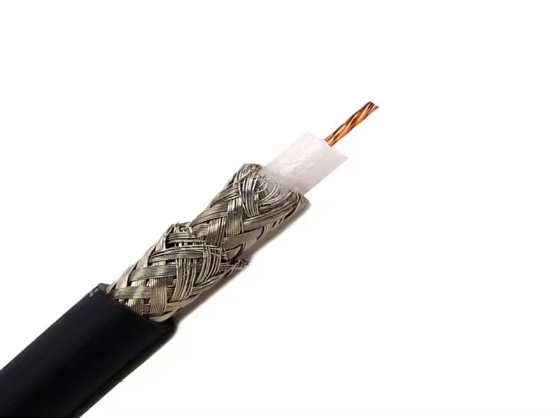
Coaxial cables may look simple — a round wire with a metal tip — yet behind their design lies a world of precision engineering. Every fraction of a millimeter in their structure affects how efficiently signals travel. Whether used in a TV system, radar antenna, or high-speed 5G base station, cable size defines the signal quality, flexibility, and frequency performance.
Coaxial cable sizes describe the cable’s outer diameter, impedance, and conductor geometry, which together determine power handling, signal loss, and flexibility. Common sizes range from micro-coax (OD < 2 mm) for compact electronics to large-diameter cables like RG-213 for high-power RF systems. The correct size depends on application frequency, transmission distance, and environmental factors such as bending and temperature.
Engineers and buyers often underestimate how small size differences change attenuation or connector compatibility. Choosing the right coax size is less about following tradition and more about understanding the physics — how conductor spacing, dielectric materials, and shielding geometry shape performance.
Let’s explore how size, impedance, and construction interact — and how Sino-Conn’s engineering capabilities help customers achieve precise cable performance for any application.
What Determines the Size of a Coaxial Cable?
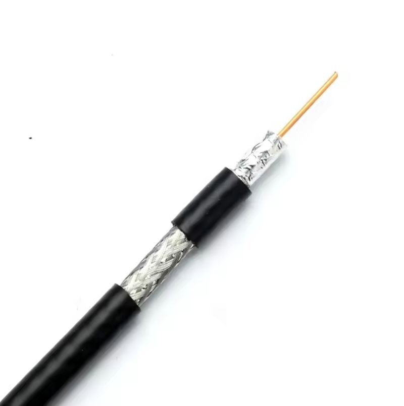
The size of a coaxial cable is determined by the dimensions of its internal components — the center conductor, dielectric insulation, shielding layers, and outer jacket. These physical dimensions, along with the dielectric constant of materials used, directly affect the cable’s impedance, signal attenuation, power capacity, and flexibility. Selecting the correct size means balancing electrical efficiency, frequency performance, and mechanical durability for a given installation or system requirement.
Structural Geometry Defines Electrical Behavior
A coaxial cable’s geometry is its defining feature. The term coaxial refers to the shared axis of the inner conductor and outer shield — an arrangement that ensures uniform impedance and minimal signal loss.
The most influential dimensions are:
- Inner conductor diameter (D₁)
- Inner diameter of the shield (D₂)
- Thickness of the dielectric layer between them
The impedance (Z₀) of a coaxial line is mathematically linked to these dimensions by the equation:
Z₀ = (138 / √εr) × log₁₀(D₂ / D₁)
where εr is the dielectric constant of the insulating material.
- A larger ratio (D₂ / D₁) results in higher impedance.
- A smaller ratio yields lower impedance.
Hence, by adjusting conductor spacing or dielectric thickness, manufacturers can produce 50 Ω, 75 Ω, or other custom impedances without changing materials.
For instance:
- RG-58 (50 Ω) has a relatively thicker center conductor.
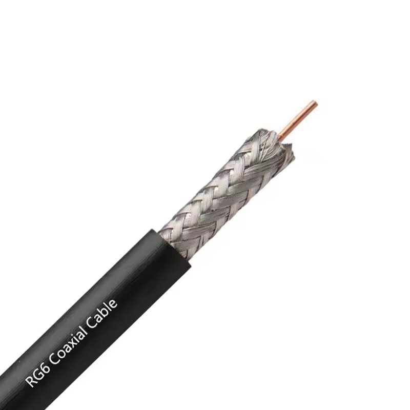
- RG-6 (75 Ω) uses a wider dielectric gap for lower capacitance, optimized for video frequencies.
Dielectric Material Controls Signal Velocity and Size
The dielectric not only sets spacing but also determines how fast signals propagate. Materials with a lower dielectric constant (εr) allow faster signal speed and lower capacitance.
| Dielectric Type | Dielectric Constant (εr) | Temperature Range | Relative Size Impact |
|---|---|---|---|
| Solid Polyethylene (PE) | ~2.3 | −40 °C to +80 °C | Standard |
| Foam PE | ~1.5 | −40 °C to +80 °C | Smaller OD for same impedance |
| PTFE (Teflon) | ~2.1 | −70 °C to +250 °C | Stable under heat |
| Air-spaced | ~1.0–1.1 | Controlled environment | Large OD required |
Because foamed and air-spaced dielectrics provide the same impedance with smaller outer diameters, they’re popular in applications where size reduction and high-frequency performance matter — for instance, in aerospace, test equipment, and miniature sensors.
Shielding Density Impacts Diameter and Flexibility
The shield blocks electromagnetic interference (EMI) and preserves signal integrity. However, it adds both diameter and stiffness.
Common shielding types include:
- Single Braid: 60–80 % coverage; economical and flexible.
- Double Braid: 85–95 % coverage; better EMI rejection.
- Foil + Braid (Dual Shield): Nearly 100 % coverage; used in data/video lines.
- Quad Shield: Two foils + two braids; superior isolation for long-distance or harsh environments.
Increasing shield density enhances performance but also thickens the overall OD and decreases bend radius. For instance, RG-6 Quad Shield is roughly 7.0 mm in diameter versus 6.6 mm for standard RG-6, yet offers up to 40 dB better shielding effectiveness in RF environments.
Outer Jacket Determines Final Diameter and Durability
The outer jacket defines the cable’s mechanical protection, environmental resistance, and handling properties. Its material thickness can vary by 0.2–0.8 mm depending on design and industry standards.
| Jacket Material | Properties | Common Use |
|---|---|---|
| PVC (Polyvinyl Chloride) | Flexible, low-cost, flame-retardant | Indoor, general wiring |
| PE (Polyethylene) | UV-resistant, weatherproof | Outdoor, underground |
| PUR (Polyurethane) | Abrasion and oil-resistant | Industrial robotics |
| FEP / PTFE (Teflon) | High-temperature, chemical resistance | Aerospace, lab, military |
A cable designed for outdoor use may be up to 10–15 % thicker than its indoor equivalent due to extra insulation layers, waterproof tapes, or UV-resistant jackets.
Balancing Size, Power, and Flexibility
In cable engineering, every millimeter counts.
- Larger cables reduce signal loss and support higher power but limit bending.
- Smaller cables bend easily and save space but increase attenuation.
As a rule of thumb:
- Doubling the conductor diameter reduces loss by ≈ 40 %.
- Halving the cable OD increases flexibility by ≈ 60 % but doubles heat dissipation.
Engineers therefore balance size according to installation geometry and frequency response. A data center patch cable might prioritize flexibility, while a radar feed line prioritizes power handling.
Which Coaxial Cable Sizes Are Most Common?
The most common coaxial cable sizes include RG-174, RG-58, RG-59, RG-6, RG-316, and RG-213. Each size has specific impedance, diameter, and performance characteristics that suit different frequencies and applications. Smaller diameters like RG-174 fit compact electronics, while thicker types such as RG-213 or LMR-400 handle higher power and lower attenuation over long distances. Selecting the correct size depends on frequency, connector compatibility, and installation space.
Understanding the “RG” Designation
Most commercial coaxial cables are identified by “RG” numbers, which stand for “Radio Guide”—a term originating from U.S. military specifications in the 1940s. Although the RG system is no longer a formal standard, the designations persist as industry shorthand for describing diameter, impedance, and general construction.
For instance:
- RG-6 commonly refers to a 75-ohm video-grade cable used in television and broadband systems.
- RG-58 usually indicates a 50-ohm general-purpose cable used for data, test, and RF systems.
Each RG type follows a general trend: the larger the number, the smaller the cable diameter, although there are exceptions due to material and manufacturer variations.
The Most Common Coaxial Cable Sizes and Their Applications
Below is a comprehensive comparison chart summarizing the most widely used RG cable types, their dimensions, and performance metrics:
| RG Type | Impedance | Outer Diameter (mm) | Max Frequency | Attenuation (dB/m @ 1 GHz) | Power Capacity (W @ 30 MHz) | Typical Jacket Material | Typical Applications |
|---|---|---|---|---|---|---|---|
| RG-174 | 50 Ω | 2.79 | 1 GHz | ~0.6 | 30 | PVC | GPS, Wi-Fi, IoT devices |
| RG-178 | 50 Ω | 1.8 | 3 GHz | ~1.0 | 15 | PTFE | Aerospace, instrumentation |
| RG-316 | 50 Ω | 2.5 | 6 GHz | ~0.5 | 50 | PTFE | Aerospace, RF testing |
| RG-58 | 50 Ω | 4.95 | 3 GHz | ~0.3 | 150 | PVC or PE | WLAN, test equipment, ham radio |
| RG-59 | 75 Ω | 6.15 | 1 GHz | ~0.22 | 100 | PVC | CCTV, analog video |
| RG-6 | 75 Ω | 6.86 | 2 GHz | ~0.15 | 250 | PE or PVC | TV, broadband, satellite |
| RG-8 / RG-213 | 50 Ω | 10.3 | 15 GHz | ~0.07 | 1000 | PE | Industrial RF, radar, military |
| LMR-195 / LMR-400 | 50 Ω | 4.95 / 10.3 | 6 GHz | 0.17 / 0.07 | 160 / 1000 | PE or FEP | Wireless base stations, antennas |
Small-Diameter Coax Cables (1.5–3 mm OD)
Small coaxial cables such as RG-174, RG-178, and RG-316 are designed for tight-space or lightweight applications.
Key Advantages
- Extremely flexible and lightweight
- Suitable for internal wiring, test fixtures, and mobile equipment
- Available with Teflon jackets for heat and chemical resistance
Use Cases
- RG-174: Used in handheld GPS antennas, short RF jumpers, and portable test gear.
- RG-178: PTFE dielectric and small OD make it ideal for aerospace and instrumentation where space and weight are critical.
- RG-316: A high-performance Teflon version with improved temperature range (–70 °C to +250 °C) and frequency handling up to 6 GHz.
Small cables, however, exhibit higher attenuation—approximately 0.5–1.0 dB per meter at 1 GHz, limiting their use in long-distance runs.
Mid-Size Coax Cables (4–7 mm OD)
This category covers the most widely used general-purpose sizes: RG-58, RG-59, and RG-6.
RG-58 (50 Ω)
- The workhorse for test, radio, and LAN systems.
- Flexible and cost-effective.
- Typical attenuation: 0.25–0.3 dB/m @ 1 GHz.
- Compatible with BNC, SMA, and TNC connectors. Used in RF lab setups, amateur radio, and older Ethernet (10Base2) networks.
RG-59 (75 Ω)
- Common in CCTV, broadcast, and baseband video.
- Slightly thicker than RG-58 with lower capacitance per meter.
- Not ideal for high frequencies above 1 GHz but excellent for video bandwidths.
RG-6 (75 Ω)
- Standard in modern broadband and satellite installations.
- Features foam PE dielectric and dual or quad shielding.
- Low attenuation (~0.15 dB/m @ 1 GHz) allows long runs up to 100 m without amplifiers.
Mid-range cables represent the sweet spot between power, loss, and flexibility — ideal for commercial and residential installations.
Large-Diameter and High-Power Cables (8–12 mm OD)
When performance and low loss outweigh flexibility, engineers use heavy-duty cables such as RG-8, RG-213, or LMR-400.
Key Characteristics
- Thick conductors for higher power (up to 1 kW at 30 MHz).
- Very low loss (0.07 dB/m @ 1 GHz).
- Suitable for long transmission lines and outdoor antenna feeds.
- Often use solid or foamed PE dielectric with high-density copper braids.
These cables are common in radio transmitters, radar systems, military communication, and cell tower installations.
The trade-off: limited bend radius (often >100 mm) and higher cost per meter.
Specialty Coax Cables (Micro-Coax and Semi-Rigid)
Beyond standard RG types, many industries use custom micro-coax or semi-rigid variants for precision systems.
Micro-Coax (≤1.5 mm OD)
Used in consumer electronics and medical imaging, micro-coax cables combine flexibility and miniaturization. They often come in multi-core harnesses for signal transmission in cameras, ultrasound probes, and flexible PCBs.
Semi-Rigid Coax
Constructed with a solid copper tube as the shield, these cables provide exceptional phase stability and shielding. They’re often used in RF modules, aerospace assemblies, and microwave test equipment. Sizes include 0.086″, 0.141″, and 0.250″ outer diameters.
Choosing Between 50-Ohm and 75-Ohm Standards
Cable size correlates strongly with impedance requirements.
- 50 Ω designs (e.g., RG-58, RG-213, LMR-400) are optimized for power transmission and RF equipment.
- 75 Ω designs (e.g., RG-6, RG-59) minimize signal loss for video and data applications.
From a dimensional standpoint, 75-ohm cables have wider dielectric spacing relative to conductor diameter, creating slightly larger ODs for equivalent frequency performance.
Choosing the wrong impedance can lead to mismatched reflections and up to 6 dB signal loss at GHz frequencies.
Environmental and Material Considerations
Environmental conditions can dictate which cable size performs best.
- Outdoor installations (e.g., RG-6 with PE jacket) require UV- and moisture-resistant jackets.
- High-temperature zones favor Teflon-insulated cables like RG-316.
- Industrial applications may specify PUR jackets for oil and abrasion resistance.
Even two cables with identical RG numbers may differ in size if they use different jacket materials or shield densities, making supplier datasheets essential for precise selection.
How Does Coaxial Cable Size Affect Electrical Performance?
Coaxial cable size directly influences signal attenuation, impedance stability, frequency response, and power handling. Larger diameters carry more current and reduce signal loss but limit flexibility. Smaller cables are easier to route but exhibit higher attenuation and reduced power capacity. The correct size balances electrical efficiency, mechanical flexibility, and installation constraints based on system voltage, frequency, and environment.
The Relationship Between Size and Signal Attenuation
Signal attenuation (loss) is the most measurable performance parameter influenced by size.
Loss occurs because of conductor resistance and dielectric absorption. It increases with both frequency and length.
| Cable Type | OD (mm) | Attenuation @ 1 GHz (dB/m) | Typical Application |
|---|---|---|---|
| RG-174 | 2.8 | 0.60 | GPS, IoT, handheld devices |
| RG-58 | 4.95 | 0.30 | Test leads, radios |
| RG-6 | 6.86 | 0.15 | Video & broadband |
| RG-213 | 10.3 | 0.07 | Industrial RF, antennas |
| LMR-400 | 10.3 | 0.065 | Cellular & microwave systems |
As seen above, doubling the outer diameter roughly halves signal loss at 1 GHz.
This is due to larger conductors having lower resistance and better heat dissipation, which improves overall transmission efficiency.
However, this comes at a cost — larger cables are heavier, less flexible, and more expensive to terminate, making them impractical for portable or space-constrained designs.
Power Handling and Heat Dissipation
Power handling capability rises with size because larger conductors can carry more current before overheating.
RF current travels along the surface of the conductor (skin effect), and this effect becomes more pronounced at higher frequencies.
| Cable | Max Power @ 30 MHz | Dielectric Type | Jacket |
|---|---|---|---|
| RG-174 | 30 W | Solid PE | PVC |
| RG-58 | 150 W | Solid PE | PVC |
| RG-213 | 1000 W | Solid PE | PE |
| LMR-400 | 1200 W | Foam PE | PE/FEP |
The dielectric also affects power limits. Foamed PE or PTFE materials withstand higher temperatures and voltages, enabling high-power operation in transmitters and radar systems.
But if the cable is undersized, dielectric heating and conductor loss can cause VSWR drift, noise floor rise, or complete failure in continuous-wave (CW) applications.
Impedance and Size Ratio: Why Geometry Is Critical
The characteristic impedance (Z₀) of a coaxial line is derived from its dimensions:
Z₀ = (138 / √εr) × log₁₀(D₂ / D₁)
where:
- D₁ = diameter of inner conductor
- D₂ = inner diameter of outer shield
- εr = dielectric constant
- 50 Ω systems optimize for maximum power handling (typical for RF, data, and instrumentation).
- 75 Ω systems minimize attenuation (ideal for video, broadband, and high-impedance circuits).
Even slight deviations in D₂/D₁ ratio—caused by manufacturing tolerances or bending stress—can alter impedance by 1–2 Ω, introducing reflections and return loss.
Example:
A coax cable designed for 50 Ω may rise to 52 Ω if its dielectric compresses slightly during bending. At 3 GHz, this mismatch could cause a 1.5:1 VSWR, reflecting roughly 4 % of transmitted power back to the source.
Frequency Response and Cable Diameter
High-frequency performance depends heavily on dielectric uniformity and shield integrity.
Larger cables tend to maintain lower capacitance per unit length and therefore support higher cutoff frequencies.
| Frequency (GHz) | Optimal Cable Diameter | Example Type | Notes |
|---|---|---|---|
| 0.1–1.0 | 3–5 mm | RG-58 | Short RF paths |
| 1–6 | 2–6 mm | RG-316, RG-6 | Test leads, microwave |
| 6–18 | 2–4 mm | Semi-rigid 0.141″ | Low loss, stable phase |
| 18–40 | 0.86–2.2 mm | Micro-coax | Precision measurement |
Smaller coax types (≤2 mm OD) perform well at millimeter-wave frequencies due to reduced skin depth effects, but they carry lower power and require precise connectors such as SMA, SMP, or MMCX.
Conversely, larger RG-213 or LMR-400 cables maintain phase stability up to 10–15 GHz, making them suitable for antenna feedlines and radar systems where distance and loss dominate.
Size vs Flexibility: The Mechanical-Electrical Trade-Off
A larger cable provides superior transmission performance, but mechanical flexibility often dictates final selection.
| Cable Type | Min Bend Radius | Relative Flexibility | Installation Environment |
|---|---|---|---|
| RG-174 | 15 mm | Very flexible | Handheld devices |
| RG-58 | 25 mm | Flexible | Test setups |
| RG-6 | 35 mm | Moderate | Fixed broadband |
| RG-213 | 50–70 mm | Stiff | Outdoor RF lines |
In robotics, instrumentation, or aerospace environments, the ability to route cables through moving joints or confined paths outweighs minimal electrical efficiency.
That’s why smaller ODs, stranded conductors, and braided shields are often prioritized despite slightly higher loss.
For stationary, high-power, or outdoor installations, larger semi-rigid or foam-dielectric cables provide superior electrical stability with minimal maintenance.
Attenuation vs. Frequency Graph
Signal loss scales exponentially with frequency.
An approximate model:
Loss (dB/m) ≈ K × √f
Where K is determined by conductor size, material, and dielectric loss factor.
Example:
At 100 MHz: RG-58 loss ≈ 0.09 dB/m
At 1 GHz: RG-58 loss ≈ 0.30 dB/m
At 3 GHz: RG-58 loss ≈ 0.52 dB/m
Doubling the frequency nearly doubles the attenuation, so engineers choose larger-diameter or low-loss cables (e.g., LMR-400 or RG-213) as system frequencies rise.
Impact of Shielding and Outer Diameter on EMI Performance
Shielding performance also scales with cable size. Larger ODs allow multiple shield layers (foil + braid) or higher braid coverage.
- Smaller cables (RG-174) typically have ~85 % shield coverage.
- Medium cables (RG-6) can achieve >95 % with dual shields.
- High-end cables (LMR-400, RG-400) feature quad shielding with isolation up to >100 dB at 1 GHz.
This improved shielding maintains low transfer impedance (<5 mΩ/m) and protects against both ingress (external EMI) and egress (signal leakage) — vital for sensitive instrumentation and defense electronics.
The Role of Dielectric Constant and Cable Size
Cable size interacts closely with the dielectric constant (εr) of materials:
- A higher εr means slower signal propagation and higher capacitance.
- Larger diameters offset this by reducing electric field density.
Typical velocity factors (Vf):
- RG-174 (PE dielectric): ~0.66 c
- RG-6 (foam PE): ~0.82 c
- RG-316 (PTFE): ~0.70 c
- LMR-400 (foam PE): ~0.85 c
A larger cable using foamed PE can achieve faster signal speed (lower delay per meter), which improves phase matching in antenna arrays or test systems where synchronization is critical.
What Are the Materials and Design Options That Influence Size?
The materials used in a coaxial cable — including the conductor, dielectric, shielding, and jacket — directly determine its size, flexibility, impedance, and durability. Choices such as copper versus aluminum, solid versus foamed insulation, or PVC versus PTFE jackets all affect both diameter and performance. Understanding how each layer interacts allows engineers to design or select cables optimized for electrical efficiency, mechanical handling, and environmental endurance.
Material Science Behind Coaxial Cable Geometry
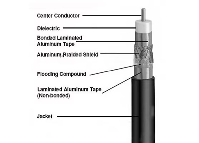
Coaxial cable design is a careful balance of electrical performance and mechanical construction. Each layer contributes differently to overall size and function:
- Inner Conductor — defines resistance, power capacity, and signal transmission.
- Dielectric Insulator — controls impedance, capacitance, and outer diameter.
- Shielding System — provides EMI protection but adds stiffness and thickness.
- Outer Jacket — ensures mechanical protection, flexibility, and environmental resistance.
The specific combination of these materials determines not only how thick or thin a cable is, but also how it behaves under bending, temperature, and frequency stress.
Inner Conductor Materials and Their Impact on Size
The inner conductor carries the RF or signal current. Its material composition and geometry have the most immediate effect on both attenuation and flexibility.
| Conductor Type | Description | Electrical Performance | Effect on Size & Flexibility |
|---|---|---|---|
| Bare Copper (Cu) | Standard high-conductivity core | Excellent conductivity; cost-effective | Moderate stiffness |
| Tinned Copper | Copper coated with tin for corrosion resistance | Slightly higher resistance; better solderability | Similar to bare Cu |
| Silver-Plated Copper | Improved surface conductivity for high-frequency currents | Best skin-effect performance | Typically same diameter; higher cost |
| Copper-Clad Aluminum (CCA) | Lightweight alternative for cost-sensitive designs | 10–20% higher attenuation than pure Cu | Lower density; slightly larger OD required |
| Stranded vs. Solid Core | Multiple small wires vs. single wire | Stranded = flexible, Solid = stable impedance | Stranded increases OD by 5–10% |
Key insight:
Stranded conductors make small cables more flexible, ideal for robotic or mobile systems, while solid conductors maintain precise impedance for test and measurement lines. Manufacturers like Sino-Conn often offer both, depending on customer requirements for mobility versus precision.
Dielectric Material — The Biggest Determinant of Diameter
The dielectric layer separates the inner conductor from the shield and is primarily responsible for controlling impedance (Z₀) and signal velocity. Its thickness and dielectric constant (εr) define both the physical and electrical dimensions of the cable.
| Dielectric Type | Dielectric Constant (εr) | Temperature Range | Relative OD Impact | Common Uses |
|---|---|---|---|---|
| Solid Polyethylene (PE) | 2.3 | −40 °C to +80 °C | Baseline | Standard 50Ω / 75Ω cables |
| Foamed Polyethylene (FPE) | 1.5–1.6 | −40 °C to +85 °C | ~15% smaller OD | Low-loss broadband and RF |
| PTFE (Teflon) | 2.1 | −70 °C to +250 °C | Similar to PE, thinner walls possible | Aerospace, high-temperature |
| FEP (Fluorinated Ethylene Propylene) | 2.2 | −65 °C to +200 °C | Slightly smaller OD | Medical, laboratory |
| Air-Spaced | 1.0–1.1 | Controlled environment | Larger OD | Precision microwave applications |
How Dielectric Affects Size
The lower the dielectric constant, the faster the signal travels (higher velocity factor) — but to maintain impedance, the spacing between conductors must be adjusted.
- A low-εr foam dielectric allows for smaller OD with equivalent electrical properties.
- A solid dielectric increases weight and rigidity but enhances crush resistance.
- Air-spaced designs, used in lab-grade cables, require mechanical spacers, increasing outer diameter while achieving ultra-low loss.
For example, switching from solid PE to foamed PE in a 50 Ω cable can reduce OD by up to 10–15%, saving weight and improving flexibility.
Shielding Type
Shielding protects the internal signal from electromagnetic interference (EMI) and maintains a stable return path.
The number of layers, coverage density, and material type directly affect cable size, flexibility, and cost.
| Shield Type | Coverage | Relative Thickness | Flexibility | EMI Performance |
|---|---|---|---|---|
| Single Braid (Cu) | 60–85% | Thin | High | Moderate |
| Double Braid | 85–95% | Moderate | Medium | High |
| Foil + Braid (Dual Shield) | ≈100% | Moderate | Medium | Very High |
| Quad Shield (Foil + 2 Braids) | >100% | Thick | Low | Excellent |
| Semi-Rigid (Cu Tube) | 100% | Thickest | None | Perfect (Microwave) |
Each layer of braid or foil adds 0.1–0.5 mm to the overall outer diameter.
- Light single-braid shields are used in small cables (RG-174, RG-178) where flexibility is critical.
- Dual or quad shields are applied in RF, telecom, or defense applications demanding 90–120 dB isolation.
This shielding complexity often explains why two cables of identical impedance (e.g., RG-6 and RG-6 Quad) can differ in size by 0.3–0.5 mm.
Outer Jacket
The outer jacket determines how the cable survives physical handling, temperature, UV, and chemical exposure. Its thickness (typically 0.3–1.0 mm) contributes significantly to total diameter.
| Jacket Material | Properties | Size Impact | Common Use |
|---|---|---|---|
| PVC (Polyvinyl Chloride) | Flexible, inexpensive, flame-retardant | Standard | Indoor and general wiring |
| PE (Polyethylene) | Rugged, moisture-resistant | Slightly thicker | Outdoor and buried cables |
| PUR (Polyurethane) | Oil-resistant, abrasion-proof | Slightly thicker | Industrial robotics |
| FEP / PTFE (Teflon) | High-temp, non-flammable, chemical-resistant | Thicker, costly | Aerospace, defense |
| LSZH (Low Smoke Zero Halogen) | Safe for confined spaces | Similar to PVC | Trains, hospitals, data centers |
For instance, replacing PVC with PTFE for a high-temperature environment can increase OD by up to 0.2 mm due to the denser extrusion and thicker mechanical wall required to resist heat deformation.
Jacket choice also affects bend radius and tactile feel — crucial in field applications where technicians frequently move or coil cables.
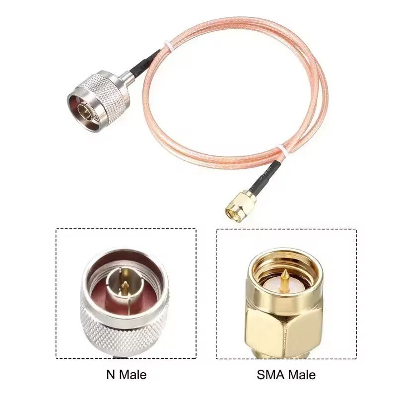
Connector Compatibility and Dimensional Control
Every connector type supports a limited range of cable diameters:
- SMA / SMB: ≤ 5 mm
- BNC / TNC: 4–7 mm
- N-Type / 7-16 DIN: 7–12 mm
Even a minor OD deviation (±0.05 mm) can lead to mechanical mismatch or degraded impedance continuity.
Sino-Conn’s precision extrusion ensures consistent OD tolerance and impedance alignment for custom-engineered assemblies, verified by impedance scanning and mechanical pull tests.
How to Choose the Right Coaxial Cable Size for Your Application
Choose coaxial cable size by balancing frequency, distance, loss budget, power, impedance (50 Ω vs 75 Ω), flexibility, and environment. Larger diameters reduce attenuation and raise power capacity; smaller diameters improve routing and weight. Confirm connector compatibility, minimum bend radius, and jacket/insulation for heat, UV, oil, or flame ratings. Build a quick link-loss and VSWR budget, then select the smallest cable that meets electrical and mechanical limits. Document specs and verify with supplier test data before release.
1) Define Requirements
Start with a concise, quantitative brief.
- Signal type & frequency (f): CW RF, broadband, video, GNSS, microwave, mmWave.
- Run length (L): point-to-point length plus service slack.
- Loss budget (dB): maximum allowable end-to-end attenuation at f.
- Power (W) & duty cycle: average/CW vs burst; ambient temperature.
- Impedance: 50 Ω (RF/power/test) or 75 Ω (video/broadcast).
- Mechanical: available routing space, bend radius, weight limit, repetitive motion.
- Environment: temperature range, UV/water, oil/chemicals, vibration, halogen/LSZH needs.
- Compliance: UL/CSA, RoHS/REACH, flame rating (VW-1/FT-1), PFAS-free options, MIL/IEC if required.
2) Build a Quick Link Budget (Frequency × Distance)
Loss scales with frequency and length. Use manufacturer attenuation tables (dB/m at target f), then add connector/adaptor penalties.
Approximate method:
Total Loss (dB) ≈ (Cable loss @ f) × L + Σ(connector loss)
Example (2 GHz, 5 m):
- RG-58: 0.30 dB/m → 1.5 dB + 0.2 dB (two SMA) ≈ 1.7 dB
- RG-213: 0.07 dB/m → 0.35 dB + 0.2 dB ≈ 0.55 dB
If your system allows ≤1 dB loss, RG-213 (or LMR-400) wins; if ≤2 dB is acceptable and flexibility matters, RG-58 may suffice.
Tip: At higher bands, loss roughly follows √f. Doubling frequency nearly increases loss by ~1.4× for the same cable.
3) Check Power Handling & Temperature
Power rating depends on conductor size, dielectric type, and ambient cooling. Skin effect pushes RF current to the conductor surface; larger conductors dissipate heat better.
| Cable | OD (mm) | Dielectric | Typical Power @ 30 MHz | Notes |
|---|---|---|---|---|
| RG-174 | 2.8 | Solid PE | ~30 W | Short runs, portable |
| RG-58 | 4.95 | Solid PE | ~150 W | General RF/test |
| RG-213 | 10.3 | Solid PE | ~1000 W | Antenna feed lines |
| LMR-400 | 10.3 | Foam PE | ~1200 W | Low loss, outdoor |
De-rate for higher frequency (more heating), tight bundles, high ambient, and continuous duty. For elevated temperatures or duty cycles, prefer foam PE/PTFE dielectrics and larger OD.
4) Choose the Correct Impedance (50 Ω or 75 Ω)
Match system impedance to avoid reflections. A small mismatch causes a voltage standing-wave ratio (VSWR) rise and return loss.
- 50 Ω: radios, test gear, cellular, microwave.
- 75 Ω: broadcast video, CATV, many long-haul low-level signals.
Reflection check (rule-of-thumb):
A 50 Ω system using a 75 Ω cable can introduce VSWR ≳ 1.5:1 at microwave bands—enough to degrade power transfer and noise figure.
5) Balance Size vs Flexibility & Bend Radius
Electrical gains from larger OD must be weighed against routing and motion needs.
| Cable | Min Bend Radius | Flexibility | Use Case |
|---|---|---|---|
| RG-174 | ~15 mm | Very high | Handheld, drones, tight enclosures |
| RG-58 | ~25 mm | High | Racks, benches, short jumpers |
| RG-6 | ~35 mm | Medium | Building runs, broadband |
| RG-213 | 50–70 mm | Low | Outdoor antenna feeds |
Rules:
- Static: ≥10× OD; dynamic: ≥15× OD (or supplier spec).
- For constant motion (robots), choose stranded center and braid-heavy shields; avoid semi-rigid unless phase stability outweighs motion.
6) Verify Connector Compatibility
Every connector series supports specific cable OD and dielectric diameter windows; crimp ferrule and pin sizes must match.
- SMA/SMB: typically ≤5 mm OD (RG-174/316/58).
- BNC/TNC: 4–7 mm (RG-58/59/6).
- N-Type / 7-16 DIN: 7–12 mm (RG-6/11/213/LMR-400).
Undersized or oversized jackets compromise strain relief and can disturb impedance at the termination. Request connector-to-cable matching tables and pull-test data.
7) Select Dielectric, Shield, and Jacket for Environment
Dielectric (affects OD & loss):
- Solid PE: baseline cost and size.
- Foam PE: lower εr → lower loss and potentially smaller OD for a given impedance.
- PTFE/FEP: high-temp (−70 °C to +250 °C), chemical resistance; often slightly thicker jacket.
Shielding (affects OD & EMI):
- Single braid (60–85 %): flexible, compact; moderate isolation.
- Foil + braid: near-100 % coverage; better isolation; moderate OD increase.
- Quad shield: highest isolation; adds 0.3–0.5 mm OD.
- Semi-rigid (Cu tube): perfect shielding/phase; no flexibility.
Jacket (mechanical/chemical/fire):
- PVC: flexible, economical, indoor.
- PE: UV/weather-resistant, outdoor/buried.
- PUR: abrasion/oil resistance, industrial motion.
- LSZH: low smoke/halogen-free for public spaces.
- FEP/PTFE: high temp, chemical, flame.
8) Decision Matrix
| Design Driver | Preferred Choice | Rationale |
|---|---|---|
| Loss ≤0.5 dB over 5 m @ 2 GHz | RG-213 / LMR-400 | ~0.35–0.33 dB + connectors |
| Portable, tight bends | RG-316 / RG-174 | Small OD, stranded, PTFE option |
| CATV/Broadcast | RG-6 / RG-11 (75 Ω) | Low loss/long runs; quad shield optional |
| High temperature | RG-316 (PTFE) | −70 °C…+250 °C, compact |
| Outdoor, UV, moisture | PE-jacketed RG-6 / LMR-400 | Weatherproof, low loss |
| Microwave test stability | Semi-rigid 0.141″ | Phase/stability > flexibility |
Where Are Different Coaxial Cable Sizes Used Across Industries?
Different coaxial cable sizes serve distinct industries based on performance, flexibility, and environmental demands.
Small-diameter cables (≤3 mm) power compact electronics and sensors; mid-size types (4–7 mm) dominate telecom, video, and test systems; large cables (8–12 mm) carry high-power RF for military, aerospace, and industrial uses. Each industry balances attenuation, weight, and durability to achieve optimal performance in its environment.
1. Telecommunications and Networking

Telecom infrastructure depends on low-loss cables for transmitting RF, broadband, and data signals over long distances.
Typical Sizes and Roles
- RG-6 (75 Ω, 6.9 mm OD): Standard for broadband internet, satellite, and CATV connections. Its foam-PE dielectric and quad shielding provide low attenuation (~0.15 dB/m @ 1 GHz) and strong EMI rejection.
- RG-11 (75 Ω, 10 mm OD): Thicker variant for longer outdoor runs up to 300 m with minimal loss.
- LMR-400 (50 Ω, 10 mm OD): Common in cellular base stations, 5G repeaters, and Wi-Fi antennas, combining high power capacity with outdoor-grade PE jackets.
Environmental and Installation Factors
Telecom deployments demand UV-resistant jackets and corrosion-proof connectors (N-type or 7-16 DIN). Larger diameters reduce signal degradation in rooftop, tower, and underground routes, while mid-size RG-6 remains popular inside buildings for cost efficiency.
For flexible jumpers in crowded racks, RG-58 or LMR-195 are preferred to avoid strain on SMA or TNC connectors.
2. Aerospace and Defense
Aerospace and defense systems rely on coaxial cables that maintain precise electrical performance under extreme vibration, altitude, and temperature changes.
Typical Sizes and Materials
- RG-178 / RG-316 (OD ≈ 2–2.5 mm): PTFE or FEP dielectric; used in avionics, radar sensors, and cockpit instrumentation.
- Semi-rigid 0.141″ OD (3.6 mm): Copper-tube shield ensures excellent phase stability for microwave assemblies.
- RG-400 (OD ≈ 5 mm): Dual silver-plated braid and Teflon insulation withstand −70 °C to +200 °C.
Why Size Matters Here
- Small OD cables minimize aircraft weight and route through tight harness bundles.
- Larger 50 Ω designs (e.g., RG-393, LMR-400-FR) are chosen for radar feeds and electronic-warfare subsystems where kilowatt-level RF power must survive continuous vibration.
Sino-Conn and similar OEMs often supply custom PTFE assemblies with strain-relief boots and EMI ferrules to meet MIL-spec performance.
3. Industrial Automation and Robotics
In factories and robotics, coaxial cables transmit control and sensor signals where noise, oil, and motion fatigue are constant concerns.
Common Sizes
- RG-174 (2.8 mm OD): Lightweight, flexible; ideal for robotic end-effectors and vision sensors.
- RG-58 or LMR-195 (5 mm OD): Balance between durability and low loss for PLC, motor-drive, and factory Ethernet/fieldbus links.
- PUR- or PVC-jacketed custom coax (4–7 mm OD): Designed for drag-chain and torsion performance (≥5 million cycles).
Material & Design Focus
- Oil-resistant PUR or TPR jackets prevent swelling.
- Stranded conductors increase bending life.
- Double-braid or foil + braid shields protect against EMI from variable-frequency drives (VFDs) and welding machines.
4. Automotive and Transportation
Modern vehicles integrate RF and high-speed data cables for sensors, cameras, radar, and infotainment.
Typical Sizes
- Micro-coax (≤1.5 mm OD): Used for ADAS radar, LiDAR, and camera systems transmitting up to 6 Gbps.
- RG-174 / RG-188: Short harnesses in dashboards and telematics modules.
- Custom FAKRA/Z-series 50 Ω assemblies: connect in-vehicle networks (GPS, Bluetooth, LTE antennas).
Environmental Considerations
Automotive harnesses must endure −40 °C to +125 °C, humidity, salt spray, and vibration. Jackets are often cross-linked PE or low-smoke halogen-free for safety compliance.
Cable OD directly affects routing feasibility through narrow pillars and headliners; each millimeter saved reduces overall harness weight and cost.
5. Medical and Laboratory Equipment
Healthcare and analytical industries need miniature coaxial lines that maintain signal integrity during sterilization or chemical exposure.
Common Sizes
- Micro-coax bundles (0.3–1.0 mm OD per core): Used in endoscopes, ultrasound probes, and ECG sensors.
- RG-178 (1.8 mm OD, PTFE): Flexible, chemically inert, reusable after autoclaving.
- RG-316 or FEP-jacketed variants: Found in diagnostic imaging and lab automation equipment.

Material Priorities
- FEP or PTFE insulation tolerates sterilizing temperatures and cleaning agents.
- Silver-plated copper conductors ensure stable impedance under bending.
- Low-smoke halogen-free jackets protect patients and staff in clinical environments.
Cable OD is minimized to improve ergonomics and device flexibility; for instance, an ultrasound probe may integrate 20 – 40 micro-coax lines in a 6–8 mm harness.
6. Consumer Electronics and Broadcasting
Coaxial cables are ubiquitous in everyday electronic systems—TVs, set-top boxes, security cameras, and modems.
Typical Sizes
- RG-59 (6.1 mm OD, 75 Ω): Standard for CCTV and analog video.
- RG-6 (6.9 mm OD): Primary choice for digital TV and broadband.
- Mini-RG-59 (4.5 mm OD): Compact option for inter-rack patching or home installations.
Installation Environment
PVC jackets dominate for indoor use; PE or LSZH options appear in wall-mounted or public-venue runs.
Longer cable runs or outdoor feeds upgrade to quad-shield RG-6 to avoid ingress/egress interference.
Connector standards (F-type, BNC, RCA) dictate compatible ODs; installers typically stock crimp ferrules for 4.5–7 mm cables.
7. Research, Testing, and Instrumentation
Precision test benches and laboratory setups require coaxial cables with predictable impedance and phase behavior.
Common Types
- RG-58 / RG-223 (4.95 mm OD): Flexible test leads with BNC/SMA connectors.
- RG-400 (5 mm OD, PTFE): High-temp, dual-shield for oscilloscopes and analyzers.
- Semi-rigid (0.086″–0.250″): Microwave instruments up to 40 GHz; minimal phase drift.
- LMR-240 / LMR-400: Stable for vector network analyzer (VNA) reference paths or antenna calibration.
Performance Needs
- Tight impedance tolerance (±2 Ω)
- Low VSWR (<1.2:1 @ GHz)
- Repeatable bending and connector mating cycles
Here, consistency outweighs raw flexibility; stainless SMA/N-type connectors ensure mechanical stability for repeated test setups.
8. Energy, Oil & Gas, and Mining
Energy and heavy-industry environments require thick, armored, or chemically resistant cables capable of transmitting control or RF monitoring signals in harsh conditions.
Typical Sizes
- RG-213 / LMR-400 (10 mm OD): Long-distance runs in power-plant instrumentation or remote antennas.
- Custom PTFE-insulated 50 Ω cables: Deployed in oil-rig sensor arrays and pipeline monitoring.
- Armored or braided stainless-steel jackets: Protect against abrasion and rodent damage.
Material & Safety Needs
- Flame-retardant, halogen-free jackets for confined spaces.
- Moisture barriers (gel-filled or tape-wrapped) for subsea and mining tunnels.
- Temperature range: −55 °C to +200 °C.
Size and mechanical armor often double OD but guarantee long-term survivability and compliance with safety regulations (UL, IEC 60332).
9. Broadcast, Audio-Visual, and Event Production
Professional broadcast systems depend on 75 Ω cables optimized for video impedance matching.
Typical Sizes
- RG-59 (6 mm): Short patching and CCTV.
- RG-6 / RG-11 (7–10 mm): Long HD-SDI and 4K transmission lines.
- Mini-coax (3–4 mm): Used in multi-core camera snakes to reduce bulk on stage or in studios.
Low-capacitance foam dielectrics and quad shielding ensure loss below 0.2 dB/m @ 1 GHz, critical for preserving color and sync accuracy over long runs.
Conclusion
In electrical and RF systems, size is more than a dimension — it defines signal performance. The right coaxial cable size balances electrical efficiency, flexibility, and environmental endurance. Whether you need micro-coax bundles for medical probes, LMR-grade outdoor jumpers for 5G, or PTFE-insulated test cables for aerospace, Sino-Conn combines precision manufacturing with international compliance. Contact Sino-Conn today to design the right coaxial cable size for your project — one that fits electrically, mechanically, and economically from the very first sample.