 Skip to content
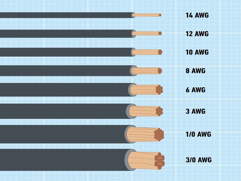
When was the last time you looked at a wire and wondered: Is this the right size for my project? Wire gauge is one of those technical details that seems simple but can make or break a design. From ensuring safe current capacity to preventing voltage drop, knowing how to measure wire gauge is a critical skill for both engineers and buyers.
To measure wire gauge, strip the insulation, measure the conductor’s diameter with calipers or a gauge tool, and convert it to AWG or mm² using a reference chart. For stranded wire, count strands and calculate total cross-sectional area. The correct gauge ensures safe current capacity, reduces voltage drop, and meets certification requirements. Using the wrong gauge can lead to overheating, inefficiency, or compliance failures.
Now, let’s dive into the specifics. But first, imagine this: a procurement team orders USB cables without checking conductor size. The cables look fine, but in testing, laptops fail to charge. Why? The wires were 28 AWG instead of 20 AWG—too thin to carry 5A USB Power Delivery. That single oversight delayed the launch by 6 weeks. That’s why knowing how to measure and specify wire gauge is not just technical—it’s business critical.
What Is Wire Gauge?
Wire gauge describes the thickness of a wire’s conductor, usually expressed in American Wire Gauge (AWG) or mm². It directly impacts how much current the wire can safely carry, how much heat it generates, and how much voltage drop occurs. Choosing the right wire gauge ensures safety, efficiency, and compliance, while the wrong gauge risks overheating or failure.
Understanding Wire Gauge in Real-World Applications
Wire gauge is not just a number on a datasheet—it’s one of the most important design parameters in electrical engineering. It determines whether a USB charging cable powers a laptop reliably, whether automotive harnesses avoid overheating under the hood, or whether medical imaging devices transmit data without interference. Let’s break this down step by step.
What Does AWG Mean Compared to SWG and mm²?
AWG (American Wire Gauge): Used in North America and electronics industries worldwide. It’s a logarithmic scale where smaller numbers mean thicker wires. For example:
- 30 AWG = 0.255 mm diameter
- 12 AWG = 2.05 mm diameter
- 0 AWG = 8.25 mm diameter
SWG (Standard Wire Gauge): Older British system, less common today. A wire labeled “12 SWG” is not the same as “12 AWG,” which often confuses buyers.
mm² (Cross-sectional area in square millimeters): Used in Europe and IEC standards. This is the most intuitive system—larger area = higher ampacity.
Conversion Example:
- 12 AWG ≈ 2.05 mm diameter ≈ 3.3 mm²
- 24 AWG ≈ 0.51 mm diameter ≈ 0.20 mm²
Why the Right Wire Gauge Matters
Wire gauge selection affects:
- Safety: Undersized wires overheat under load, risking insulation melting or even fire.
- Performance: Voltage drop increases as wires get thinner. In USB charging, this can mean a device never reaches fast-charge mode.
- Cost: Oversized wires waste copper and raise costs unnecessarily.
- Compliance: Standards like UL, CE, RoHS, and REACH mandate correct sizing for safe ampacity.
Example: A smartphone cable with 28 AWG power conductors may only support 1.5A charging. A 20 AWG cable supports up to 5A (100W USB-PD). Both may look similar to an untrained buyer—but the performance difference is massive.
Why Does Gauge Affect Current, Heat, and Voltage Drop?
The thinner the wire, the higher its resistance per meter. Resistance generates heat when current flows and reduces delivered voltage.
Resistance of Copper Wires by AWG
| AWG | Resistance (Ω/km) | Max Current (Chassis Wiring) |
|---|---|---|
| 28 | ~65 Ω/km | 1–1.5 A |
| 24 | ~25 Ω/km | 2–3 A |
| 20 | ~10 Ω/km | 5 A |
| 12 | ~1.6 Ω/km | 20 A |
Are Insulation Thickness and Overall OD the Same as Gauge?
A common mistake is assuming thicker cable = thicker conductor. In reality, outer diameter (OD) is affected by:
- Insulation thickness (fire resistance, flexibility).
- Shielding (foil, braid, or both for EMI).
- Fillers and separators (for flexibility and roundness).
Two cables may look identical, but one could have 28 AWG conductors and the other 24 AWG. Only the copper size matters for electrical performance.
Tip: Always ask suppliers for conductor gauge details in datasheets or drawings.
Rule-of-Thumb Checks for Wire Gauge
- Every 3 AWG steps ≈ 2× cross-sectional area.
- 10 AWG ≈ 5 mm²; 13 AWG ≈ 2.5 mm².
- Visual comparison: 12 AWG ≈ thickness of a nickel; 14 AWG ≈ a dime.
While useful for field checks, these shortcuts should always be confirmed with measurement tools (calipers, micrometers).
Wire Gauge vs Applications
| AWG | Cross-Section (mm²) | Typical Applications |
|---|---|---|
| 30 | 0.05 mm² | Signal, sensors, data only |
| 28 | 0.08 mm² | USB 2.0 data, LED control |
| 24 | 0.20 mm² | Standard charging cables |
| 20 | 0.52 mm² | USB-PD 100W, drones |
| 14 | 2.08 mm² | House wiring, lighting |
| 12 | 3.31 mm² | Automotive, industrial |
| 10 | 5.26 mm² | High-power circuits |
Industry-Specific Implications
- Consumer Electronics: Thin wires (28 AWG) are fine for signals, but charging lines must use 24–20 AWG for fast charging.
- Automotive: Harnesses require thicker wires (12–18 AWG) to handle vibrations and higher currents.
- Medical: Even small wires must meet strict EMI and flame-retardant standards.
- Aerospace/Defense: Wires must balance ampacity with weight savings, leading to custom gauges and specialized alloys.
Which Tools Measure Wire Gauge Best?
The best tools for measuring wire gauge include digital calipers and micrometers for precise lab or QC work, wire gauge plates for quick field checks, and laser micrometers or vision systems for industrial production. Multimeters can indirectly measure via resistance per length. The right choice depends on accuracy needs, cost, and application context.
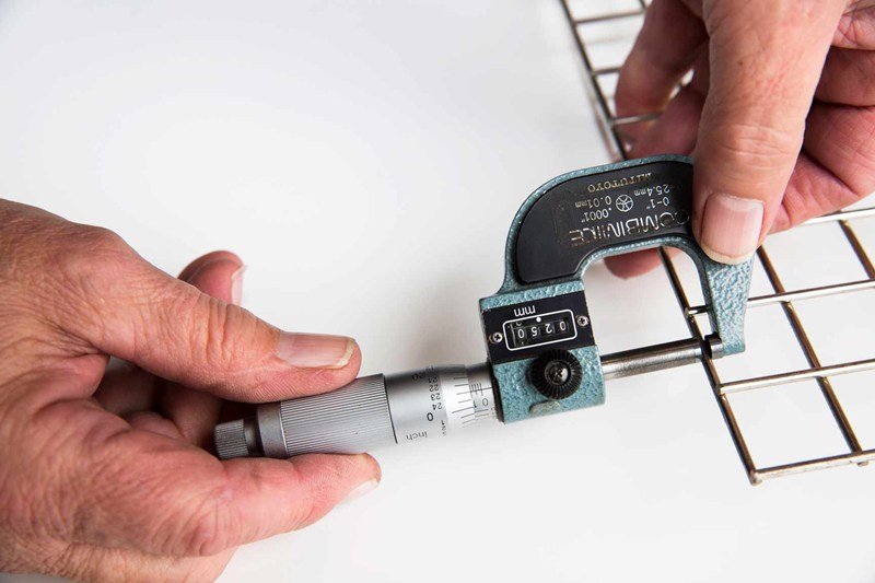
Calipers and Micrometers: Precision Tools for Accuracy
Digital Calipers
- Measure diameter with 0.01 mm resolution.
- Ideal for quick lab checks.
- Easy to use: strip insulation, close jaws, read diameter.
- Cost: Affordable ($30–100).
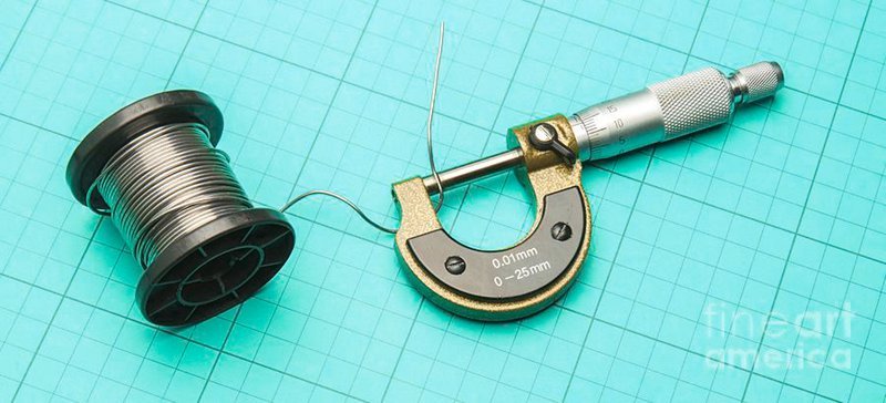
Micrometers
- Higher accuracy than calipers (±0.001 mm).
- Preferred for very thin wires (28–40 AWG).
- Can apply controlled pressure to avoid compressing soft copper strands.
- Cost: Moderate ($50–200).
Example: In USB cable QC, calipers can confirm 28 vs 24 AWG quickly, while micrometers are required for distinguishing 36 vs 38 AWG in fine signal conductors.
Pros: Accurate, affordable, widely available. Cons: Require stripping insulation; manual process is slower for bulk checks.
Wire Gauge Plates or Wheels: Quick Field Tools
- How they work: A metal plate or wheel has pre-cut notches for common wire sizes. Insert stripped conductor into slots until it fits snugly.
- Accuracy: Medium. Good for identifying 10 vs 12 vs 14 AWG, less reliable for <28 AWG.
- Use Case: Electricians on job sites who need “fast and good enough.”
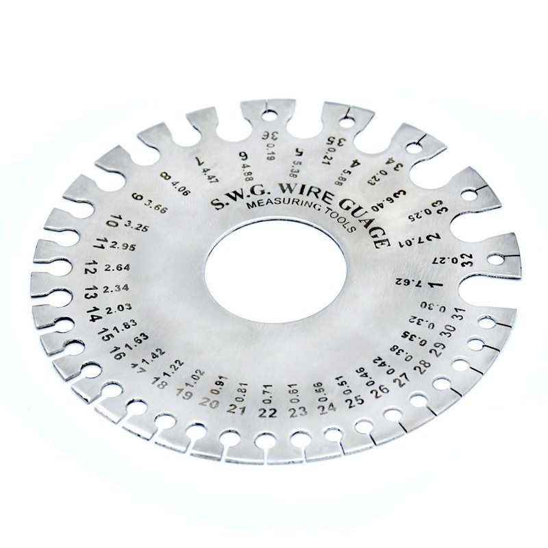
Example: A contractor choosing wiring for an outlet box may use a gauge plate to confirm wires are indeed 12 AWG before connecting to a 20A circuit.
Pros: Inexpensive (<$15), rugged, no batteries. Cons: Not precise; cannot account for stranded packing density.
Laser Micrometers: Industrial Non-Contact Precision
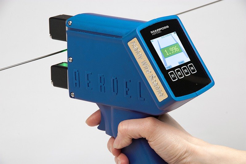
- How they work: A laser beam measures conductor diameter as wire passes through during extrusion.
- Accuracy: Extremely high (±0.001 mm).
- Use Case: Continuous monitoring during manufacturing to guarantee compliance.
- Cost: Expensive ($5,000–20,000+).
Example: Sino-Conn uses laser micrometers in cable production lines to verify conductor diameter continuously, ensuring UL and ISO compliance across every batch.
Pros: Automated, real-time QC, eliminates operator error. Cons: High investment; overkill for small shops.
Vision Systems and Cameras: Multi-Parameter QC
- How they work: Camera-based imaging systems measure not only diameter but also concentricity of insulation, strand uniformity, and defects.
- Use Case: High-end QC for medical, aerospace, or automotive wiring where compliance is non-negotiable.
Example: A medical equipment supplier uses vision inspection to ensure every conductor is uniform, since a single out-of-spec wire could cause compliance rejection.
Multimeters (Resistance per Length): An Indirect Method
- How it works: Measure wire resistance across a known length, compare to AWG reference resistance values.
- Accuracy: Low to medium; depends on copper purity, temperature, and exact length.
- Use Case: When physical measurement isn’t possible (e.g., wires already in harnesses).
Example: A repair technician measures 10m of wire at 0.26Ω. Referring to resistance charts, this aligns with ~22 AWG copper.
Pros: Useful when wire is embedded. Cons: Temperature-sensitive, requires precise length measurement.
Common Mistakes When Measuring Wire Gauge
- Measuring with insulation on: Gives an OD inflated by jacket, fillers, or shielding.
- Using gauge plates on stranded wire: Gaps make results unreliable.
- Assuming OD = gauge: A thickly jacketed 28 AWG cable may look larger than a thinly jacketed 24 AWG.
- Not considering plating: Tin or nickel plating adds negligible thickness; don’t misinterpret it as gauge difference.
Comparison Table: Wire Gauge Measurement Tools
| Tool | Accuracy | Best Use Case | Cost Range | Limitations |
|---|---|---|---|---|
| Digital Caliper | High (±0.01 mm) | Lab/QC, general engineering | $30–100 | Requires stripping |
| Micrometer | Very High (±0.001 mm) | Fine wires, stranded conductors | $50–200 | Slower, delicate |
| Wire Gauge Plate | Medium | Field electricians, quick checks | <$15 | Not for precision |
| Laser Micrometer | Extremely High | Manufacturing QC | $5k–20k | Expensive |
| Vision Systems | Extremely High | Medical, aerospace QC | $10k+ | High cost, complexity |
| Multimeter (Ohms/m) | Low–Medium | Indirect, harness testing | $50–300 | Temp/length sensitive |
Industry-Specific Perspectives
- Consumer Electronics: QC teams rely on calipers and micrometers for sampling, since small AWG differences (28 vs 24) determine charging performance.
- Automotive: Wire harness manufacturers invest in laser micrometers for continuous compliance, ensuring wires survive vibration and heat.
- Medical Devices: Vision systems confirm uniformity, since failures in critical systems (ECG, imaging) are unacceptable.
- Construction: Electricians use gauge plates in the field; “fast enough” trumps absolute accuracy.
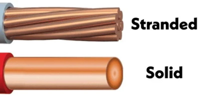
How Do You Measure Solid vs Stranded Conductors?
To measure solid wire, strip insulation and directly measure diameter with calipers or micrometers. For stranded wire, strip, count strands, measure one strand’s diameter, then calculate total cross-sectional area (π × r² × strand count × packing factor). Convert results to AWG or mm² using charts. Always confirm with resistance or supplier datasheets for accuracy.
Measuring Different Conductor Types
Wire measurement sounds simple — until you face solid vs stranded conductors. Solid wires are straightforward: one piece of copper, one measurement. Stranded wires are trickier, with multiple thin strands twisted together, requiring calculation. Both demand care, because even a small miscalculation can cause procurement mistakes, compliance failures, or electrical hazards.
How Do You Strip and Prep a Sample Without Damaging It?
- Solid Wire: Use precision strippers matched to insulation thickness. Avoid knives that may shave off copper. A single nick reduces conductor cross-section and alters measurement.
- Stranded Wire: Strip at least 10–15 mm to expose strands. Avoid twisting or spreading strands before measurement. Strands should remain intact and round.
Common Mistake: Electricians sometimes use pliers or blades to strip — this deforms copper, making measurement unreliable. Sino-Conn’s QC teams use calibrated pneumatic strippers for consistency.
Measuring Solid Wire Diameter Step-by-Step Guide
- Strip ~10 mm of insulation.
- Use calipers or micrometer to measure bare copper diameter.
- Repeat at least 3 points to check for ovality.
- Convert diameter to AWG/mm² using reference charts.
- Confirm by measuring resistance per length (optional).
Example: A solid wire measures 2.05 mm → cross-section ~3.31 mm² → corresponds to 12 AWG.
Why it matters: In automotive wiring, misidentifying 14 AWG (1.63 mm) as 12 AWG (2.05 mm) could undersize a circuit by 25%, risking overheating.
Measuring Stranded Conductors Correctly
Stranded conductors require a little math.
Step 1: Count Strands Carefully separate strands with tweezers. Common configs: 7, 19, 37, 49 strands.
Step 2: Measure One Strand Use a micrometer for accuracy (strands may be <0.1 mm).
Step 3: Calculate Area Total Cross-sectional Area = π × r² × number of strands.
Step 4: Apply Packing Factor (~0.9) Strands don’t pack perfectly; assume ~10% void space.
Step 5: Convert to AWG/mm² Match effective area to chart.
Example:
- 19 strands of 0.12 mm → single strand area = 0.0113 mm² → ×19 = 0.215 mm² → effective area ≈ 0.19 mm² → ~24 AWG.
Packing Factor: Why Stranded Wires Aren’t Perfectly Efficient
Unlike solid wires, stranded wires have gaps between strands.
- Standard round-lay stranded wires: ~90% packing efficiency.
- Compacted or bunched conductors: ~93–95%.
- Flexible “rope lay” wires: as low as 85%.
How to Tell If a Wire Is 10 or 12 Gauge?
This is a common buyer question because these sizes look similar but differ in ampacity.
- 10 AWG: 2.59 mm diameter, ~30 A ampacity.
- 12 AWG: 2.05 mm diameter, ~20 A ampacity.
Visual Rule of Thumb: 10 AWG feels stiffer and is about the thickness of a pencil lead; 12 AWG is closer to a nickel’s thickness.
How Can I Tell If Wire Is 12 or 14 Gauge?
Another frequent question, especially in residential wiring.
- 12 AWG: 2.05 mm diameter, 20 A rating.
- 14 AWG: 1.63 mm diameter, 15 A rating.
The ~0.4 mm difference is hard to eyeball. Best practice: use calipers or gauge plates. Using 14 AWG where 12 AWG is required could cause code violations and safety hazards.
Resistance Method for Cross-Checking
Resistance per meter is a practical backup method, especially if cutting/stripping isn’t possible.
Resistance Values (Copper, 20°C)
| AWG | Resistance (Ω/km) |
|---|---|
| 14 | ~8.3 Ω/km |
| 12 | ~5.2 Ω/km |
| 10 | ~3.3 Ω/km |
| 24 | ~25.7 Ω/km |
| 28 | ~65.3 Ω/km |
Industry-Specific Importance
- Consumer Electronics: Stranded 28 AWG is common for USB data, while 20 AWG is used for PD power. Measuring incorrectly leads to charging complaints.
- Automotive: Harnesses use stranded conductors for flexibility; mislabeling strands could cause overheating under vibration.
- Medical: Fine stranded wires must be measured precisely for EMI compliance; a mis-specified gauge may fail certification.
- Defense/Aerospace: Compact stranded conductors are used for weight savings; precision measurement ensures both performance and safety.
Comparison Table: Solid vs Stranded Measurement
| Type | Method | Accuracy | Challenges |
|---|---|---|---|
| Solid | Strip + measure diameter | High | Ovality, nicking risk |
| Stranded | Count strands + calc area | High–Medium | Counting, packing factor |
| Resistance | Ohms/meter cross-check | Medium | Temp/copper variation |
| Visual | Compare vs coin or tool chart | Low | Easy to misjudge |
How Do You Convert Diameter to AWG and to mm²?
To convert diameter to AWG, measure the conductor’s bare copper diameter and match it to AWG charts or use the logarithmic AWG formula. To convert to mm², calculate cross-sectional area: π × (radius²). For stranded wire, multiply strand area by strand count and apply a ~0.9 packing factor. Reference charts simplify conversions for buyers and engineers.
Converting Wire Size Like a Professional
Wire conversion is one of the most misunderstood topics for buyers. Many assume overall cable thickness equals conductor size, or that AWG and mm² are interchangeable. In reality, AWG is logarithmic, mm² is linear, and conversions require care.
What Is the AWG Formula and When to Use It?
The American Wire Gauge (AWG) system is based on a geometric progression:
Diameter (inch) = 0.005 × 92^((36 – AWG)/39)
Or in mm:
Diameter (mm) = 0.127 × 92^((36 – AWG)/39)
Example:
- For 24 AWG: 0.127 × 92^((36 – 24)/39) ≈ 0.511 mm
- For 12 AWG: 0.127 × 92^((36 – 12)/39) ≈ 2.05 mm
Wire Gauge Reference Table (AWG ↔ mm ↔ mm²)
Conversion Table
| AWG | Diameter (mm) | Cross-Section (mm²) | Resistance (Ω/km, Cu) | Typical Use |
|---|---|---|---|---|
| 30 | 0.255 | 0.05 | 345 | Signal only |
| 28 | 0.321 | 0.08 | 218 | USB 2.0 data |
| 26 | 0.405 | 0.13 | 138 | Ethernet cables |
| 24 | 0.511 | 0.20 | 86 | USB charging |
| 22 | 0.644 | 0.33 | 54 | Automotive low current |
| 20 | 0.812 | 0.52 | 34 | USB-PD 100W |
| 18 | 1.024 | 0.82 | 21 | Lighting circuits |
| 16 | 1.291 | 1.31 | 13 | Extension cords |
| 14 | 1.628 | 2.08 | 8.3 | House wiring |
| 12 | 2.053 | 3.31 | 5.2 | Automotive wiring |
| 10 | 2.588 | 5.26 | 3.3 | High power leads |
Which Quick Rules Convert AWG ↔ mm ↔ mm²?
- Every 6 AWG steps ≈ 4× change in area.
- Every 3 AWG steps ≈ 2× change in area.
- 10 AWG ≈ 5.26 mm² → 13 AWG ≈ ~2.6 mm².
- 20 AWG ≈ 0.52 mm² → 23 AWG ≈ ~0.26 mm².
Rule-of-Thumb Trick: If you forget charts, remember 12 AWG ≈ 2 mm diameter ≈ 3.3 mm². Work up or down from there.
Do Tinned Copper or Aluminum Change Conversion?
- Tinned Copper: The plating adds ~1–2 µm, negligible for gauge. Always base gauge on copper core, not plating.
- CCA (Copper-Clad Aluminum): Same AWG diameter as copper, but higher resistance (about 60% worse). A 24 AWG CCA wire performs more like 26 AWG copper.
- Buyer Warning: Some low-cost suppliers sell CCA wires labeled as copper. Always confirm with resistance per meter tests.
Is Overall Cable OD a Reliable Proxy for Conductor Size?
No. OD includes:
- Insulation thickness
- Shielding (foil/braid)
- Fillers (nylon, cotton)
- Jacket thickness
Example:
- A USB cable with 28 AWG conductors and thick shielding can have the same OD as a 24 AWG cable with light shielding.
- Two cables may look identical but perform very differently.
What Is the Rule of Thumb for Wire Gauges?
- 12 AWG ≈ nickel’s thickness (2.05 mm).
- 14 AWG ≈ dime’s thickness (1.63 mm).
- 18 AWG ≈ paperclip thickness (~1 mm).
- 24 AWG ≈ thin Ethernet strand (~0.5 mm).
Conversion for Stranded Conductors
For stranded wire, conversion needs extra steps:
- Count strands.
- Measure one strand diameter.
- Calculate strand area = π × (r²).
- Multiply by strand count.
- Apply packing factor (0.9).
- Match result to AWG/mm² table.
Example: 19 strands × 0.12 mm diameter → single strand area = 0.0113 mm² → total = 0.215 mm² → effective area = 0.19 mm² → ~24 AWG.
Industry-Specific Use Cases
- USB/Consumer Electronics: 28 AWG for data, 20 AWG for power. Mis-conversion = charging complaints.
- Automotive: 12 AWG vs 14 AWG matters for fuse/circuit compliance.
- Medical: Mislabeling 28 AWG as 26 AWG could fail EMI compliance.
- Aerospace: Weight-critical harnesses require precise mm² specs; overestimation wastes weight budget.
Conversion Table: AWG ↔ mm ↔ mm²
| AWG | Diameter (mm) | Area (mm²) | Ampacity (Chassis, Cu) |
|---|---|---|---|
| 28 | 0.321 | 0.08 | 1.5 A |
| 26 | 0.405 | 0.13 | 2 A |
| 24 | 0.511 | 0.20 | 2–3 A |
| 22 | 0.644 | 0.33 | 4–5 A |
| 20 | 0.812 | 0.52 | 5 A |
| 18 | 1.024 | 0.82 | 7–10 A |
| 16 | 1.291 | 1.31 | 10–13 A |
| 14 | 1.628 | 2.08 | 15–20 A |
| 12 | 2.053 | 3.31 | 20–25 A |
| 10 | 2.588 | 5.26 | 30–35 A |
Do Gauge Choices Impact Ampacity and Voltage Drop?
Yes. Wire gauge directly affects ampacity (current-carrying capacity) and voltage drop (power loss over distance). Thicker wires (lower AWG numbers) carry more current with less resistance and heat. Choosing a wire that’s too thin risks overheating, fire, or device failure. Ampacity and voltage drop must be considered together for safe and efficient design.
What Is Ampacity and How Is It Defined?
Ampacity = Maximum safe current a conductor can carry without exceeding its temperature rating.
Determined by:
- Conductor size (AWG or mm²)
- Conductor material (copper, aluminum, CCA)
- Insulation type (PVC, XLPE, Teflon, LSZH)
- Ambient temperature
- Installation (free air vs conduit, single vs bundled)
Reference: UL, NEC (National Electrical Code), and IEC all publish ampacity charts based on these conditions.
Example:
- 12 AWG copper, THHN insulation: ~20 A continuous.
- 10 AWG copper, THHN insulation: ~30 A continuous.
How Does Wire Gauge Affect Ampacity?
Every 3 steps down in AWG roughly doubles the cross-sectional area of the conductor. Doubling area lowers resistance and allows more current without overheating.
Ampacity Reference Table (Copper, 60 °C, Chassis Wiring)
| AWG | Diameter (mm) | Cross-Section (mm²) | Ampacity (A) | Typical Use |
|---|---|---|---|---|
| 28 | 0.321 | 0.08 | 1.5 | Data signals |
| 24 | 0.511 | 0.20 | 2–3 | USB charging |
| 20 | 0.812 | 0.52 | 5 | USB-PD 100W |
| 14 | 1.628 | 2.08 | 15–20 | House wiring |
| 12 | 2.053 | 3.31 | 20–25 | Automotive harnesses |
| 10 | 2.588 | 5.26 | 30–35 | High-power circuits |
What Is Voltage Drop and Why Does It Matter?
Voltage drop = I × R × length
- I = current (amps)
- R = resistance per meter (Ω/m)
- length = total conductor run (one-way for DC, both ways for AC)
Example:
- A 24 AWG copper wire (25 mΩ/m) carrying 2A over 5 m.
- Voltage drop = 2 × 0.025 × 5 = 0.25 V.
- On a 5 V USB circuit, that’s 5% loss — devices may fail to charge.
Rule of Thumb: Keep voltage drop under 3% for power circuits (NEC).
How Do Run Length and Current Interact?
Two wires of the same gauge may be acceptable at short distances but fail at long runs.
Example:
- A 20 AWG copper wire can carry 5A.
- At 1 m, voltage drop is negligible.
- At 10 m, resistance adds 0.34Ω → drop = 1.7V → load only sees 3.3V from a 5V supply → failure..
Are Derating Factors Needed for Bundled Wires and Heat?
Yes. Wires bundled together in conduit or harnesses cannot dissipate heat as efficiently. NEC and IEC tables apply derating factors:
- 4–6 conductors bundled: reduce ampacity to 80%.
- 7–24 conductors: reduce ampacity to 70%.
- High ambient temperatures (e.g., 60 °C engine bay): further reduce capacity.
Example: A 12 AWG wire rated at 20 A may only be safe for 15 A if bundled in a hot automotive harness.
Industry Examples of Ampacity & Voltage Drop Issues
- Consumer Electronics: Using 28 AWG instead of 20 AWG in USB-C cables causes voltage sag → laptop fails to charge at 100W.
- Automotive: Harnesses undersized by even 2 AWG steps can overheat under vibration → insulation breakdown → safety hazard.
- Medical Devices: Voltage drop in signal lines (e.g., 28 AWG at 5 m) can distort sensitive ECG signals.
- Aerospace: Voltage drop is critical; wires are sized for efficiency while minimizing weight.
Voltage Drop Reference (Copper, 20 °C, 5V circuit, max 3% drop)
| AWG | Current (A) | Max Length (m) | Use Case |
|---|---|---|---|
| 28 | 1.5 | 1.5 | USB 2.0 data |
| 24 | 2 | 4 | Phone charging |
| 20 | 5 | 10 | USB-PD 100W |
| 16 | 10 | 20 | LED strips, lighting |
| 12 | 20 | 30 | Automotive circuits |
| 10 | 30 | 50 | Industrial motors |
Interpretation: If you’re designing a 5V USB harness, 28 AWG works for 1 m, but only 20 AWG works for 5–10 m at 5A charging.
How Do You Specify and Order Custom Cables Correctly?
Specifying custom cables requires defining conductor gauge, strand count, material, plating, shielding, insulation, jacket, OD, bend radius, and certifications. Always confirm compliance (UL, ISO, RoHS, REACH) and request CAD drawings before production. A strong supplier like Sino-Conn offers no MOQ, rapid samples, and 100% QC, ensuring cables meet both design and regulatory requirements.
1. Define Conductor Gauge, Strand Count, Material, and Plating
The conductor is the heart of any cable. Always specify the wire gauge (AWG or mm²), strand count, and strand diameter. For instance, “24 AWG, 19 strands × 0.12 mm” is far more precise than “24 AWG wire.” Material matters as well—pure copper is standard for performance, but tinned copper improves corrosion resistance and solderability. Silver- or nickel-plated conductors may be required in aerospace or medical projects. If this detail is missing, suppliers may substitute inferior copper-clad aluminum (CCA), which drastically increases resistance.
2. Specify Insulation and Dielectric Properties
Insulation not only protects the conductor but also defines electrical performance. Buyers should state insulation material (PVC, XLPE, Teflon, LSZH, halogen-free) and its dielectric strength. For high-frequency or data cables, insulation uniformity ensures impedance control. Temperature rating is another critical factor: XLPE or PTFE can withstand up to 125–200 °C, while PVC is limited to 70–90 °C. Sino-Conn provides datasheets where insulation type, thickness, and temperature limits are clearly listed.
3. Detail Shielding Requirements
Shielding ensures EMI (electromagnetic interference) resistance. State whether you require foil shielding, braided shielding, or both. Foil is cheaper and lighter, but braid provides better coverage against high-frequency noise. Some industries, like medical and defense, require double shielding for compliance. Always specify shield coverage percentage (e.g., 85% braid coverage) to prevent misinterpretation. This detail can make or break compliance with FCC/CE testing.
4. Define Outer Jacket, OD, and Bend Radius
The outer jacket determines durability, flexibility, and compliance. Buyers should specify jacket type: PVC for economy, TPU/TPE for flexibility, LSZH for fire safety, or fluoropolymers for harsh environments. Outer diameter (OD) is equally important—it affects connector termination and routing through enclosures. Bend radius should also be defined for moving cables; for example, robotics may require a bend radius of 7.5× OD instead of the standard 10× OD. These details prevent failures in dynamic applications.
5. State Environmental and Mechanical Requirements
Beyond electrical performance, cables must survive real-world environments. Define whether cables must be flame-retardant, halogen-free, UV-resistant, oil-resistant, waterproof, or abrasion-resistant. For outdoor or automotive applications, UV and oil resistance are essential. In medical environments, cables may need biocompatible or sterilization-safe jackets. By declaring these requirements upfront, buyers avoid receiving cables that look correct but fail under environmental stress. Sino-Conn’s production capabilities cover fire-resistant, high-temperature, halogen-free, and chemical-resistant formulations.
6. Include Certification and Compliance Needs
Compliance is not optional—it’s a gatekeeper for customs clearance and product approvals. Always state the required certifications: UL, ISO9001/14001, RoHS, REACH, PFAS-free, CE, or MIL-SPEC. For North American imports, UL listing is often mandatory. For European projects, RoHS and REACH are critical. Failing to declare certifications can cause shipment delays, regulatory fines, or product recalls. Sino-Conn provides full certification documentation with every order, reducing buyer risk.
7. Request CAD Drawings and Pre-Production Samples
Before production, request CAD drawings to confirm specifications. Sino-Conn provides CAD to PDF drawings within 30 minutes to 3 days, depending on complexity. This ensures all stakeholders (buyers, engineers, and production) agree on parameters before manufacturing begins. Samples are equally critical. Sino-Conn ships urgent samples in 2–3 days, giving engineers time to test mechanical fit, electrical performance, and compliance before committing to mass production.
8. Clarify Order Quantities and MOQ Flexibility
Many suppliers impose high minimum order quantities (MOQs), which prevents small-scale testing. Sino-Conn supports no MOQ—starting from 1 piece. This allows R&D engineers and trade buyers to test prototypes, then scale into mass production when ready. Once validated, Sino-Conn can produce bulk orders with standard lead times of 3–4 weeks, or 2 weeks for urgent projects. MOQ flexibility is critical for startups, custom projects, and niche industries.
9. Communicate Delivery Schedules and Lead Time Expectations
Lead time is often a decisive factor in supplier selection. Buyers should clarify whether they need rapid samples (2–3 days), short-run batches (2 weeks), or bulk production (3–4 weeks). Suppliers like Sino-Conn balance flexibility and scale: urgent projects are prioritized with accelerated production, while large recurring orders benefit from stable lead times. Always align supplier timelines with your project’s product launch or client commitments.
10. Ensure Quality Control and Inspection Standards
Finally, confirm the supplier’s quality control processes. Sino-Conn performs 100% inspection: in-process checks, final product testing, and pre-shipment inspections. Tests include electrical continuity, impedance, resistance per meter, insulation breakdown voltage, and mechanical durability (bending, pull force). Buyers should request QC reports with each shipment. This guarantees that every cable performs as specified, reducing risk of returns or warranty claims.
Conclusion
Wire gauge may seem like a small detail, but it impacts safety, performance, and compliance across every industry—from consumer electronics to medical devices and automotive systems. Measuring wire gauge accurately, converting it correctly, and specifying it clearly ensures your projects stay on time, within budget, and compliant with global standards.
Sino-Conn is more than a manufacturer—we’re a solutions partner. With 18+ years of experience, fast CAD drawings, no MOQ samples, competitive pricing tiers, and a rigorous 100% QC process, we provide custom wire and cable assemblies trusted by global OEMs and trade companies alike.
If you’re ready to eliminate risk, improve reliability, and source cables that meet every technical and regulatory requirement, contact Sino-Conn today,Start your custom inquiry now.


