Skip to content

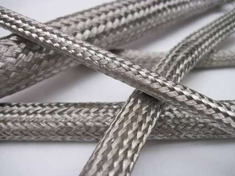
A cable can look heavily shielded on a drawing, use a dense copper braid, and still become the weak point during an EMC test. That catches many development teams off guard because shielding is often treated as a material choice: add foil, specify high braid coverage, and the interference problem should disappear. In real equipment, however, the cable body is only one part of the electromagnetic path. Connector transitions, shield exposure, grounding, installation, frequency, and termination can decide whether the finished assembly actually works.
Cable shield effectiveness describes how well the complete shielding system reduces electromagnetic energy coupling into or out of the conductors. It is commonly evaluated with shielding attenuation or surface transfer impedance, and the result changes with frequency, shield construction, connector continuity, grounding, and termination. A good foil or braid can still perform poorly when the assembly contains gaps, long pigtails, high-impedance shell connections, or an unsuitable ground path.
That is why a statement such as “90% braid coverage” is useful but incomplete. Imagine replacing an ordinary cable with a more expensive double-shielded construction and seeing almost no improvement in the final equipment test. The natural reaction is to blame the cable material. The real issue may be only a few centimeters away, where the braid is opened, twisted into a pigtail, and attached to ground. Understanding shield effectiveness means following that entire current and field path from the cable core to the equipment chassis.

What Is Cable Shield Effectiveness?
Cable shield effectiveness is the ability of a cable shielding system to reduce electromagnetic coupling between the protected conductors and the surrounding environment. It is not determined by shield coverage alone. Frequency, material, geometry, connector continuity, grounding, and termination all influence the final result, so the useful engineering question is not simply whether a cable is shielded, but whether the complete assembly controls the relevant interference mechanism.
What Does Shield Effectiveness Measure?
A cable shield creates a conductive boundary between the signal or power conductors and the electromagnetic environment around them. In practical terms, it has two related jobs. It should reduce external EMI that could couple into sensitive circuits, and it should reduce unwanted energy generated inside the cable from radiating into nearby electronics. Those two directions are closely related, although the dominant coupling mechanism can change with frequency, cable geometry, signal balance, and the way the shield is connected to chassis or ground.
This is not only a concern for precision analog signals. Shielding also matters when a high-speed digital link, switching circuit, servo system, RF path, or poorly balanced differential pair generates common-mode energy. That is why the same subject appears in industrial automation, medical equipment, Ethernet, USB, LVDS, eDP, camera links, RF coaxial assemblies, robotics, machine vision, and test equipment. In each case, the shield is part of a larger return-current and field-control structure rather than a decorative layer around the cable.
The weak point is often not the middle of the cable. A cable may have excellent shielding along 99% of its length, yet energy can enter or escape at the connector transition, a branch breakout, an overmold interface, or a section where the shield was stripped back too far. The best engineering reviews therefore consider the cable shield together with twisting, grounding, routing, ferrites, connector shells, cable length, and power-to-signal separation. That system view is much closer to how EMI behaves in real equipment.
How Does dB Describe Shielding?
Shielding performance is often expressed in decibels because electromagnetic attenuation can span very large ratios. When voltage or field amplitude is compared, a common relationship is SE(dB) = 20 log10(A1/A2), where A1 is the reference amplitude and A2 is the reduced amplitude after shielding. For direct power ratios, the multiplier becomes 10 rather than 20. The mathematics is simple, but the interpretation is only valid when the measured quantities and test conditions are clearly defined.
| Shielding Value | Field or Voltage Ratio | Approximate Amplitude Reduction |
| 20 dB | 10:1 | 90% |
| 40 dB | 100:1 | 99% |
| 60 dB | 1,000:1 | 99.9% |
| 80 dB | 10,000:1 | 99.99% |
The table gives useful intuition, but it does not mean an 80 dB cable will automatically improve a finished device by 80 dB. A result measured on bulk cable with laboratory terminations can differ significantly from the result of a connectorized production assembly. Frequency range, cable length, test fixture, connector condition, grounding method, and shield termination all influence what the number means. For serious supplier comparison, a shielding value should always be read together with the method and frequency band used to obtain it.
Frequency is especially important because cable shielding rarely produces one flat attenuation value from kilohertz through gigahertz. At lower frequencies, shield resistance and magnetic coupling may dominate. At higher frequencies, braid apertures, seams, connector transitions, and termination inductance become more important. A specification that says only “shielding effectiveness greater than 80 dB” is therefore incomplete for many engineering decisions unless it also identifies where and how that performance was measured.
Is Coverage the Same as Effectiveness?
No. Shield coverage describes physical geometry, while shielding effectiveness describes electromagnetic performance. A braid specified at 90% optical coverage means that the woven conductors cover approximately 90% of the underlying cable surface according to the applicable construction method. It does not mean that 90% of electromagnetic interference is blocked, nor does it guarantee a particular attenuation value across the operating frequency range.
Many commercial braided cable designs specify coverage somewhere in the broad 80% to 95% range, although the exact value depends on cable diameter, braid angle, carrier count, wire diameter, flexibility target, and manufacturer. Higher coverage generally reduces open area, which can improve shielding as frequency rises. Even so, two cables with the same nominal coverage can behave differently because braid conductivity, strand size, weave geometry, shield resistance, connector bonding, and termination quality are not necessarily the same.
Foil makes the distinction even clearer. A foil shield can provide almost continuous physical coverage while still becoming ineffective if the foil is cracked by repeated flexing, stops too far from the connector, or relies on a poorly connected drain wire. A useful cable drawing therefore goes beyond a single coverage percentage. It can define shield material, individual-pair or overall shielding, foil overlap where applicable, drain-wire treatment, shield continuity, connector-shell connection, exposed length, and the validation method used to confirm the finished assembly.

How Is Cable Shield Effectiveness Measured?
Cable shield effectiveness can be evaluated through transfer-impedance measurements, shielding-attenuation methods, triaxial testing, current-injection techniques, and complete cable-assembly EMC tests. The correct method depends on the frequency range and failure mechanism. Test results become useful only when sample length, connectors, termination, fixture geometry, grounding, frequency range, measured quantity, and acceptance criteria are stated clearly enough for another engineer to understand what was actually tested.
What Is Transfer Impedance?
Surface transfer impedance is one of the most useful parameters for characterizing cable-shield behavior. It describes how efficiently current flowing on one side of the shield produces unwanted voltage on the protected side. A simplified relationship is ZT = V/(I x L), where ZT is transfer impedance, V is coupled longitudinal voltage, I is shield current, and L is the evaluated cable length. The result is commonly expressed in ohms per meter or milliohms per meter.
In general, lower transfer impedance indicates better shielding for the coupling mechanism represented by that test. This is valuable because it reveals differences that optical coverage cannot show. A visually dense braid can still have less favorable electromagnetic behavior if shield resistance is high, weave geometry increases coupling, or termination introduces significant impedance. Transfer impedance therefore turns the vague statement “this cable is well shielded” into an electrical quantity that can be plotted and compared over frequency.
The frequency curve matters more than a single number. At lower frequencies, the resistive component of the shield can dominate. As frequency increases, inductive effects and coupling through apertures or structural discontinuities become more important. The curve can therefore rise, fall, or change slope over the range of interest. IEC 62153-4-3 is one established reference used for surface-transfer-impedance testing of screened metallic communication cables, but the appropriate method should still be matched to the actual cable type and engineering question.
Transfer impedance should not be treated as the only possible measure of shielding quality. A high-speed digital system may fail because common-mode conversion occurs at a connector transition, while an RF assembly may be limited by leakage or discontinuity around a backshell. In those cases, shielding attenuation, S-parameters, near-field measurements, radiated emissions, current injection, or system-level functional tests may provide information that a single transfer-impedance result cannot capture by itself.
Which Test Method Should Be Used?
The correct method depends on what the cable is expected to do in the real system. Triaxial methods are commonly used for cable screening and transfer-impedance characterization because they create a controlled electromagnetic relationship around the test sample. Other setups can evaluate shielding attenuation, common-mode coupling, or the performance of a connectorized cable assembly. For finished assemblies, connector transitions deserve special attention because a well-shielded cable can lose much of its advantage where the shield is interrupted near the termination.
A practical validation program may start with shield continuity and shield-to-shell continuity, then add more specialized testing only where the application risk justifies it. RF assemblies may use a VNA to examine insertion loss, return loss, VSWR, or other S-parameter behavior. High-speed differential links may use TDR, eye-diagram, BER, packet, or functional system tests. Industrial EMC troubleshooting may combine spectrum measurements, near-field probing, current injection, radiated-emissions testing, or immunity testing with changes to grounding and routing.
No single test belongs on every cable. A low-speed control harness does not need the same validation program as a multi-gigabit camera link, and a static cabinet cable does not need the same mechanical aging as a robotic cable that flexes continuously. SINO-CONN typically treats the test plan as part of the project definition, matching electrical, mechanical, signal, RF, and environmental checks to the actual product risk rather than relying on a generic “100% tested” statement that says little about the relevant performance.
What Makes Test Data Comparable?
Shielding data becomes useful for supplier comparison only when the test conditions are visible. At minimum, the record should identify cable construction, sample length, connectors, shield termination, grounding configuration, frequency range, test fixture, measured parameter, and acceptance limit. If one supplier reports a bulk-cable value while another tests the complete connectorized assembly, the two headline numbers may not represent the same engineering problem even if they are both expressed in decibels.
A curve is often more informative than a marketing maximum because local weaknesses can appear at particular frequencies. Resonances, connector discontinuities, fixture mismatch, or changing shield behavior may create narrow bands of poorer performance that disappear inside a single average or best-case value. Engineers working with EMC-sensitive equipment should therefore ask whether the result is typical or minimum, whether connectors were included, how the shield was bonded, and whether the cable was measured straight, bent, or after flex aging when motion is part of the application.
The most useful test report is not necessarily the one with the largest number. It is the one that allows a design team to reproduce the test logic and understand how closely it matches the final installation. A lower but well-documented result from a representative assembly can be more valuable than a higher value produced under ideal laboratory conditions that the real product cannot reproduce. That distinction becomes especially important during supplier qualification and engineering change reviews.
Which Cable Shield Types Are Most Effective?
No single shield construction is best for every cable assembly. Foil provides near-continuous coverage with low weight, braid offers conductivity and robust termination, served shields favor flexibility, foil-plus-braid combines complementary characteristics, and multiple shields can improve isolation in demanding designs. The best option depends on frequency, motion, cable diameter, connector design, EMC margin, manufacturing complexity, and cost rather than the number of conductive layers alone.
Foil, Braid, and Served Shields
Foil shielding usually consists of aluminum bonded to polyester or another supporting film and wrapped around individual pairs or the complete cable core. Its main advantage is high surface coverage with relatively little increase in diameter or weight. That makes foil attractive for data, instrumentation, internal electronics, and compact assemblies where electric-field or higher-frequency interference is important. The limitation is mechanical durability, particularly in cables that were not designed for repeated flexing.
Braided shielding uses woven copper or tinned-copper strands. It is usually thicker and heavier than foil, but it provides good conductivity, mechanical strength, and a practical surface for circumferential termination to a conductive backshell. Braid is common in industrial control, RF, servo, encoder, robotics, and other applications where the shield must tolerate handling and maintain a reliable low-impedance connection. Openings remain between braid strands, so coverage and weave geometry still influence high-frequency behavior.
Served or spiral shielding wraps conductive strands helically around the cable rather than weaving them. The construction can be very flexible, which is valuable when the assembly experiences frequent movement, but the geometry can open more under bending or torsion. That makes performance more sensitive to mechanical conditions as frequency increases. In a real design, a mechanically suitable served shield can be better than a theoretically stronger but overly stiff braid if the braid degrades or cannot survive the required motion.
| Shield Construction | Main Strength | Main Limitation | Common Engineering Use |
| Foil | Near-continuous coverage, low weight, small OD | Flex fatigue and termination sensitivity | Data, instrumentation, compact electronics |
| Braid | Conductivity, durability, strong 360-degree termination | Larger OD, weight, openings in weave | Industrial, RF, control, motion |
| Served or Spiral | High flexibility | Geometry changes more under motion | Dynamic equipment cables |
| Foil + Braid | Complementary broad-band shielding behavior | Higher cost, OD, and stiffness | Industrial EMI, data, RF |
| Multiple Shield | Higher isolation potential | Manufacturing and termination complexity | Sensitive RF or high-EMI systems |

Does Foil Plus Braid Perform Better?
In many demanding applications, foil-plus-braid is a strong choice because the two shield types address different weaknesses. Foil provides nearly continuous circumferential coverage, while braid adds lower resistance, mechanical reinforcement, and a much better surface for reliable termination. This combination is widely used when the interference spectrum is broad or when the cable needs both high-frequency coverage and a durable ground or chassis connection.
More shielding still brings trade-offs. Foil-plus-braid increases outside diameter, weight, material cost, stripping time, and termination complexity. The cable may also become noticeably stiffer. A second braid or additional foil layer can increase those penalties again. In a compact robot joint, camera gimbal, wearable device, or tight equipment enclosure, the mechanical penalty may create a new reliability problem even if the shield looks stronger on paper.
The practical design sequence is therefore to identify the dominant noise source and frequency, determine whether the main weakness is cable-body coupling or termination leakage, select enough shielding to provide margin, and then confirm that the assembly remains mechanically suitable. If a long pigtail or poor connector shell is the dominant limitation, adding another shield layer to the cable body may produce very little improvement. Good shielding design is usually about finding the weakest link rather than simply adding conductive material.
Which Shield Works Across Frequencies?
Shield behavior changes with frequency because the dominant coupling mechanisms change. At relatively low frequencies, shield resistance, magnetic coupling, cable-loop area, and ground-potential differences can be important. A thin foil layer alone may not solve strong magnetic interference from motors, transformers, or high-current conductors. Twisted pairs, reduced loop area, physical separation, and a better return path can contribute more than simply increasing foil coverage.
At higher frequencies, small openings and inductive discontinuities become much more important. Braid apertures, connector seams, exposed conductors, and pigtail terminations can allow common-mode energy to couple around an otherwise excellent shield. This is one reason combined foil-and-braid designs are common where a broad noise spectrum must be controlled, but the frequency range still needs to be defined rather than assuming the same structure is optimal for every application.
Dynamic motion adds another dimension. A dense braid can perform well in a new, straight sample and then change geometry after repeated bending or torsion. Foil can develop fatigue cracks, and drain-wire or shell contact can change with movement. A dynamic application should therefore evaluate shielding after representative flex exposure whenever EMC performance is critical. The best shield is the one that maintains enough electromagnetic performance through the real mechanical life of the cable, not simply the one with the most impressive new-sample construction.
What Factors Affect Shield Effectiveness?
Shield effectiveness is influenced by frequency, shield resistance, coverage, foil overlap, braid geometry, cable length, connector transitions, grounding, exposed shield length, routing, and mechanical movement. The complete assembly is often limited by its weakest electromagnetic discontinuity, which means premium shield material cannot compensate indefinitely for excessive strip-back, broken continuity, an inductive termination, poor chassis bonding, or routing that places a sensitive cable next to a strong noise source.
Frequency and Geometry
Frequency changes the importance of nearly every shielding detail. At lower frequencies, a shield may behave mainly as a conductive current path, so resistance, ground-potential differences, magnetic coupling, and loop geometry can dominate. At higher frequencies, the same connection must be viewed through inductance, capacitance, aperture size, and electromagnetic field behavior. A physically small gap or short exposed length can become significant when the wavelength becomes shorter and common-mode current finds an easier path around the intended shield.
Differential cables add another issue: balance. Twisted pairs reject external noise because similar interference tends to couple into both conductors and is rejected by the receiver. If the pair is untwisted too far near the connector, if conductor lengths differ, or if the return structure becomes asymmetrical, common-mode conversion can increase. Shielding then has to control energy that a well-balanced pair would otherwise reduce, so EMI and signal integrity become tightly connected around transitions.
Common controlled interfaces illustrate the point. USB differential links often target around 90 ohms, while many LVDS, eDP, MIPI, and Ethernet-style differential systems use nominal targets around 100 ohms; RF coaxial systems commonly use 50 ohms or 75 ohms. Actual values must follow the protocol, connector, PCB, and customer specification. The important lesson is that a shielded high-speed cable is not just a continuity harness. Pair geometry, impedance, return path, shield termination, and connector transition must remain controlled together.
Coverage and Shield Discontinuities
Braid coverage matters because electromagnetic fields can couple through openings, but a single percentage does not describe the whole shielding path. A high-coverage braid can lose much of its advantage if it is opened for several centimeters near a connector and then reduced to a narrow pigtail. In many assemblies, that local discontinuity matters more than the difference between two reasonably high braid-coverage values along the cable body.
Common discontinuities include foil ending before the backshell, braid strands cut during stripping, shield pulled back excessively for easier assembly, a conductive shell connected through a poor interface, a plastic backshell replacing a conductive path, interrupted shielding at a branch point, or a clamp that touches only a small part of the braid. Paint, anodized surfaces, adhesive, oxide, or incorrect hardware can also create unexpectedly high impedance at what appears visually to be a metal-to-metal connection.
These details should be turned into drawing and process requirements rather than left to operator judgment. Practical controls can include maximum shield strip-back, braid preparation method, drain-wire routing, clamp or backshell part number, shield-to-shell connection, permitted pigtail length, and continuity or high-frequency verification where necessary. SINO-CONN’s shield-processing workflow treats those steps as functional EMI controls, because the presence of foil or braid by itself does not prove that the finished assembly has a continuous low-impedance shielding path.
Flexing and Installation
The shielding system must survive the actual installation. A cable bent once during equipment assembly has very different mechanical demands from a robotic cable exposed to repeated bending, torsion, acceleration, and reversal. Under dynamic motion, braid wires can migrate, foil can fatigue, drain-wire contact can change, and stress can concentrate at the connector entry. If the shield degrades mechanically, its electromagnetic behavior can change even though the cable still passes a basic continuity check.
Routing can change EMI performance without changing the cable construction at all. Running a sensitive signal cable parallel and close to motor power, VFD output, relay wiring, or high-current switching conductors increases shared coupling length. Increasing separation, changing route, or crossing noisy and sensitive cables closer to a right angle where practical can reduce coupling. Sharp bends, crushing, and tight clamps can also alter pair geometry and shield shape, affecting both shielding and signal integrity in controlled-impedance assemblies.
A realistic validation plan therefore does not stop with a new straight cable on a laboratory bench. When the application justifies it, the assembly should be evaluated in representative routing, bend radius, motion state, grounding configuration, and operating environment. Troubleshooting becomes much faster when engineers compare noise-source on and off conditions, alternate cable positions, shield connection methods, and known-good samples before deciding that the cable material itself must be changed.
How Do Grounding and Termination Affect Shielding?
Grounding and termination determine how shield current returns to the system. At higher frequencies, short, wide, low-inductance 360-degree bonding generally preserves shielding better than a long narrow pigtail. One-end versus two-end grounding must be chosen according to signal type, frequency, chassis design, isolation, and ground-potential differences. There is no universal rule that can be applied safely to every cable assembly without understanding the equipment architecture.
One End or Both Ends?
The familiar rule “ground the shield at one end” is useful in some systems but becomes misleading when repeated without context. Single-end grounding can help certain low-frequency analog and instrumentation circuits when ground-potential differences would otherwise drive unwanted current through the shield. Breaking the conductive loop can reduce low-frequency hum or measurement error, particularly when the signal system and chassis design were built around that grounding strategy.
High-frequency EMC problems behave differently. The shield needs a low-impedance path for RF common-mode current, and a floating end can become electrically significant as frequency rises. In many industrial, digital, RF, and EMC-sensitive installations, bonding the shield to chassis at both ends provides better high-frequency emissions and immunity behavior when the equipment architecture permits it. The return current then has a much shorter path to the local chassis at each end rather than traveling through a long floating shield section.
Neither method is automatically correct. The decision should consider signal bandwidth, isolation, cable length, equipment grounding, ground-potential difference, safety requirements, connector-shell design, and the intended path for shield current. The drawing should define where the shield terminates and what it bonds to. A production cable should not leave this choice to an installer who may have no visibility into the original EMC design or the frequency range the product needs to control.
360-Degree Termination and Pigtails
A 360-degree termination connects the shield around most or all of its circumference to a conductive backshell, clamp, or chassis interface. The path is short and wide, which keeps inductance relatively low. A pigtail does the opposite: it concentrates shield current into a narrow wire before reaching the ground or chassis point. That wire behaves as an inductor, and its impedance rises with frequency according to XL = 2 pi f L.
The following example uses 100 nH only to show the scale of the effect; actual inductance depends strongly on conductor length, loop geometry, wire placement, return path, and nearby metal. The value is therefore illustrative rather than a specification for every pigtail. Even so, the calculation shows how quickly inductive reactance grows with frequency and explains why a connection that appears electrically harmless in a low-frequency continuity check can become the dominant shield limitation in an RF or EMC test.
| Frequency | Reactance of 100 nH Illustrative Pigtail |
| 100 kHz | 0.063 ohm |
| 1 MHz | 0.63 ohm |
| 10 MHz | 6.28 ohms |
| 100 MHz | 62.8 ohms |
At 100 kHz, the additional impedance may be modest in many systems. At 100 MHz, the same illustrative connection produces tens of ohms of inductive reactance. That is enough to explain how an excellent braid can still perform poorly in a high-frequency emissions or immunity test. Pigtails remain practical in some lower-frequency or installation-specific designs, but they should be treated as electrical components with frequency-dependent behavior rather than as zero-impedance ground connections.
Drain Wire and Connector Shells
A drain wire is primarily a convenient electrical connection to a foil shield and should not be treated as an unused spare conductor. The cable drawing should state exactly how it is terminated, whether at one end, both ends, chassis, connector shell, or another project-specific reference. Leaving that detail ambiguous can produce assemblies that look identical externally but behave differently because installers or operators choose different grounding points.
For high-frequency applications, the drain wire should not automatically become the only shield path. Where the connector system permits it, a direct circumferential connection between the braid or conductive shield structure and a metal backshell usually creates a lower-inductance path. The connector shell then becomes part of the electromagnetic enclosure, carrying the shielding boundary through the interconnect instead of forcing current to jump across an exposed transition.
Production inspection should therefore include more than visual confirmation that a drain wire exists. Useful controls can include shield-to-shell continuity, braid contact area, clamp position, shield exposure, shell plating or surface condition, and correct termination hardware. Paint, oxide, plastic, adhesive, or a poorly seated clamp can interrupt a connection that appears mechanically secure. A premium shield material cannot compensate for a connector interface that was never treated as an electrical part of the shielding design.
How Do You Select and Validate Cable Shielding?
Select cable shielding by defining the signal, interference source, frequency range, cable length, routing, motion, connector, grounding architecture, and EMC requirement before choosing material. Then select shield construction and termination together, validate the complete connectorized prototype under realistic conditions, and freeze the successful configuration in controlled drawings, BOMs, work instructions, inspection criteria, and production tests so later batches reproduce the approved electromagnetic behavior.
Define the Real EMI Environment
Starting with “we need a shielded cable” is too vague for reliable engineering. The manufacturer needs to understand what the shield is expected to control. The interference source may be a VFD, servo motor, switching power supply, relay, inverter, RF transmitter, high-current conductor, or neighboring digital channel. The affected circuit may be analog instrumentation, an encoder, camera link, RF receiver, Ethernet channel, USB interface, or another sensitive path with very different susceptibility.
Useful project inputs include protocol or signal type, data rate or frequency, voltage and current, cable length, noise source, routing near power wiring, connector part numbers, equipment chassis design, grounding, static or dynamic use, bend radius, temperature, environment, and the applicable EMC target. Existing failure information is also valuable. A spectrum plot, failed EMC report, packet-error log, image artifact, or description of the operating condition can narrow the problem much faster than simply requesting “stronger shielding.”
These inputs often reveal that the shield is only part of the solution. Adding a heavier braid may not fix EMI if a differential pair is untwisted too far at the connector. Changing to foil-plus-braid may have little effect if a long pigtail remains the dominant high-frequency impedance. A ferrite may suppress one band while doing little elsewhere. The most efficient path is to define the interference mechanism first and then decide which combination of shielding, grounding, pair geometry, routing, and filtering addresses it.
Validate the Complete Prototype
Prototype testing should reproduce the condition the design is intended to control. A basic low-speed cable may need continuity, insulation, shield continuity, mechanical inspection, and functional testing. A higher-risk assembly may require shield-to-shell checks, spectrum measurements, near-field probing, radiated-emissions or immunity testing, TDR, VNA measurements, insertion loss, return loss, VSWR, BER, eye-diagram analysis, network testing, or system-level functional validation under representative noise conditions.
The important principle is to match the test to the risk. Continuity proves that an electrical path exists, but it cannot prove that an RF shield has acceptable high-frequency performance. A strong VNA result does not prove that the assembly survives the required bending or vibration environment. A new cable that passes EMC on a straight bench setup may behave differently after flexing or when routed next to the actual motor drive inside the final machine.
SINO-CONN’s engineering process typically links the validation plan to the project stage and failure mode. Electrical, mechanical, signal, RF, and environmental checks are selected according to the interface and application, and the approved sample becomes more useful when its test condition is documented. If a customer already has a failed assembly, providing both a failed sample and a known-good reference can significantly speed diagnosis because differences in termination, material, geometry, and routing can be compared directly.
Control the Approved Construction
Once a prototype works, the challenge changes from design to repeatability. The successful shield configuration should be turned into production data rather than remaining only in an engineer’s notes. Depending on the assembly, controlled fields may include shield material, braid or foil construction, coverage requirement, foil overlap, drain wire, strip-back dimension, maximum exposed length, connector-shell connection, backshell or clamp part number, permitted pigtail length, grounding destination, overmold geometry, and required inspection or electrical checks.
Production controls should focus on the small details that can change electromagnetic performance between batches. Typical risks include excessive shield removal, cut braid strands, loose braid bundles, drain-wire misconnection, strands causing shorts, incomplete shell contact, wrong clamps or backshells, unapproved material substitutions, and changes in exposed length. These features are easy to overlook if final inspection is focused only on pinout, appearance, and basic continuity.
A robust manufacturing baseline connects the approved drawing, BOM, pinout, work instruction, inspection points, test method, and sample revision. SINO-CONN uses that type of controlled project workflow to carry engineering requirements from prototype through pilot and repeat production. For an existing EMC problem, the fastest starting package is usually a drawing or sample, connector part numbers, shield and ground schematic, cable routing, interference source, operating frequency or protocol, and whatever test evidence already exists. That gives the engineering team enough context to determine whether the real constraint is shield material, termination, grounding, connector continuity, routing, or several of them together.
Cable shield effectiveness is ultimately a property of the complete electromagnetic path, not a label printed on a cable datasheet. A strong braid or foil layer is valuable, but it cannot compensate indefinitely for an open connector transition, an inductive pigtail, poor chassis bonding, a shield that fatigues in motion, or a route that places a sensitive signal beside a strong noise source. The most reliable approach is to define the interference environment first, select shielding and termination together, validate the connectorized assembly in representative conditions, and then control the construction details that made the prototype work. When those steps are handled as one engineering process, shielding becomes measurable and repeatable instead of a trial-and-error material upgrade.
Frequently Asked Questions
What is a good cable shielding effectiveness in dB?
There is no single dB value that is “good” for every cable because the required attenuation depends on frequency, test method, interference level, equipment susceptibility, connector design, and the amount of EMC margin available in the system. Values such as 40 dB, 60 dB, or 80 dB may all be useful in different contexts, but they should only be compared when the measurement conditions are similar. For engineering approval, the frequency range and complete cable-and-connector test configuration matter more than a standalone headline value.
Is 90% braid coverage enough for EMI shielding?
A 90% braid-coverage specification can be a reasonable construction target, but it does not prove that the finished cable assembly will meet an EMI requirement. Coverage influences open area in the braid, while electromagnetic performance also depends on shield conductivity, braid geometry, frequency, connector continuity, exposed length, and termination. A cable with somewhat lower coverage but an excellent 360-degree shell connection can outperform a high-coverage braid terminated through a long pigtail. Coverage should therefore be treated as one controlled design parameter rather than the final shielding specification.
Is foil shielding better than braided shielding?
Neither is universally better. Foil provides near-continuous coverage with low weight and small diameter, which can be attractive for data, instrumentation, and compact electronics. Braid usually offers lower resistance, greater mechanical durability, and a better surface for circumferential connector termination. Foil-plus-braid constructions combine the two when broader performance is needed, but they also increase diameter, stiffness, cost, and assembly complexity. The correct choice depends on frequency, movement, connector design, routing, and the actual EMI mechanism the cable must control.
Should a cable shield be grounded at one end or both ends?
Single-end grounding can be useful in some low-frequency analog or instrumentation systems when ground-potential differences would otherwise create unwanted shield current. High-frequency EMC often benefits from low-impedance chassis bonding at both ends when the equipment architecture allows it, because RF current needs a short return path. Neither method is a universal rule. Signal bandwidth, isolation, cable length, chassis design, safety requirements, and ground-potential differences should be reviewed before the grounding strategy is fixed in the cable drawing or installation instructions.
Why does a shielded cable still have EMI problems?
A shielded cable can still have EMI problems when the dominant leakage path is not the cable body. Common causes include excessive shield strip-back, long pigtail grounding, poor connector-shell continuity, incorrect chassis bonding, broken foil or braid, pair imbalance, routing near motors or VFD output, and a shield construction that does not match the relevant frequency range. The fastest troubleshooting method is usually to compare cable position, grounding, termination, and known-good samples while reproducing the actual operating condition rather than immediately replacing the cable with a heavier shield.
How can cable shield effectiveness be tested after assembly?
A finished assembly can be checked at several levels depending on risk. Basic production checks include shield continuity and shield-to-shell continuity. More demanding projects can use transfer-impedance or shielding-attenuation methods, current injection, spectrum or near-field measurements, radiated EMC testing, TDR, VNA measurements, or system-level functional tests such as BER, packet performance, image quality, or RF response. The best test is the one that reproduces the failure mechanism and includes the real connector and termination geometry rather than evaluating only an ideal section of bulk cable.