 Skip to content
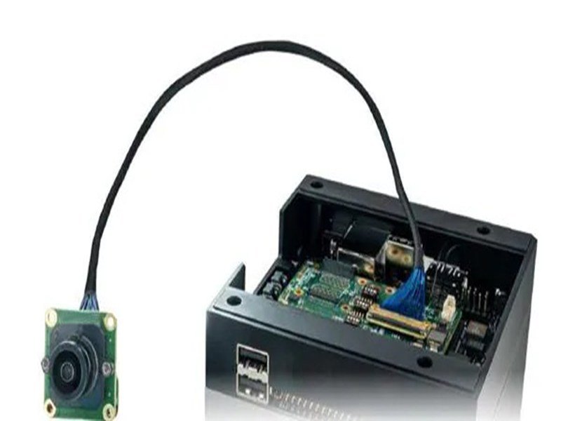
Micro coax looks simple until a product team tries to fit dozens of high-speed signal paths through a hinge, camera head, medical probe, display housing, or compact embedded device. The cable may be smaller than a millimeter in outside diameter, yet its center conductor, dielectric, shield, jacket, connector transition, and grounding path all have to work together. That is where construction stops being a drawing of four concentric circles and becomes a real engineering decision involving signal performance, routing space, flexibility, process capability, and long-term reliability.
A micro coaxial cable is built around a center conductor surrounded by dielectric insulation, an outer conductive shield, and a protective jacket. This concentric structure creates a controlled signal path in a very small space. In a finished assembly, conductor gauge, cable diameter, dielectric material, shield design, bend geometry, connector transition, termination length, and grounding also influence impedance, loss, EMI performance, flexibility, and durability.
The practical lesson is easy to miss: the smallest cable is not automatically the best cable, and a cable with the correct nominal impedance is not automatically a good finished assembly. A 46 AWG design may save valuable space compared with 40 AWG, but it also creates higher conductor resistance and a much tighter stripping and termination window. Likewise, a well-made cable can lose signal margin if too much shield is opened at the connector. The rest of this guide follows the signal from the copper in the center to the connector on the board, showing where construction choices matter and what should be checked before a design is frozen for production.

What Is Micro Coax Construction?
Micro coax construction is the concentric arrangement of a center conductor, dielectric, outer conductor or shield, and protective jacket within a miniature cable. The structure is designed to carry high-speed or high-frequency signals in very limited space while controlling impedance, electromagnetic interference, flexibility, and mechanical reliability. In finished assemblies, connector transitions, grounding, bundling, and termination geometry become part of the practical construction as well.
What Makes Micro Coax Different?
The electrical principle is the same as standard coax, but miniaturization changes almost every manufacturing and design trade-off. Conventional coax used for antennas, test equipment, or external RF links often has an outside diameter of several millimeters. Micro coax used inside cameras, displays, medical equipment, robotics, and compact electronics can be well below 1 mm, depending on the cable family and performance target. That reduction makes dense routing possible, but it also means the conductor, dielectric, shield, and jacket are all thinner and more sensitive to process variation.
At this scale, a small nick in the conductor can remove a meaningful percentage of its cross-section, and an inconsistent shield opening can represent a large portion of the connector transition. A bend that looks harmless on a larger cable may deform a micro coax enough to change local geometry. This is why micro coax is not simply “tiny coax.” It is a transmission-line structure with very little mechanical margin. SINO-CONN’s documented product scope includes fine 46/48/50 AWG micro coax, multi-coax bundles, high-density board connections, LVDS/eDP/MIPI configurations, RF micro coax, and hybrid assemblies, all of which depend on precise control of routing and termination rather than cable diameter alone.
Why Is Coaxial Geometry Used?
Coaxial geometry keeps the signal conductor and its return path in a controlled physical relationship. The center conductor carries the signal, the dielectric fixes the spacing and electrical environment around it, and the surrounding conductive layer provides the return path while helping contain electromagnetic fields. This arrangement is useful when edge rates or frequencies become high enough that an interconnect must be treated as a transmission line rather than as an ordinary piece of wire. The geometry is therefore doing electrical work even though most of it is hidden under the jacket.
The key point is that the layers cannot be selected independently. Reducing conductor diameter increases DC resistance. Changing dielectric thickness or dielectric constant changes impedance and capacitance. Changing shield diameter changes the electromagnetic field geometry. Opening the shield near a connector alters the return path, and a connector can introduce its own discontinuity. For many micro-coax channels, 50 ohms single-ended is a common industry reference, while differential systems may target values such as 90 or 100 ohms depending on the protocol. Those numbers are starting points, not universal rules, and the actual assembly requirement must come from the system specification.
Where Is Micro Coax Used?
Micro coax becomes particularly useful when a product has several constraints at the same time: limited Z-height, high channel density, EMI sensitivity, controlled signal behavior, and a routing path that must bend or fold through three-dimensional space. Common examples include camera modules, LCD and OLED displays, medical imaging equipment, ultrasound systems, industrial vision, robotic heads, UAV and gimbal cameras, AR/VR devices, and compact embedded computing platforms. In these products, the interconnect often has to disappear into a space that ordinary shielded wire simply cannot use efficiently.
A display hinge is a good example because the electrical and mechanical requirements compete directly. The design may need dozens of signal paths between the main board and display while preserving a narrow hinge, predictable folding behavior, and low visual bulk. A conventional bundle of larger shielded cables may become too thick, while an FFC or FPC may not offer the same three-dimensional routing freedom. Micro coax can solve that combination, but it is not automatically the right choice for every circuit. Low-speed control lines, power conductors, or generous routing spaces may be served more economically by other cable structures.

What Are the Main Cable Layers?
A micro coaxial cable normally contains four functional layers: center conductor, dielectric, outer conductor or shield, and outer jacket. Each layer contributes to electrical performance and mechanical behavior. The final result depends on material, thickness, concentricity, and dimensional stability, which is why two cables with the same AWG can still differ significantly in impedance, capacitance, attenuation, flexibility, stripping behavior, and durability.
What Does the Center Conductor Do?
The center conductor carries the electrical signal, but its size also affects resistance, flexibility, termination strength, and overall cable diameter. As AWG becomes finer, conductor cross-sectional area falls quickly. That makes it possible to reduce cable OD and increase channel density, but the trade-off is higher resistance per meter and a smaller mechanical section that is easier to damage during stripping or repeated bending. For short internal high-speed links, the higher DC resistance may be acceptable because signal current is small and length is limited, but it still affects loss and process robustness.
The following values are theoretical copper references based on nominal AWG dimensions at approximately 20 degrees C. Actual micro-coax products may use stranded conductors, plating, alloys, or proprietary constructions, so production design should rely on the cable manufacturer’s datasheet and measured assembly performance rather than these numbers alone. The table is most useful for showing how quickly conductor area falls as AWG becomes finer and why a move from 40 AWG to 46 or 50 AWG is a meaningful engineering change rather than a minor packaging adjustment.
| AWG | Nominal Copper Area | Approx. Solid Diameter | Theoretical Copper Resistance at 20 C |
| 36 | 0.0127 mm² | 0.127 mm | ~1.36 ohm/m |
| 38 | 0.0080 mm² | 0.102 mm | ~2.15 ohm/m |
| 40 | 0.0050 mm² | 0.080 mm | ~3.44 ohm/m |
| 42 | 0.0032 mm² | 0.063 mm | ~5.4 ohm/m |
| 44 | 0.0020 mm² | 0.050 mm | ~8.6 ohm/m |
| 46 | 0.00125 mm² | 0.040 mm | ~13.8 ohm/m |
| 48 | 0.00079 mm² | 0.032 mm | ~21.8 ohm/m |
| 50 | 0.00050 mm² | 0.025 mm | ~34.5 ohm/m |
What Does the Dielectric Do?
The dielectric electrically separates the center conductor from the outer conductor while holding the geometry that helps establish characteristic impedance. It is not simply insulation. Its dielectric constant, thickness, concentricity, density, and uniformity influence impedance, capacitance, propagation behavior, and high-frequency loss. Fine micro-coax families often use engineered fluoropolymer-based insulation systems or other low-loss materials, but the exact choice depends on cable size, temperature, flexibility, processability, and the electrical target. A small change in dielectric thickness can matter because the entire construction is already extremely small.
This is also why AWG is not enough to identify an equivalent cable. Two 42 AWG micro-coax products can share a similar conductor size yet use different dielectric materials, dielectric outside diameters, shield geometries, jacket thicknesses, capacitance values, and attenuation characteristics. If a sourcing team replaces one with the other based only on “42 AWG,” the new cable may fit mechanically while changing signal margin or termination behavior. A controlled substitution therefore compares the full cable specification, including impedance, capacitance, attenuation, OD, conductor construction, temperature rating, shield structure, and connector compatibility.
How Do the Shield and Jacket Work?
The outer conductor is part of the transmission-line structure and should be treated as more than an EMI accessory. It provides a return path and helps isolate the signal from nearby switching circuits, antennas, high-speed traces, and other channels. Fine micro coax may use served or spiral-wire shields, braid, foil-based structures, or combinations depending on cable family and size. The jacket then protects that shield and the underlying dielectric from abrasion, handling, contamination, and unintended electrical contact with adjacent components or conductors.
More shield or more reinforcement is not always better. Adding an overall braid, additional foil, thick tape, or long heat-shrink sections can improve mechanical protection or EMI control while also increasing OD, bundle stiffness, hinge torque, and assembly difficulty. In a well-balanced design, protection is applied where it solves a specific problem. Connector exits may need local reinforcement, a high-EMI zone may justify an overall shield, and an exposed routing area may need abrasion protection, while a hinge or moving region may need to remain deliberately flexible. The construction works best when shielding, protection, and movement are designed together.
How Do Size and Materials Change Construction?
Size and material choices directly affect cable diameter, conductor resistance, bend behavior, signal loss, stripping difficulty, shield performance, and termination reliability. Moving to a finer AWG can save important space, but it also narrows the manufacturing window. The most reliable construction is selected by considering connector pitch, signal requirement, routing envelope, temperature, movement, EMI environment, and validation method as one system rather than optimizing a single parameter.
Which AWG and OD Options Matter?
Engineers sometimes begin with the smallest available AWG because the mechanical problem is obvious: the cable bundle does not fit. That approach can solve the first problem while creating several new ones. A move from 40 AWG to 46 AWG, for example, reduces nominal copper area from about 0.0050 mm² to about 0.00125 mm², roughly one quarter of the original area. The smaller conductor can allow a noticeably thinner cable construction, but it also increases resistance and makes stripping damage proportionally more serious.
A better sequence is to define the routing envelope first, then identify the signal and impedance requirements, confirm the connector family, estimate loss and resistance, and finally choose the smallest construction that retains enough electrical and mechanical margin. Cable OD must be reviewed independently from AWG because the dielectric, shield, and jacket contribute heavily to the finished diameter. Two suppliers can offer the same conductor gauge with different OD, bend behavior, and attenuation. For high-density bundles, that difference may determine whether the harness fits, but the smallest OD should still be validated against termination capability and expected service conditions.
Which Materials and Shield Structures Are Used?
Material selection is easiest to understand when it is tied to the failure mode the product needs to avoid. If operating temperature is the main concern, dielectric and jacket temperature capability matter. If repeated movement dominates, conductor and shield fatigue deserve more attention. If the device operates beside motors, switching regulators, radios, or other noisy circuits, shield construction and grounding become more important. If the product has almost no routing space, the entire material stack must be reduced without making impedance or mechanical behavior unstable.
Common choices can include copper or copper-alloy conductors, plated conductors where the cable system requires them, fluoropolymer-based dielectrics, served-wire or braided shields, foil combinations, thin jackets, and local tape or braid at the bundle level. The important point is that materials interact. A very flexible conductor can still produce a stiff assembly when covered by heavy braid and long heat shrink. A thin jacket can save space while exposing the shield to abrasion. A low-loss dielectric may be electrically attractive but difficult to process with a particular termination system. Material selection therefore has to be checked in the finished assembly, not just on the raw-cable datasheet.
How Does Bundling Change the Structure?
Once many micro-coax channels are grouped together, the assembly behaves like a mechanical system rather than a collection of independent flexible wires. A 30- or 40-channel bundle can become surprisingly stiff after tape, overall shielding, reinforcement, and heat shrink are added. At the same time, leaving every cable completely loose can make channel order, routing, connector exit, and installation difficult to control. The objective is usually not maximum binding or maximum freedom, but deliberate control of each region along the harness.
A mature bundle design is often locally different from one end to the other. The connector exit may need controlled grouping to maintain channel order and protect the termination. A hinge zone may need cables to slide slightly relative to one another. A branch point may require tape or heat shrink to control breakout geometry, while an EMI-sensitive zone may justify an overall conductive shield. Relevant dimensions include channel count, individual OD, bundle width and thickness, branch location, reinforcement length, bend zone, connector exit direction, and available routing space. Prototype testing should use the intended complete bundle construction, because loose wires do not represent the stiffness or stress distribution of the finished product.
How Does Construction Affect Electrical Performance?
Micro coax electrical performance depends on geometry throughout the entire signal path. Conductor size, dielectric spacing, shield diameter, cable length, bend deformation, grounding, stripping length, and connector transitions can all influence impedance, attenuation, return loss, and crosstalk. A raw-cable specification is therefore only the starting point. High-speed designs should be evaluated as complete assemblies that include the connector, termination, return path, and actual routing condition.
How Is Impedance Controlled?
Characteristic impedance comes from the relationship between the center conductor, surrounding dielectric, and outer return conductor. In a coaxial line, changing conductor diameter, shield diameter, dielectric thickness, or dielectric constant changes the electromagnetic geometry and therefore changes impedance. Cable manufacturers control these variables tightly along the raw cable, but the most difficult region is often the connector transition, where the shield must be opened and the conductor has to move from the coaxial structure into a terminal, contact, solder joint, or board-level interface.
The following values are useful industry references, but they should never replace the actual interface or customer specification. A cable marked with the correct nominal impedance does not prove that the finished assembly maintains that impedance through the connector and termination. For sensitive designs, the acceptance criteria should define the target, allowable tolerance, test method, fixture, and reference plane so that “100 ohm” or “50 ohm” describes a measurable assembly requirement rather than a marketing label.
| Electrical Parameter | Common Industry Reference | Important Qualification |
| Single-ended coax | 50 ohms | Common in RF and many miniature coax channels; verify system requirement |
| Video/RF coax in some systems | 75 ohms | Application-specific rather than universal |
| USB differential | 90 ohms differential | Depends on USB generation and implementation |
| LVDS/eDP and many differential links | 100 ohms differential | Actual platform specification takes priority |
| Typical impedance tolerance | Often +/-5% to +/-10% | High-performance projects may specify tighter or different limits |
| Common impedance check | TDR | Fixture and reference plane must be controlled |
How Do Loss and Shielding Change?
Insertion loss increases because real conductors and dielectrics dissipate energy, and because connectors and geometric discontinuities introduce additional loss and reflection. Frequency and length are obvious factors, but conductor size also matters. Finer conductors have higher resistance, so a very small cable that fits beautifully in a device may offer less electrical margin than a slightly larger construction. The correct comparison is therefore not “which cable is rated for the highest frequency?” but “which complete cable-and-connector path meets the required loss budget at the intended length and operating condition?”
Shielding has a similar system-level behavior. A cable with excellent coverage can still perform poorly if the shield is opened for an excessive distance or connected through a weak return path near the connector. High-density assemblies should review shield continuity, ground assignment, connector shell or ground-bar structure, adjacent power conductors, and any overall bundle shield. Individual coax shielding is one reason micro coax works well in dense signal environments, but the advantage can be lost at the connector if the return path is inconsistent. For difficult EMI or crosstalk problems, the termination and PCB grounding arrangement should be reviewed before simply adding more metallic coverage to the cable.
Do Bends and Terminations Affect Signal Integrity?
A normal bend within the cable manufacturer’s limits is not automatically a signal-integrity problem, but excessive deformation can change local geometry. Crushing, sharp folding, tight clamps, repeated bending at a fixed point, or twisting a heavily restrained bundle can alter the relationship between conductor, dielectric, and shield. In a static product this may show up as a local impedance change; in a moving product it can also become a fatigue issue that first appears as intermittent failure rather than immediate open circuit.
The connector end is usually even more sensitive because the cable transitions from controlled coaxial geometry into a complex termination over only a few millimeters. Jacket ends, shield opens, dielectric is exposed, the center conductor enters the termination, and the return path moves into the connector. Useful inspection points therefore include jacket strip length, shield exposure, dielectric strip length, conductor exposure, terminal position, solder amount where applicable, ground-bar position, and connector exit geometry. When TDR shows a repeatable reflection near the connector rather than in the cable body, the first suspect should often be termination geometry or ground transition rather than the raw cable itself.

How Is Micro Coax Built Into an Assembly?
A finished micro coax assembly is made by preparing each miniature cable, controlling strip dimensions, terminating the signal conductor and shield, mapping channels into the connector, adding reinforcement or bundle protection, and verifying electrical and mechanical performance. The most sensitive region is usually the connector transition, where very fine conductors and shields must be processed consistently while preserving the geometry needed for reliable contact and signal behavior.
How Are Multiple Coax Cables Organized?
Multi-channel micro-coax assemblies need a controlled channel map before production starts. A 40-position connector does not necessarily contain 40 identical high-speed signals; the assembly may combine data lanes, clocks, grounds, control lines, auxiliary functions, power circuits, and unused positions. Manufacturing therefore begins with a clear connector view, pin numbering, cable identification, and pin-to-pin definition. Orientation must be unambiguous because fine-pitch connectors can be mirrored or viewed from mating, cable, or PCB sides, and a drawing that does not define the view can create a complete channel reversal while every individual circuit still passes continuity.
The same discipline applies to mechanical routing. A useful production drawing normally controls connector part numbers, cavity numbering, cable AWG, channel assignment, total length, branch length, breakout position, ground assignment, connector orientation, exit direction, shield connection, and reinforcement locations. Multi-branch designs should dimension where each branch begins instead of relying on a generic “Y branch” note. SINO-CONN’s documented micro-coax development workflow can begin from PCB layout, connector part number, available-space images, or an existing sample, but the information must ultimately be converted into controlled drawings, pin maps, and measurable construction details before repeat production.
How Are the Cables Prepared?
Micro-coax stripping is a precision process because several thin layers must be removed over a short distance without cutting or deforming the center conductor. Depending on the connector, preparation may expose controlled lengths of jacket, shield, dielectric, and center conductor, and the required dimensions can be specified in tenths of a millimeter. The smaller the conductor becomes, the less forgiving this operation is because a small blade mark can remove a meaningful percentage of conductor area even though the cable still looks intact under normal visual inspection.
Common preparation defects include conductor nicking, missing strands, partially cut dielectric, inconsistent shield length, stray shield wires, conductor bending, and excessive or insufficient strip dimensions. Many of these defects can pass a simple continuity test. A conductor that is partially cut may remain connected on the production line and fail only after installation, shipping vibration, or repeated movement. For that reason, process-controlled stripping, magnified visual inspection, stable fixtures, and appropriate first-article checks are just as important as final electrical testing. The goal is not merely to make the connector electrically connect once; it is to create a repeatable termination that survives the intended product life.
How Are Termination and Grounding Controlled?
Micro coax can be terminated through connector-specific mechanical contacts, soldering, crimp-like processes, ground-bar structures, or other proprietary methods, and the correct process depends on the connector family. Regardless of method, the important requirement is repeatable geometry. If one channel has a substantially longer exposed conductor or shield opening than neighboring channels, it can behave differently even when the raw cable is identical. Production control therefore needs fixtures, dimensions, work instructions, and inspection points that make the transition as consistent as the connector system requires.
Grounding must be equally explicit. A shield may terminate to an individual ground contact, common ground bar, connector shell, PCB ground structure, or overall bundle shield, and the drawing should state the intended path rather than simply say “shielded.” Electrical acceptance and mechanical acceptance should also remain separate. Continuity confirms that the intended pins are connected, but it does not prove shield geometry, conductor condition, contact retention, strain relief, or connector orientation. A production-ready prototype should therefore be checked as a complete assembly, then frozen through drawing revision, BOM, pin map, work instruction, inspection criteria, and test requirements.
Which Micro Coax Construction Is Right for Your Application?
The right micro coax construction is the one that satisfies electrical, mechanical, environmental, and manufacturing requirements together. Start with signal type, frequency or data rate, target impedance, connector, channel count, length, and routing space. Then evaluate AWG, cable OD, shield, bend requirement, grounding, temperature, and validation. The best design is usually the smallest construction that still provides enough signal margin, termination robustness, and service-life reliability.
Which Specifications Should You Define First?
A useful engineering request should contain enough information to prevent the cable supplier from guessing, but it does not need to begin as a perfect drawing package. Early projects often start with a PCB connector part number, an old cable sample, a board layout, a device photo, or a limited-space drawing. Those inputs are workable as long as unknowns are turned into explicit engineering questions before the design is released. Signal type, connector identity, channel map, length, available space, bend condition, and test requirement usually provide the most valuable starting information.
The following specification format helps connect electrical and mechanical requirements in one place. It is especially useful during an RFQ or development review because each field either defines the construction directly or tells the engineering team what still needs to be verified. Where the exact value is not known, marking the item “to be confirmed” is better than allowing an assumed value to become part of the first prototype without discussion.
| Design Item | Useful Specification Format | Why It Matters |
| Interface | MIPI CSI-2, eDP, LVDS, RF, or custom | Defines the electrical architecture |
| Data rate/frequency | Protocol generation or operating frequency | Determines SI and loss requirements |
| Impedance | 50 ohms SE, 90/100 ohms differential, or project-specific | Controls cable and transition design |
| Connector | Exact manufacturer P/N if known | Determines pitch, contact system, and termination |
| Channel count | Example: 24 coax + 6 control + 4 power | Defines bundle architecture |
| Cable length | Example: 280 +/-5 mm | Influences loss and installation fit |
| AWG/OD | Defined or maximum envelope | Influences space, resistance, and processing |
| Bend condition | Static fold, hinge, repeated flex, torsion | Drives mechanical construction |
| Shield/ground | Individual, common ground bar, overall shield | Controls return path and EMI behavior |
| Environment | Temperature, abrasion, vibration, chemical exposure | Drives material selection |
| Validation | Continuity, TDR, loss, functional, bend test | Defines production evidence |
Is Micro Coax Right for LVDS, eDP, MIPI, or RF?
Micro coax can support all of these application families, but the protocol name alone does not define the cable. LVDS, eDP, and MIPI links often benefit from micro coax because many high-speed channels can be individually shielded and routed through a narrow mechanical envelope. This is useful in displays, cameras, medical imaging, and compact computing equipment. The actual electrical requirement still depends on lane mapping, impedance target, length, connector, PCB transition, ground assignment, and system loss budget, so a generic “MIPI micro coax” request is not yet a production specification.
RF micro coax has a different emphasis. A single channel may be designed around a 50-ohm environment and judged by operating frequency, insertion loss, return loss, VSWR, shielding, and connector transition. A display harness may instead be managed around differential lanes, skew, channel consistency, and ground architecture. In both cases, the most productive technical review begins with the real interface, connector part numbers, target length, board information, and available space. If those details are available, a manufacturer can compare several AWG and construction options rather than simply offering the smallest cable in stock.
What Should Be Validated Before Production?
Validation should match the failure risk of the finished product. Every assembly normally needs pin-map verification, open/short checking, dimensional inspection, connector-orientation confirmation, and workmanship review. High-speed or RF products may then require TDR, insertion loss, return loss, or functional testing, while moving assemblies may need bend, flex, retention, or fit checks. The important point is that the validation method should be defined by the interface and application rather than by a generic “100% test” statement that only means continuity.
The prototype should also represent the intended production structure as closely as practical. Testing a loose group of cables and later adding heavy tape, an overall braid, long reinforcement, or a different grounding method can change bend behavior and sometimes signal behavior. Once the design is approved, the critical construction should be frozen in controlled drawings, BOM, pin map, work instructions, inspection points, and test requirements. For complex projects, SINO-CONN can review connector, cable, routing, shielding, and validation requirements together before the assembly moves from engineering sample to pilot or repeat production, which reduces the chance that a packaging change becomes an electrical problem late in development.
Micro coax construction is easy to summarize as conductor, dielectric, shield, and jacket, but that simple cross-section is only the beginning. In a real product, the useful construction is the combination of those layers with cable size, materials, channel organization, connector transition, grounding, bend geometry, reinforcement, and test method. Each decision affects the next one, which is why the most successful designs are usually developed from the system requirement backward rather than by choosing a cable first and trying to make the product fit around it.
For product teams working on cameras, displays, medical equipment, robotics, UAVs, RF modules, or compact embedded electronics, the best starting package is practical rather than complicated: connector part numbers, PCB or interface information, signal or protocol, required length, available routing envelope, channel map, expected motion, and any known impedance or test requirements. With those inputs, the construction can be evaluated in terms of fit, signal margin, manufacturability, and repeatability before the design is locked, which is far more reliable than discovering during system testing that the smallest cable solved the space problem but created a termination or signal problem somewhere else.
Frequently Asked Questions
What Is the Difference Between Micro Coax and Standard Coax?
Micro coax uses the same basic concentric transmission-line structure as standard coax, but it is optimized for much smaller routing spaces and often for high-density internal electronics. The conductor, dielectric, shield, and jacket are thinner, and the connector pitch can be much finer. That miniaturization makes camera, display, medical, and embedded routing possible, but it also makes stripping, termination, bend control, and inspection more sensitive than on larger coaxial cables.
What AWG Sizes Are Common for Micro Coax?
Micro-coax products are available across a wide range of fine conductor sizes, and 36, 38, 40, 42, 44, 46, 48, and 50 AWG are commonly encountered in miniature cable families. The correct gauge depends on required OD, length, resistance, loss, connector compatibility, and mechanical life. SINO-CONN’s documented development range includes 46/48/50 AWG fine micro-coax options, but a larger conductor may be the better choice when space allows more electrical or mechanical margin.
Does a Smaller AWG Number Mean Better Micro Coax Performance?
No. In the AWG system, a larger gauge number means a smaller conductor, so 46 AWG is physically finer than 40 AWG. Finer conductors can reduce overall cable diameter and help fit more channels into a narrow space, but they also have higher resistance and can be more sensitive to stripping damage and repeated stress. The better construction is the one that meets the system’s space, loss, impedance, bend, and reliability requirements with adequate margin.
Is Micro Coax Suitable for MIPI, LVDS, and eDP?
Yes, micro coax is widely used in compact high-speed camera and display interconnects, including MIPI, LVDS, and eDP-related designs, because individual channels can be shielded while the complete bundle remains thin and flexible. However, the cable type alone does not guarantee protocol compliance. Lane mapping, impedance, connector transition, length, grounding, loss budget, and system-level validation still have to match the specific platform and data-rate requirements.
How Is Micro Coax Impedance Verified?
Impedance is controlled by conductor diameter, dielectric properties and geometry, shield dimensions, and the connector transition. For projects that require direct verification, TDR is commonly used to observe characteristic impedance and locate discontinuities along the signal path. The test setup should define fixture, reference plane, target value, and allowable tolerance. A nominal cable value should not be treated as proof of finished-assembly impedance because stripping and termination can create local changes near the connector.
What Information Is Needed for a Custom Micro Coax Assembly?
The most useful inputs are connector manufacturer and part number, signal or protocol, channel map, total and branch lengths, available routing space, preferred or maximum AWG/OD, bend or movement condition, shielding and grounding requirement, operating environment, target impedance where applicable, and expected validation method. A complete drawing is helpful but not mandatory at the start; PCB layouts, photos, samples, or interface information can also support an engineering review before controlled drawings and specifications are finalized.



