 Skip to content
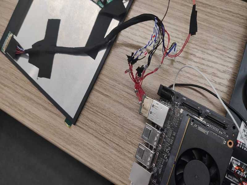
A display can look perfectly compatible on a specification sheet and still give you a black screen the moment it is connected. The panel may be the same size, use the same eDP interface, and even advertise the same resolution, yet one small assumption can derail the whole replacement or development project: treating 30-pin or 40-pin as a complete electrical specification. In practice, those numbers tell you how many contacts are available, not what every contact does or whether the source, cable, and panel were designed to work together.
A 30-pin and a 40-pin eDP connector are not automatically interchangeable. Pin count only describes the number of contacts. Real compatibility depends on connector series and pitch, lane count and mapping, AUX and optional HPD wiring, power and ground assignments, panel pinout, cable construction, source capability, target resolution and refresh rate, touch functions, and mechanical fit. These items must be verified as one system.
That difference becomes obvious during real troubleshooting. A team swaps an FHD panel for a higher-refresh model, orders a cable that is advertised as the correct 40-pin type, and expects the display to light immediately. Instead, the backlight turns on but the image never appears, or the screen works at 60 Hz and flickers at 144 Hz. The cable may not be defective at all; the source may have fewer active lanes, the pinout may differ, or the high-speed channel may simply have too little margin. The rest of this guide explains how to separate those problems before they become expensive revisions.

What Is the Difference Between 30-Pin and 40-Pin eDP Connectors?
A 30-pin and a 40-pin eDP connector mainly differ in the number of available electrical contacts, but pin count alone does not define bandwidth, resolution, touch support, or compatibility. Additional contacts in a 40-pin design may be used for more Main Link lanes, touch-related circuits, power, grounds, or other functions. Exact behavior depends on the connector family, pinout, source, panel, and cable design.
Pin Count vs Pinout
Pin count tells you how many contact positions a connector provides; pinout tells you what those positions actually do. That sounds basic, but it is the most important distinction in this topic. In an eDP assembly, contacts can carry Main Link differential pairs, the AUX channel, optional HPD, panel power, backlight control, grounds, shields, or implementation-specific functions. Two 40-position connectors can therefore look similar and still have different electrical assignments. For production documentation, every important contact should be defined by connector reference, pin number, signal name, from-to relationship, differential-pair membership, and power or ground function. The drawing should also state whether numbering is viewed from the mating face or cable side, because a mirrored reference can create a cable that is manufactured exactly to the drawing and still connects the wrong signals. Wire color is useful for assembly identification, but it should never be the only electrical definition.
Common 30-Pin and 40-Pin Patterns
There are recognizable market patterns, particularly in notebook replacement screens, but they should be treated as clues rather than standards. Many mainstream 30-pin panels are non-touch HD or FHD designs, and many 40-pin panels appear in touch, QHD, UHD, or high-refresh systems. The problem begins when those market tendencies are converted into hard rules such as ’30-pin always means two lanes’ or ’40-pin always means four lanes.’ Connector families such as I-PEX CABLINE include multiple position counts and different variants, while other families such as JAE FI-X use their own pitch and mechanical system. A useful sourcing description therefore goes beyond contact count and includes the exact panel part number, connector manufacturer and part number, contact pitch, mating orientation, cable part number when available, and required display mode. That extra detail usually saves more time than searching for another visually similar cable after the first sample fails.
| Item | 30-Pin eDP | 40-Pin eDP | What Actually Needs Verification |
| Contact positions | 30 | 40 | Physical connector family, pitch, mating direction, and exact part number |
| Common market use | Many standard non-touch HD/FHD panels | Often touch, QHD/UHD, or high-refresh panels | Exact panel model and system design |
| Lane count | Not defined by pin count | Not defined by pin count | Source and panel lane configuration |
| Touch support | Less common in typical notebook replacements | Common in some 40-position designs | Pinout and touch architecture |
| Resolution capability | Not fixed | Not fixed | Link rate, active lanes, timing, color depth, and compression |
| Interchangeability | Not automatic | Not automatic | Complete electrical and mechanical compatibility |
Performance Is a System Property
A 40-pin connector is not automatically faster than a 30-pin connector because performance belongs to the complete eDP channel, not the contact count. The source device must support the required link rate and lane count, the motherboard must actually route those lanes, the cable must preserve the differential geometry, and the panel receiver must support the target timing. The path is better understood as GPU or SoC to PCB routing, board connector, cable assembly, panel connector, and panel electronics. A change at any point can reduce margin. Cable construction matters as data rate rises: excessive pair separation, long stripped sections, poor shield termination, sharp bends, or an adapter with uncontrolled traces can all create impedance discontinuities. A continuity tester can confirm that every pin reaches the correct destination, but it cannot prove that the finished assembly will remain stable at the intended resolution and refresh rate. That is why eDP development normally combines mapping, electrical inspection, and system-level display validation.

Which Displays Use 30-Pin or 40-Pin eDP?
Thirty-pin eDP connectors are widely used in conventional non-touch notebook and embedded displays, including many HD and FHD panels. Forty-pin configurations are common in touch-enabled, higher-resolution, and higher-refresh displays. These are market patterns rather than fixed standards. Resolution, refresh rate, touch architecture, lane count, connector position, power requirements, and pinout still need to be checked against the exact panel and source design.
30-Pin Display Applications
A large number of mainstream laptop panels use 30-position eDP connectors, especially conventional 1366 x 768 and 1920 x 1080 non-touch displays. This is why replacement-screen catalogs often associate 30-pin eDP with standard FHD panels. The association is useful for initial filtering, but resolution alone cannot approve a replacement. Two 1920 x 1080 panels may use different connector positions, different pitch or receptacle families, different lane configurations, different voltages, and different refresh rates. Bandwidth also changes sharply with refresh rate even when resolution stays the same. A 1920 x 1080 image at 60 Hz and 24 bits per pixel represents about 3.0 Gbps of active pixel data before blanking and transport overhead; at 144 Hz, the active image data is about 7.2 Gbps. That is why two panels both described as ‘FHD eDP’ can place very different demands on the source, cable, and connector channel.
40-Pin Display Applications
Forty-position eDP connectors appear frequently in higher-performance notebook and embedded display systems because the additional contacts give designers more freedom to carry extra high-speed lanes, grounds, control functions, touch-related circuits, or power. Common examples include QHD and UHD panels, 120 Hz, 144 Hz, 165 Hz and higher-refresh gaming displays, touch-enabled laptop screens, and compact premium display modules. The bandwidth numbers show why these designs often need a more capable link. A 2560 x 1440 image at 60 Hz and 24 bits per pixel contains about 5.3 Gbps of active pixel data before overhead; at 165 Hz, it rises to about 14.6 Gbps. A 3840 x 2160 image at 60 Hz is about 11.9 Gbps before overhead. Those values do not directly tell you which connector is required, but they explain why lane count, link rate, and channel quality become increasingly important as display specifications climb.
Touch Changes the Picture
Touch-enabled systems are one of the main reasons ’40-pin eDP’ can be misleading. Some designs use the additional connector positions for touch-related USB or control circuits, power, and grounds, while another 40-position panel may use its available contacts in a high-bandwidth four-lane display implementation. Both products can appear in online listings under the same broad 40-pin label even though they are not electrically interchangeable. A better identification string includes the panel manufacturer and exact P/N, resolution, refresh rate, touch status, connector P/N, and original cable P/N where available. In product development, starting from the panel and board interfaces is more reliable than starting from contact count because the panel datasheet and board design can reveal lane mapping, power requirements, connector orientation, and control functions together. The practical lesson is simple: touch, resolution, refresh rate, and pin count are related design choices, but none of them is a substitute for the actual interface definition.

Are 30-Pin and 40-Pin eDP Connectors Interchangeable?
In most cases, 30-pin and 40-pin eDP connectors are not directly interchangeable. Different contact counts normally mean different physical connectors and may also mean different lane, power, touch, AUX, HPD, or ground assignments. An adapter only works when the source, panel, electrical mapping, bandwidth, power requirements, connector transitions, and signal integrity have been verified for that exact combination rather than assumed from appearance.
Physical Fit Is Only the First Check
A 30-position connector cannot directly mate with a 40-position receptacle, so the natural response is to look for an adapter cable. The mechanical transition is usually the easiest part. The harder problem is proving that the source and panel expect compatible electrical functions. A valid conversion needs to confirm source-side and panel-side connector part numbers, pin 1 orientation, active Main Link lanes, lane polarity, AUX mapping, optional HPD, panel power, backlight control, ground distribution, and any touch-related circuits. If the original system routes two Main Link lanes and the target panel requires four, a passive adapter cannot create the missing high-speed lanes. If the new panel assigns power or ground differently, simply moving wires to a larger connector can create a serious electrical fault. For that reason, a 30-to-40 or 40-to-30 conversion should begin with a source-to-sink pin and function map, not with a generic adapter drawing or an online product description.
The Motherboard Can Be the Limitation
Display upgrade projects often focus on the panel and cable while overlooking the source implementation. A motherboard connector may have enough physical positions for several display options, yet the board may route only a subset of the available eDP lanes on a particular product revision. Some contacts can be unpopulated, repurposed, or connected differently between configurations. Firmware and platform support can add another constraint. This becomes obvious when a 60 Hz FHD panel is replaced with a 165 Hz QHD panel: the new display requires substantially more transport capacity, and a new cable cannot compensate for source hardware that never provided the required link configuration. The compatibility chain is source capability, PCB routing, source connector, cable assembly, panel connector, and panel capability. Every stage has to support the target configuration. This matters especially in industrial equipment and long-life systems, where newer replacement panels may be mechanically similar but electrically different from the original generation.
Adapters Need Signal Integrity Too
At eDP data rates, an adapter cannot be treated as a simple set of copper traces that moves signals from one connector shape to another. Every added connector, PCB trace, flexible circuit, solder joint, or extended breakout section becomes part of the high-speed channel. These transitions can introduce impedance discontinuity, reflection, crosstalk, insertion loss, or shield and return-path problems. A converted assembly may pass continuity yet show black screens during boot, intermittent flicker, brief blanking, failure only at high refresh rate, or instability when the cable is bent into its installed position. This is why a one-time successful display image is not enough evidence for production approval. A stronger validation plan operates the target resolution and refresh rate, repeats power cycles, checks the normal mechanical routing, and reproduces expected use conditions. Where channel margin is critical, impedance or TDR measurements can complement system functional testing. The goal is to verify the finished path, not only the adapter itself.
How Do Lane Count and Pinout Affect eDP Compatibility?
Lane count determines how many high-speed Main Link channels carry display data, while pinout defines where those lanes and supporting functions appear on the connector. Widely deployed eDP systems can use 1, 2, or 4 Main Link lanes. A compatible cable must preserve lane mapping and polarity, AUX, optional HPD, panel power, grounds, shielding, and the electrical behavior of the complete high-speed path.
Lane Count and Bandwidth
Each eDP Main Link lane carries high-speed serial data, so total transport capacity depends on both the link rate and the number of active lanes. Common deployed DisplayPort and eDP link-rate levels include RBR at 1.62 Gbps per lane, HBR at 2.70 Gbps, HBR2 at 5.40 Gbps, and HBR3 at 8.10 Gbps. Under the 8b/10b encoding used by these link rates, the approximate payload per lane is 80 percent of the raw rate. This is useful for understanding why a panel upgrade may require additional lanes or a higher link rate, but it should not be used as a simple resolution calculator. Real display transport also depends on blanking intervals, bit depth, chroma format, timing, compression when used, and the actual capabilities of the source and sink. The engineering takeaway is that connector pin count and active lane count are separate variables, so a 40-position connector cannot be assumed to be a four-lane interface without documentation.
| Link Rate | Raw Rate / Lane | Approx. Payload / Lane | 2-Lane Payload | 4-Lane Payload |
| RBR | 1.62 Gbps | 1.296 Gbps | 2.592 Gbps | 5.184 Gbps |
| HBR | 2.70 Gbps | 2.160 Gbps | 4.320 Gbps | 8.640 Gbps |
| HBR2 | 5.40 Gbps | 4.320 Gbps | 8.640 Gbps | 17.280 Gbps |
| HBR3 | 8.10 Gbps | 6.480 Gbps | 12.960 Gbps | 25.920 Gbps |
Pinout Must Preserve Function
A correct eDP cable does more than connect the same pin number at both ends. The source and panel can use different connector families, so the design must preserve function rather than blindly preserve numbering. Main Link pairs need the correct lane identity and polarity, the AUX differential pair must be mapped correctly, panel power and grounds must reach the intended contacts, and optional HPD or backlight-related functions need to follow the actual platform design. Manufacturing drawings should clearly separate Main Link Lane 0 through Lane 3 where used, AUX, HPD, panel power, backlight functions, grounds, shield connections, and touch-related circuits where applicable. Every differential pair should remain identifiable from source connector to panel connector, and the drawing must state the view reference for each connector. This is especially important with fine-pitch connectors because a mirrored numbering reference can reverse the intended mapping while still looking orderly in a cable layout. Controlled pinout documentation is therefore one of the strongest safeguards against repeat production errors.
The Finished Assembly Matters
Signal integrity is determined by the finished assembly, not only by the raw cable. The complete channel includes the connector contact transition, exposed conductor near the termination, differential-pair spacing, shield termination, ground return, bend geometry, overall length, and any adapter or intermediate PCB. Around 100 ohms differential is a common architecture for eDP and similar high-speed display links, but the actual project target and tolerance should come from the system or cable specification rather than being assumed for every assembly. The area close to the connector is often the most vulnerable because tightly controlled micro-coax can lose its geometry over the final few millimeters if the conductors are stripped too far, spread apart, sharply bent, or terminated inconsistently. Open/short testing will not detect that type of degradation. Depending on project risk, validation can include TDR or impedance checks, target-resolution operation, high-refresh testing, repeated startup, bend-position testing, and system-level display stability before the production process is frozen.
How Do You Identify the Correct eDP Connector?
The most reliable way to identify an eDP connector is to combine the panel P/N, cable P/N, connector manufacturer and series, exact connector P/N, pin count, pitch, orientation, and pinout. When exact part numbers are unavailable, use clear photographs, dimensions, mating-side information, board and panel details, and the original cable or datasheet to narrow the candidates before approving a replacement or prototype.
Start With Part Numbers
The panel part number is usually the strongest starting point because one exact LCD or OLED model can reveal several critical details at once: interface type, native resolution, refresh rate, connector type and location, pin assignment, voltage, and mechanical outline. The original cable P/N is equally useful in replacement work because equipment manufacturers often use different harnesses for different panel options within the same chassis. If the connector manufacturer P/N is available, uncertainty drops further. Descriptions such as ’40-pin I-PEX’ or ’30-pin JAE’ are still too broad because fine-pitch connector families can include multiple orientations, locking styles, shells, contact counts, and mating parts. For recurring production, exact connector P/Ns should be placed in the controlled BOM rather than left as a descriptive label. That prevents a later purchasing or manufacturing substitution from replacing the approved connector with a visually similar component that mates differently or changes the electrical transition.
Identify From Photos Carefully
When part numbers are missing, photographs can start the identification process, but they should not be treated as proof. Useful images include a straight mating-face view, cable-side view, both side profiles, the locking structure, the complete connector beside a size reference, the board or panel receptacle, and any original cable label. Measurements such as overall connector width, contact pitch, mating height, cable exit direction, pin 1 location, shell geometry, and lock position help distinguish families that look nearly identical in a catalog image. Fine-pitch high-speed connector systems commonly appear around 0.4 mm or 0.5 mm pitch, while some LCD-oriented families use different pitches, including larger values. Pitch alone still does not identify a series. The mating component is often more useful than the cable-side connector by itself, because an exact board or panel receptacle P/N can lead directly to its approved mating plug. A disciplined identification process works from both sides and keeps unknowns visible until they are confirmed.
Check the Whole Interface
Before ordering or releasing an eDP cable, confirm the complete interface rather than stopping after the connector is identified. The review should cover the panel manufacturer and exact P/N, motherboard or controller model, source connector P/N, panel connector P/N, connector pitch, pin 1 reference, Main Link lane count and mapping, AUX polarity, optional HPD, panel power, grounds, resolution, refresh rate, cable length, routing and bend areas, touch requirement, and the agreed validation method. Most of this information can be collected from one panel datasheet, a board schematic or connector drawing, and a few good photographs. If an original cable exists, keep it as a reference until the new assembly has passed validation because continuity mapping, physical measurements, connector orientation, and installed routing can answer questions that a product photo cannot. The cost of collecting this information before sampling is usually much lower than debugging a black-screen or intermittent-link problem after materials and assembly time have already been committed.
- Confirm that the display interface is eDP rather than LVDS, MIPI, or another internal display interface.
- Record the exact panel P/N and the source board or system model.
- Identify both connector P/Ns, pitch, orientation, and pin 1 reference.
- Verify Main Link lane count, lane mapping, AUX, optional HPD, power, grounds, and touch-related functions.
- Define the target resolution and refresh rate rather than using panel size alone.
- Record overall cable length, critical bend zones, hinge routing, and connector exit direction.
- Agree on continuity, fit, display-function, and any high-speed validation required before production release.
How Do You Specify a Custom eDP Cable Assembly?
A custom eDP cable should be specified as a complete source-to-panel interconnect, not simply as a 30-pin or 40-pin cable. The specification should define connector P/Ns, panel and source information, pinout, lane configuration, cable length, target display mode, routing, shielding, mechanical constraints, and validation criteria. Those inputs can then be converted into a controlled drawing, prototype, test plan, and repeatable production revision.
Build a Complete RFQ
The most useful RFQ is not the longest one; it is the one that removes the highest-risk unknowns before material is ordered. For eDP development, those unknowns are usually connector identity, pinout, active lanes, source and panel capability, cable length, and mechanical routing. A customer with a complete board schematic and panel datasheet can start from a conventional build-to-print path. A project with only an old cable, panel P/N, photos, or a partial pin map can still begin, but the missing information has to be converted into controlled engineering data before volume production. SINO-CONN typically treats interface identification, lane and auxiliary-signal mapping, cable structure, drawing confirmation, prototype validation, and production control as one connected workflow. This keeps the RFQ practical without pretending that an incomplete photo is enough for final manufacturing approval. The goal is to move quickly at the beginning while making sure every high-risk assumption is resolved before the design is frozen.
| RFQ Item | Useful Input | What It Helps Confirm |
| Panel | Manufacturer + exact P/N | Sink-side interface, timing, connector, and mechanical requirements |
| Source board | Board model, schematic, or connector P/N | Available lanes, routing, power, and source capability |
| Connectors | Exact P/Ns or detailed photos + dimensions | Mating, pitch, orientation, locking, and sourcing |
| Pinout | Pin-to-pin table or existing cable mapping | Main Link, AUX, HPD, power, grounds, and auxiliary functions |
| Display mode | Resolution + refresh rate + touch status | Bandwidth and functional target |
| Cable geometry | Overall length, critical segments, routing photos or CAD | Signal margin, bend zones, and mechanical fit |
| Validation | Continuity, fit, display function, TDR/impedance if required | Release criteria for prototype and production |
Validate More Than Continuity
A professional eDP prototype should answer three questions at the same time: does it fit, is it wired correctly, and does it remain stable at the required display mode? Mechanical review checks mating, locking, connector exit direction, overall length, hinge routing, bend radius, connector strain, and enclosure interference. Electrical review begins with continuity, open/short, pin-to-pin mapping, power and ground verification, and differential-pair confirmation. High-speed validation can then add differential impedance or TDR where appropriate, target-resolution operation, target refresh rate, repeated power cycling, bend-position testing, and system functional testing. A cable that produces an image once should not automatically become the production reference. A marginal assembly can work at 60 Hz and fail at 144 Hz, or behave normally when flat on a bench and flicker when routed through the normal hinge position. Those are not rare mysteries; they are precisely the kinds of conditions that a good prototype and validation plan are designed to expose before scale-up.
Control the Approved Design
Once a prototype has been approved, the project shifts from finding a working solution to reproducing it consistently. The production package should control drawing revision, connector P/Ns, approved alternatives, pin assignments, cable or micro-coax construction, length tolerances, shielding method, termination geometry, labels, test requirements, and key inspection points. High-speed assemblies are especially sensitive to informal substitutions because a connector that fits can still have a different electrical transition, a similar-looking micro-coax can have different impedance or loss behavior, and a few extra millimeters of exposed conductor can reduce margin near the termination. None of those changes necessarily causes a continuity failure. For repeat orders, revision control is therefore as important as the first successful prototype. The objective is not merely to reproduce the appearance of the approved cable; it is to reproduce the electrical, mechanical, and manufacturing conditions that made the approved cable stable in the target system.
Final Takeaway
The useful answer to ’30-pin or 40-pin?’ is rarely found by counting contacts alone. A reliable eDP decision comes from connecting the physical connector to the complete electrical and mechanical system: source capability, active lanes, link rate, pinout, AUX and optional HPD, power and grounds, cable structure, shielding, panel requirements, routing, and validation. Thirty-pin is common in many standard non-touch displays, while 40-pin is common in many touch, high-resolution, and high-refresh designs, but those patterns should guide investigation rather than replace it. When a new or replacement cable is documented around exact part numbers and verified functions, the result becomes easier to prototype, easier to test, safer to approve, and far more repeatable in production. For a custom project, providing the panel P/N, board connector, existing cable or pin map, target display mode, and required length is usually enough to start a focused engineering review without turning the project into a guessing exercise.
Frequently Asked Questions
Is a 30-pin eDP connector compatible with a 40-pin eDP connector?
A 30-pin eDP connector is generally not directly compatible with a 40-pin eDP connector because the physical connector is different and the electrical implementation may also differ. Even if an adapter can bridge the mechanical connection, the source and panel still need compatible Main Link lanes, AUX, optional HPD, power, grounds, touch-related signals, and bandwidth. The correct decision is based on the source and panel pinouts plus connector and cable specifications, not only the number of contacts.
Is every 40-pin eDP connector a 4-lane connector?
No. Forty contact positions do not automatically mean four active eDP Main Link lanes. Many high-resolution and high-refresh panels use four-lane configurations, but other 40-position designs can allocate some contacts to touch, power, grounds, control, or other functions. Widely deployed eDP architectures may use 1, 2, or 4 Main Link lanes, so the active lane count should be confirmed from the panel datasheet, board schematic, approved cable drawing, or an existing validated assembly before a replacement is selected.
Can a 30-pin eDP cable support a 144 Hz display?
A 30-pin connector does not by itself answer whether 144 Hz is supported. The required bandwidth depends on resolution, color depth, timing, link rate, active lane count, and whether the source and panel support the same configuration. For perspective, 1920 x 1080 at 144 Hz and 24 bits per pixel contains about 7.2 Gbps of active pixel data before blanking and transport overhead. Some systems can support that requirement with an appropriate eDP implementation, while others cannot, so the exact platform must be checked.
How do I know whether my laptop screen uses 30-pin or 40-pin eDP?
Start with the exact panel model number and original display cable part number rather than counting contacts visually. The panel datasheet or a reliable part-number reference usually identifies the interface and connector. If those numbers are unavailable, inspect the connector with clear mating-face and side photographs, measure the pitch and overall width, note the connector location and cable exit direction, and identify the motherboard or panel mating receptacle. Do not rely on screen size or resolution alone because the same laptop family can use several different display configurations.
Can I replace a 30-pin screen with a 40-pin screen for a higher resolution?
Sometimes an upgrade is technically possible, but it should not be assumed from the panel dimensions. A higher-resolution 40-pin panel may require more active eDP lanes, a higher link rate, a different cable, different power assignments, different connector routing, or platform and firmware support that the original 30-pin system does not provide. The upgrade should be evaluated across the full path from source hardware and PCB routing to the cable and target panel. A passive adapter cannot add eDP lanes that were never routed on the motherboard.
What information is needed to develop a custom eDP cable assembly?
The most useful starting package includes the panel manufacturer and P/N, source board or controller information, connector P/Ns on both ends, pinout or existing cable mapping, required lane configuration, target resolution and refresh rate, cable length, routing or hinge constraints, touch status, and the required validation method. If some information is missing, an existing cable, interface photographs, board drawings, or panel datasheet can be used to begin identification, but the final production version should still be released against a controlled drawing, pin map, material definition, and test criteria.



