 Skip to content
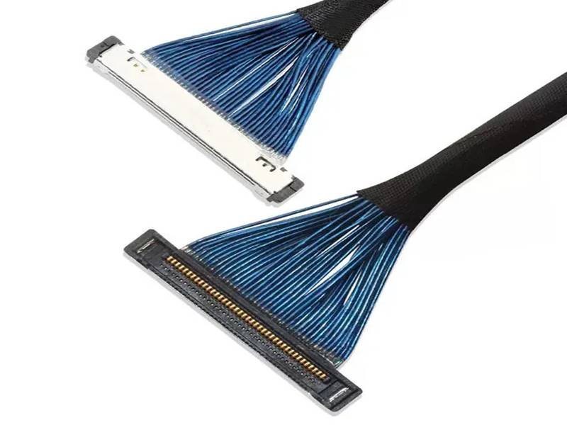
A few grams of cable rarely look important on a drawing, but they can matter once that cable is routed through a camera gimbal, robotic joint, medical imaging head, AR/VR device, UAV payload, or compact display hinge. In these systems, cable weight can influence inertia, drag, connector loading, routing force, available space, and even how smoothly a moving module behaves. That is why engineers searching for micro coax cable weight usually need more than a single catalog number.
Micro coax cable weight is normally specified as mass per unit length, commonly in grams per meter, and there is no universal weight for every micro coax construction. Actual mass depends on conductor size, cable OD, dielectric, shield, jacket, and length. For a finished cable assembly, connectors, ground bars, tape, heat shrink, reinforcement, discrete wires, and other components must also be included before total weight is known.
The practical question is therefore not simply, “How light is micro coax?” A better engineering question is, “How much weight can be removed while the assembly still meets its signal, mechanical, routing, and manufacturing requirements?” That distinction becomes especially important in high-density bundles, because tiny differences in one wire can become several grams after they are multiplied across 20, 30, or 40 channels. The sections below show how to calculate that effect and how to judge whether a lighter construction is actually the better one.

What Is Micro Coax Cable Weight?
Micro coax cable weight is the mass of a defined coaxial cable construction over a defined length, normally expressed in g/m, kg/km, or a similar unit. It is not the same as the finished assembly weight. A complete micro coax assembly can include connectors, ground bars, discrete wires, shielding, tape, heat shrink, reinforcement, and labels, so total mass must be calculated from the entire released design.
Cable Weight vs. Assembly Weight
Bare cable weight and finished assembly weight answer two different engineering questions. Bare cable weight describes the center conductor, dielectric, outer conductor or shield, and jacket before termination. Finished assembly weight describes what the customer will actually install in the device, including all terminations and protection materials. For a long cable, the cable itself may dominate the result, but for a short board-to-board, camera, or display connection, connector hardware can represent a surprisingly large share of the total mass.
This distinction is especially important when a device has a controlled weight budget. A gimbal designer may specify that the complete moving harness must stay below a certain number of grams, while a purchasing team may only have a cable datasheet showing g/m. Those numbers cannot be compared directly. The useful approach is to keep two controlled values in the engineering file: the mass per unit length of the selected wire and the measured or calculated mass of the finished assembly revision.
A finished micro coax assembly may include many items in addition to the cable itself, and each one can become significant when the whole harness weighs only a few grams. Connector hardware, grounding parts, shielding, protective materials, and identification features should therefore be included in the BOM-level weight calculation rather than treated as negligible accessories. Common contributors include the following components:
- Connector housings and contacts
- Ground bars or grounding hardware
- Discrete power and control wires
- Conductive tape or overall shielding
- Fabric or polymer wrapping
- Heat-shrink tubing and local reinforcement
- Pull tabs, labels, or identification materials
- Strain relief, overmold, or protective sleeves where required
How Weight Is Specified
For small electronic cables, grams per meter is usually the easiest unit to work with because assembly lengths are often measured in hundreds of millimeters. The basic relationship is straightforward: cable mass equals cable mass per meter multiplied by cable length in meters. A cable specified at 0.70 g/m would therefore contribute about 0.07 g at 100 mm, 0.175 g at 250 mm, 0.35 g at 500 mm, and 0.70 g at one meter, before any connector or assembly material is added.
Datasheets may also use kg/km or kg/100 m. One useful shortcut is that 1 kg/km is numerically equal to 1 g/m, so a published value of 3.2 kg/km also means 3.2 g/m. Engineers should still confirm whether the value is nominal, typical, or maximum, because weight can vary slightly with manufacturing tolerances. When finished mass is a controlled requirement rather than a rough design estimate, the approved prototype should be physically weighed and that result should be linked to the controlled drawing or BOM revision.
Why One Number Can Be Misleading
The term micro coax covers a wide range of constructions. An ultra-fine internal cable used between a camera module and processor board can have a very different diameter and mass from a miniature RF coax used between an antenna and radio module. Both may be called micro or miniature coax, yet their conductor size, dielectric geometry, shielding, jacket, impedance target, and mechanical purpose can be completely different. A weight figure without the underlying specification therefore has limited engineering value.
Length also changes what matters most. If a cable is 1.5 m long, reducing the cable mass by 0.5 g/m saves 0.75 g per channel. If the same connectorized link is only 50 mm long, that cable change saves just 0.025 g per channel, making connector weight or reinforcement a much larger percentage of the total. For meaningful comparisons, the project should identify the exact cable construction, AWG, OD, g/m, length, channel count, connector configuration, and whether the quoted number refers to cable-only or finished assembly mass.

Which Micro Coax Sizes Weigh Less?
Smaller-diameter micro coax cables generally weigh less because they contain less conductor, dielectric, shielding, and jacket material per meter. Higher AWG numbers usually indicate smaller conductors, but AWG alone cannot predict finished cable weight accurately. Two cables with the same AWG can have different outer diameters, shield constructions, dielectric thicknesses, jacket materials, and therefore different mass, flexibility, attenuation behavior, and mechanical performance in the finished assembly.
AWG and Conductor Mass
AWG is useful because it shows how quickly conductor cross-sectional area decreases as the gauge number rises. That reduction can support smaller OD and lower total cable mass, but the conductor is only one layer inside a coaxial structure. In very fine micro coax, the shield, dielectric, and jacket can contribute more mass than the center conductor itself. For that reason, theoretical copper weight is useful for understanding the trend, but it should never be treated as the finished cable weight.
The following table shows approximate copper-only mass for several nominal AWG sizes. The values are calculated from standard nominal conductor area and a copper density of about 8.96 g/cm3. They exclude plating, stranding effects, dielectric, shielding, jacket, and manufacturing tolerances, so they are best used as a comparison tool rather than a finished-product specification when evaluating real micro coax cable weight.
| AWG | Nominal conductor area | Approx. copper mass per meter | Relative copper mass vs. AWG 36 |
| 36 | 0.0127 mm2 | 0.114 g/m | 100% |
| 40 | 0.00501 mm2 | 0.045 g/m | 39% |
| 44 | 0.00198 mm2 | 0.0177 g/m | 16% |
| 46 | 0.00125 mm2 | 0.0112 g/m | 10% |
| 48 | 0.000793 mm2 | 0.0071 g/m | 6% |
| 50 | 0.000495 mm2 | 0.0044 g/m | 4% |
The table makes one point very clear: moving from AWG 36 to AWG 46 reduces nominal copper cross-section dramatically. It does not mean an AWG 46 finished coax weighs one tenth as much as an AWG 36 finished coax, because the surrounding layers do not shrink in exactly the same proportion. A lighter gauge can also change resistance, attenuation, current capability, connector termination range, and handling strength, so the gauge should be selected inside the complete electrical and mechanical design.
Cable OD Matters More Than AWG Alone
Overall diameter often gives a better first indication of complete cable mass than AWG because OD reflects the conductor plus the dielectric, shield, and jacket. A 0.25 mm and a 0.50 mm cable may appear only 0.25 mm apart in diameter, but for a circular cross-section the geometric area scales approximately with diameter squared. In pure geometric terms, a 0.50 mm circle has about four times the area of a 0.25 mm circle, although the actual mass ratio will differ because the internal materials are not uniform.
That difference becomes much more important in a bundle. If 30 or 40 coax channels are routed together, a small change in individual cable OD can alter bundle thickness, bend behavior, routing clearance, connector transition geometry, and overall mass. In micro coax development, OD should therefore be evaluated alongside channel count and the complete assembly envelope. A smaller cable is valuable only if it still terminates correctly, meets the signal requirement, and survives the intended routing and assembly process without forcing heavier protection elsewhere.
Same AWG, Different Weight
Two AWG 44 micro coax cables do not necessarily weigh the same because AWG mainly describes the center conductor. One cable may use a thinner dielectric and compact shield for a short protected internal connection, while another may use a thicker dielectric, stronger shield, or more robust jacket to meet different electrical or mechanical requirements. The center conductor may be nominally similar, but the rest of the cable can contain very different volumes of polymer and metal.
The practical comparison is therefore AWG plus OD plus g/m plus the relevant electrical and mechanical specifications. If two candidate cables both meet the project requirements but one is 0.3 g/m lighter, that difference may be trivial for a single short lead but meaningful in a large bundle. Across 30 channels at 400 mm each, a 0.3 g/m difference equals 3.6 g of cable mass. In a stationary cabinet that may not matter, but in a small UAV, wearable device, or moving camera module it can justify an engineering review.
What Determines Micro Coax Cable Weight?
Micro coax cable weight is created by every physical layer in the cable: center conductor, dielectric, outer conductor or shield, and jacket. Finished assemblies add connectors and protection materials on top of that. Metallic layers usually contribute more mass per unit volume than polymers, so conductor and shielding choices are important, while jacket thickness and reinforcement become increasingly influential in the final assembly.
Conductor, Dielectric, Shield, and Jacket
The center conductor is the most obvious material inside the cable, but it is only one part of the mass. The dielectric separates the conductor from the outer conductor and helps establish the cable’s electrical geometry. The shield provides the return path and electromagnetic containment, while the outer jacket protects the fine structure during processing, routing, and installation. Each layer contributes weight, but each layer also performs a function that cannot be removed casually simply to make the cable lighter.
A better approach is to right-size every layer for the application. A protected 120 mm internal camera link does not necessarily need the same mechanical construction as a cable that repeatedly moves through a robotic joint. Conversely, selecting an extremely delicate cable for a harsh assembly environment can force the design to add long heat-shrink sections, tape, or external sleeves, which may recover much of the weight that was saved by choosing the thinner cable. The lightest successful design is usually the one with the least unnecessary material, not the one with the smallest possible wire.
Shielding and Grounding
Shielding is one of the clearest weight-versus-performance trade-offs in micro coax design. More metallic shielding generally adds mass, yet reducing shielding without understanding the electrical return path can increase susceptibility to EMI, crosstalk, image noise, emissions, or high-speed communication errors. Individual micro coax channels already contain an outer conductor, but some assemblies add a second overall shield around the entire bundle to manage system-level noise or provide a more controlled grounding path.
The engineering question is not whether shielding can be removed, but which shielding layers are actually required. A useful review checks whether all channels need individual coax, whether the complete bundle needs an overall shield, where that shield is terminated, and whether noisy power or motor circuits run nearby. In some designs, localized shielding around a specific interference zone can reduce both mass and stiffness compared with full-length overall shielding. In other designs, removing the overall shield would be a false economy because the resulting EMI problem would outweigh the few grams saved.
Protection and Reinforcement
A surprising amount of finished cable assembly weight can come from materials that were added after the cable itself was selected. Polyester or fabric tape, conductive foil, braided sleeve, adhesive-lined heat shrink, reinforcement film, overmold, and strain-relief components can all be useful, but they should be tied to an actual mechanical or electrical need. Full-length protection that was added simply because it was convenient during assembly can make an otherwise lightweight micro coax bundle much heavier and stiffer than necessary.
Mechanical behavior matters as much as the number on the scale. A long, rigid heat-shrink section may protect a connector transition but move the bending stress to the exact point where the heat shrink ends. In gimbals, robotics, and wearable products, that can change how the bundle moves through the system. Protection is usually most efficient when it is localized at connector exits, sharp chassis edges, abrasion points, branch transitions, and defined strain-relief zones. This approach reduces unnecessary material while preserving the protection that actually prevents failure.
How Do You Calculate Micro Coax Cable Weight?
Calculate micro coax cable weight by multiplying the manufacturer’s mass-per-length value by the actual production cut length. For a multi-coax assembly, calculate every cable group separately, then add discrete wires, connectors, shielding, tape, heat shrink, reinforcement, and other BOM items. When finished weight is a controlled requirement, confirm the estimate by weighing the approved prototype and linking the result to the released revision.
Basic Cable Calculation
The basic formula is simple: cable weight in grams equals the specified grams per meter multiplied by cable length in meters. If the selected micro coax weighs 0.60 g/m and the production cut length is 280 mm, the cable contribution is 0.60 x 0.280 = 0.168 g per channel. If the same length is used for 20 channels, the total cable contribution becomes 3.36 g before connectors, shielding, and mechanical protection are added.
The important detail is the production cut length, not just the straight-line distance between the two connectors. A device drawing might show a 250 mm interface distance, while the manufacturing drawing requires 280 mm because the cable needs extra length for connector entry, routing, bend allowance, or a controlled flex path. If each of 40 channels is underestimated by only 30 mm, the design contains 1.2 extra cable-meters. At 0.60 g/m, that small dimensional difference adds 0.72 g to the assembly.
Multi-Channel Calculation
High-density assemblies should be divided into functional cable groups rather than calculated from connector pin count alone. Not every contact necessarily uses a coax channel. Some positions may be grounds, power conductors, discrete controls, or unused contacts. Different branches can also have different lengths, so a single “bundle length” may not represent the actual cable used. The following hypothetical example shows how a complete estimate can be built from individual groups and BOM items.
| Assembly element | Quantity | Length | Assumed unit mass | Calculated mass |
| Micro coax group A | 20 | 0.30 m | 0.60 g/m | 3.60 g |
| Micro coax group B | 10 | 0.22 m | 0.60 g/m | 1.32 g |
| Power wires | 4 | 0.28 m | 1.20 g/m | 1.34 g |
| Connector set | 2 | – | 0.45 g each | 0.90 g |
| Shield, tape, protection | – | – | BOM based | 0.65 g |
| Estimated total | – | – | – | 7.81 g |
The example shows why cable-only calculations are not enough. The micro coax groups contribute 4.92 g, yet the finished assembly reaches 7.81 g after power conductors, connectors, and protection are included. If the design target were 7.0 g, changing to a thinner coax would be only one possible response. The engineering team could also review connector choice, excess routing, power-wire sizing, protection length, or whether the full bundle needs the existing shielding arrangement.
Complete Assembly Weight
For an accurate finished estimate, the assembly can be treated as a simple BOM mass balance: all cable segments plus connectors plus termination components plus protection materials. For very lightweight assemblies, it is worth separating components that are normally ignored in heavier harnesses, such as pull tabs, labels, adhesive layers, small ground bars, and reinforcement strips. A few hundred milligrams can matter if the complete harness weighs only several grams.
The calculated result is still an estimate until the sample is built. A practical development record can compare calculated design mass, measured prototype mass, and the project-specific acceptance limit. Differences may come from adhesive, length tolerance, connector materials, small BOM items, or manufacturing variation. Once the prototype is approved, the measured value becomes a useful reference for later design revisions. If the connector part number, cable length, shielding, or protection changes, weight can be reviewed before the new revision is released to production.
Information Needed Before Quotation
A supplier cannot estimate finished mass accurately from a description such as “40-pin micro coax cable.” The project needs enough information to define the wire, connector, routing, and protection architecture. At minimum, the engineering team should know the active coax channel count, cable AWG or proposed construction, individual OD if controlled, nominal and cut lengths, connector part numbers, signal or impedance requirement where applicable, discrete power or control wires, shielding, branch structure, routing condition, and the maximum finished weight if one exists.
The most useful project inputs are those that explain both the electrical connection and the physical installation. Providing these details early reduces the risk of choosing a cable that looks light on paper but requires extra length, shielding, or reinforcement later. When available, the following information gives the engineering team a practical basis for calculating and validating finished assembly mass:
- Connector manufacturer and exact part number
- Number of active coax channels
- AWG, cable OD, or preferred cable family
- Nominal length and branch lengths
- Signal type, protocol, and impedance where applicable
- Power or control conductors in the same assembly
- Shielding and grounding requirement
- Tape, heat shrink, sleeving, or reinforcement requirement
- Routing envelope, bend path, and movement condition
- Finished assembly weight target and production quantity
When a complete cable drawing does not yet exist, a PCB layout, connector P/N, installation photo with dimensions, routing sketch, or existing sample can still provide enough context to begin engineering review. The important step is to convert those inputs into a controlled cable definition before mass production, so the weight estimate is tied to the same design that will actually be manufactured.

How Does Bundle Design Change Micro Coax Weight?
Bundle design can change total mass as much as the individual cable choice. Channel count, unequal lengths, routing allowance, service loops, discrete wires, connector count, overall shielding, wrapping, and reinforcement all accumulate. A very light single micro coax can therefore become a much heavier finished harness when 20 to 50 channels are combined, so weight should be evaluated at system level rather than wire level.
Channel Count Multiplies Small Differences
Small differences in mass per meter can become meaningful when they are repeated across many channels. Consider two candidate cable constructions, one at 0.80 g/m and another at 0.60 g/m. The difference is only 0.20 g/m. On one 300 mm channel, the saving is 0.06 g, which is easy to dismiss. Across 40 identical channels, however, the same change saves 2.4 g before any connector or protection changes are made.
The same multiplication applies to design waste. If a bundle contains 40 channels and every channel includes an unnecessary 50 mm service loop, the assembly carries two extra cable-meters. At 0.60 g/m, that loop adds 1.2 g. This is why high-density micro coax design should look at channel count and routing before automatically changing AWG. A cleaner layout can sometimes remove more mass than a more fragile cable, and it can also improve assembly consistency by reducing excess loops, uncontrolled bends, and movement inside the enclosure.
Routing Length Is Often Underestimated
Cable routes are rarely straight. A micro coax bundle may need to turn around a PCB, pass through a hinge, clear a motor or battery, follow a curved gimbal path, or enter a connector at a controlled angle. As a result, interface distance, engineering routing length, and production cut length are often three different numbers. Only the production cut length represents the actual material in the finished assembly, so weight calculations based on point-to-point distance can be optimistic.
Dynamic products make this more complicated. Too little cable length can pull directly on the connector at maximum movement, while too much cable creates loops, friction, extra mass, and uncontrolled motion. Gimbals and robotic joints should therefore be reviewed in more than one position, including the movement extremes. The goal is to provide enough free length for motion without carrying unnecessary material. When the route is optimized early, the project can often improve weight, bend behavior, connector loading, and serviceability at the same time.
Connector Count Changes the Balance
Connector mass stays relatively fixed while cable mass changes with length, so short assemblies can be dominated by connector hardware. If a connector set weighs 0.9 g and the cable portion weighs 6 g, the connectors represent about 13% of the complete 6.9 g assembly. If a shorter version uses only 1 g of cable, the same 0.9 g connector set represents about 47% of the 1.9 g total. In that case, changing wire gauge may deliver less savings than expected.
Branching can create the same effect because every additional connector end introduces housing mass, termination components, transition materials, and strain relief. A useful lightweight design review therefore separates total mass into categories such as cable, connectors, shielding, protection, and other components. The category with the largest share should receive attention first. If connectors dominate, a smaller wire may not solve the problem. If cable dominates, then AWG, OD, channel count, and routing become the highest-value areas to review.
How Can You Reduce Micro Coax Cable Weight?
Reduce micro coax assembly weight by optimizing the complete interconnect rather than automatically choosing the smallest AWG. The most effective changes can include a lighter validated cable, shorter routing, fewer unnecessary channels, smaller connectors, optimized shielding, and localized reinforcement. Every change should still meet electrical, signal, mechanical, termination, flex, and manufacturing requirements, because a lighter assembly is only useful if it remains reliable in the actual device.
Start With the Largest Weight Contributors
The fastest way to reduce mass is to identify where the mass actually comes from. A simple BOM-level review should separate cable, connectors, shielding, power conductors, protection, and other components before any redesign begins. This prevents engineers from spending time on a tiny conductor change when a heavy connector shell or long reinforced section is responsible for most of the assembly weight. The example below uses illustrative numbers to show how several small design changes can add up in a 30-channel, 300 mm assembly.
| Design change | Example calculation | Potential mass reduction |
| Change cable from 0.80 to 0.60 g/m | 0.20 x 0.30 m x 30 channels | 1.80 g |
| Shorten each channel by 40 mm | 0.60 x 0.04 m x 30 channels | 0.72 g |
| Reduce connector set by 0.25 g each | 0.25 x 2 connectors | 0.50 g |
| Remove 100 mm excess on 10 branches | 0.60 x 0.10 x 10 | 0.60 g |
The point is not that every project will achieve these exact savings. The point is that the design should attack the largest contributor first. If cable accounts for most of the mass, a lighter cable deserves review. If connectors account for nearly half, a connector or board-layout change may have more value. If protection is unusually heavy, localized reinforcement can provide savings without changing the signal-carrying cable at all. This keeps weight reduction connected to the real structure rather than turning it into a blind search for the thinnest wire.
Balance AWG, OD, and Electrical Performance
A smaller conductor can reduce mass, but it also changes resistance, current capability, attenuation behavior, termination sensitivity, and mechanical handling. The smallest available AWG is therefore not automatically the correct one. Cable selection should start with the system requirements: signal or protocol, impedance where applicable, cable length, current if any, connector termination range, routing envelope, bend or movement condition, and finished mass target. Only then should candidate cable constructions be compared for weight.
This is particularly important for high-speed and RF links. A cable that looks ideal on the scale may produce unacceptable loss, unstable impedance transitions, or termination difficulty at the chosen connector. In custom development, the best result is normally the smallest practical cable that still satisfies the signal and mechanical requirements with a repeatable manufacturing process. SINO-CONN commonly treats AWG, OD, shielding, connector orientation, routing, bend radius, and installation space as connected design variables rather than independent catalog choices, which is the right approach when weight is only one of several constraints.
Remove Redundant Structure First
One of the safest ways to reduce mass is to remove material that does not contribute meaningful function. Excess service loops, unused coax channels, full-length tape where local wrapping is enough, repeated heat-shrink layers, cosmetic heavy braid, oversized strain relief, and duplicate shielding are all worth reviewing. These changes can reduce weight without touching the electrical core of the cable, which often makes them lower-risk than moving immediately to a smaller conductor.
The key is to distinguish redundant material from necessary material. A shield required for EMI control is not redundant. A reinforcement zone that prevents conductor fatigue at the connector exit is not redundant. A 70 mm rigid heat-shrink section used simply because it is easy to assemble may be. Every reduction should be confirmed on the prototype because removing protection can expose the bundle to abrasion, handling damage, or stress concentration. The most successful lightweight assemblies are often simpler, shorter, and better routed rather than merely thinner.
Optimize for the Device, Not the Scale
The lowest measured mass is not always the best design. A drone cable that is 2 g lighter but requires a large unsupported loop can be worse in flight. A gimbal cable that is very light but too stiff can increase motor load. A camera cable that saves weight by reducing shielding may develop image noise, and a robotic cable with too little reinforcement may fail earlier at a repeated bend point. Weight has to be considered together with OD, bend radius, flexibility, dynamic drag, attenuation, EMI, connector retention, routing stability, and production repeatability.
This is particularly relevant in AI cameras, machine vision, medical imaging, robotics, UAVs, AR/VR devices, displays, and compact embedded electronics, where micro coax is often selected because several constraints exist at once. For a weight-controlled project, the strongest requirement is therefore not “use the lightest micro coax possible.” A much more useful specification is, “keep the finished assembly below the defined mass target while maintaining the approved connector, signal performance, routing envelope, bend behavior, and validation requirements.” That turns weight into a measurable engineering requirement instead of a vague purchasing preference.
Micro coax cable weight is easy to underestimate because the individual wire is so small, but the finished assembly is the number that matters in the device. AWG, cable OD, shielding, channel count, routing length, connectors, and protection all contribute, and their importance changes with the application. The most reliable approach is to calculate the architecture at BOM level, build a representative prototype, measure the finished mass, and then optimize the largest contributors without weakening signal or mechanical performance. For custom projects, SINO-CONN can review drawings, connector part numbers, routing information, channel count, and weight targets together so that the selected micro coax structure is practical to prototype, validate, and manufacture repeatedly.
Frequently Asked Questions
How much does micro coax cable weigh per meter?
There is no single standard weight per meter for all micro coax cables. Ultra-fine internal micro coax may weigh well below one gram per meter, while larger miniature RF coax can weigh several grams per meter or more. The exact value depends on conductor size, OD, dielectric, shield, jacket, and impedance construction. For engineering calculations, always use the published g/m or kg/km value for the exact cable part number being considered.
Does a higher AWG number always mean a lighter micro coax cable?
A higher AWG number generally means a smaller center conductor, so it often supports a lighter and smaller cable, but it does not guarantee a lower finished cable weight. The dielectric, shield, jacket, and overall diameter may differ substantially between two cable families. AWG should therefore be used together with OD and mass-per-length data, while the final selection must still meet resistance, attenuation, connector termination, mechanical, and signal requirements.
How do I calculate the weight of a multi-coax cable bundle?
Calculate the mass of each cable group by multiplying its g/m value by the actual cut length and the number of channels, then add all other components. Those additional items can include discrete power wires, connectors, ground bars, shielding, tape, heat shrink, labels, and reinforcement. If branches have different lengths, calculate them separately. For a weight-controlled design, the approved prototype should then be physically weighed to confirm the BOM-based estimate.
Is smaller cable diameter always better for lightweight designs?
Smaller OD usually reduces material volume and can lower both weight and bundle size, but the smallest cable is not always the best finished solution. Extremely fine constructions can be more sensitive to handling, termination, repeated bending, or signal loss and may require additional protection. The preferred cable is the smallest practical construction that meets electrical, signal, connector, routing, flex, and reliability requirements without adding enough reinforcement to cancel the original weight advantage.
How much can connector weight affect a short micro coax assembly?
Connector weight can become a major percentage of total mass when the cable length is short. A connector set that represents only a small part of a one-meter assembly can represent nearly half of a very short internal interconnect because connector mass remains fixed while cable mass falls with length. In compact camera, display, and embedded designs, connector selection, ground structure, and reinforcement can therefore offer more weight reduction than changing AWG alone.
What information should I provide for a micro coax weight estimate?
Provide the connector part numbers, active coax channel count, cable AWG or preferred construction, individual cable OD if controlled, nominal and cut lengths, branch dimensions, signal or protocol, impedance requirement where applicable, power or control wires, shielding, protection, routing conditions, movement requirements, and the finished weight target. A PCB layout, routing sketch, installation photo, or existing sample can also help when the final cable drawing has not yet been released.



