 Skip to content
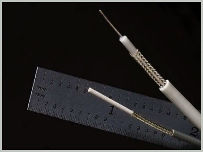
Micro coax cable size looks simple until a design has to fit inside a real product. An engineer may start with an AWG number, then discover that the finished cable outside diameter, connector pitch, channel count, impedance, bend path, and signal loss all affect whether the assembly will actually work. That is why a useful size decision goes beyond a basic AWG chart and treats the cable as part of a complete interconnect system.
For compact cameras, displays, medical imaging equipment, robotics, UAVs, AR/VR hardware, and other high-density electronics, a difference of only a few hundredths of a millimeter can change routing space and termination feasibility. At the same time, making the conductor smaller can reduce electrical and mechanical margin. This guide explains the practical relationships among AWG, cable O.D., impedance, signal performance, flexibility, connector compatibility, and production validation so that size choices can be made with fewer surprises.

What Are the Common Micro Coax Cable Sizes?
Common micro coax cables span a wide range of conductor sizes, with many published systems covering about 30-46 AWG and specialized ultra-fine assemblies extending to 48-50 AWG. AWG describes the center conductor rather than the finished cable diameter. Final cable O.D. also depends on dielectric thickness, shield construction, outer covering, and the impedance target of the specific coaxial design.
What Does Micro Coax AWG Mean?
AWG, or American Wire Gauge, is a conductor-size system in which a larger gauge number represents a smaller conductor. In micro coax, that number is useful because it gives a quick indication of conductor scale, but it does not fully define the cable. The finished coax also contains a dielectric layer, an outer conductor or shield, and an outer covering, so the complete diameter can be several times larger than the center conductor itself.
Conductor construction also matters. Many micro-coax specifications use stranded center conductors rather than a single solid wire because flexibility and termination behavior are important in compact assemblies. A generic solid-wire AWG conversion can therefore be useful for orientation, but it should not replace the actual cable drawing. The cable manufacturer’s specification remains the reliable source for center-conductor construction, finished O.D., impedance, shield design, and dimensional tolerances.
How Does AWG Compare with Cable OD?
The most common sizing mistake is treating AWG and cable O.D. as if they were interchangeable measurements. AWG mainly describes the center conductor, while O.D. describes how much physical space the complete coax occupies. O.D. is often the more important number for routing channels, connector termination limits, hinge clearances, molded guides, local reinforcement, overmold design, and the total cross-section of a multi-channel bundle.
The difference becomes obvious when looking at published reference constructions. An AWG 40 center conductor can be around 0.09 mm in diameter, while the finished micro coax may be around 0.33-0.37 mm depending on the impedance construction. If a mechanical designer uses the conductor diameter as the routing dimension, the cable may not fit even though the AWG selection appears correct on paper.
| AWG | Center Conductor Diameter | 45Ω Cable O.D. | 50Ω Cable O.D. |
| 30 | 0.300 mm | 1.04 mm | 1.16 mm |
| 32 | 0.240 mm | 0.82 mm | 0.90 mm |
| 34 | 0.190 mm | 0.67 mm | 0.73 mm |
| 36 | 0.150 mm | 0.49 mm | 0.55 mm |
| 38 | 0.120 mm | 0.39 mm | 0.46 mm |
| 40 | 0.090 mm | 0.33 mm | 0.37 mm |
| 42 | 0.075 mm | 0.29 mm | 0.33 mm |
| 44 | 0.060 mm | 0.24 mm | 0.26 mm |
| 46 | 0.048 mm | 0.22 mm | 0.24 mm |
Are 45Ω and 50Ω Cables the Same Size?
Not necessarily. Characteristic impedance is created by the relationship among the center conductor, dielectric geometry, dielectric constant, and outer conductor. The same center-conductor AWG can therefore appear in more than one finished O.D. when the cable is designed for different impedance targets. This is one reason a replacement cable should never be approved only because the AWG number matches the original cable.
For a high-speed or impedance-sensitive assembly, the meaningful comparison is not simply AWG 42 versus AWG 42. Engineers should compare the complete cable specification, including conductor construction, finished O.D., characteristic impedance, shield system, allowable termination method, and connector compatibility. A cable that looks equivalent by gauge alone can create a mechanical fit problem, change bundle geometry, or introduce an electrical mismatch at the connector transition.
What About 48 and 50 AWG?
AWG 48 and 50 sit at the ultra-fine end of micro-coax assembly design, where very small dimensional changes can matter. They can be valuable when a project has severe space, weight, or channel-density constraints, but engineers should not extrapolate their finished diameter from a larger-gauge chart. The exact cable drawing should be checked because ultra-fine constructions vary significantly by manufacturer, impedance, shielding method, and intended connector ecosystem.
SINO-CONN uses 46/48/50 AWG ultra-fine coax within micro-coax assembly development for compact, high-density applications, while treating AWG and cable O.D. as only part of the selection problem. Connector pitch, channel count, signal requirements, shielding, bend radius, and installation space must be reviewed together. At these dimensions, stripping, conductor handling, shield preparation, alignment, termination, and local strain control become increasingly sensitive manufacturing steps.
Which Micro Coax Cable Size Should You Choose?
The right micro coax size is the smallest construction that still satisfies signal performance, current, connector compatibility, mechanical durability, and manufacturing requirements with adequate margin. Choosing the highest AWG number simply to save space can create unnecessary insertion loss, fragile terminations, lower current capability, and production difficulty. Selection should begin with the application’s electrical and mechanical constraints rather than with gauge alone.
Which Is Better: 40, 42, 44 or 46 AWG?
There is no universal best gauge among AWG 40, 42, 44, and 46 because each size moves the design to a different point on the miniaturization-versus-margin curve. AWG 40 gives the largest conductor of the four and is often attractive when routing space is available. AWG 42 is commonly used where a modest reduction in diameter is valuable, while AWG 44 and 46 move farther toward compact routing and higher channel density.
Published reference data shows how quickly the finished diameter can change. In one 50-ohm micro-coax reference construction, the O.D. decreases from about 0.37 mm at AWG 40 to 0.33 mm at AWG 42, 0.26 mm at AWG 44, and 0.24 mm at AWG 46. Those fractions of a millimeter can become significant when many channels share a narrow passage, but the smaller gauge should still satisfy loss, current, connector, and reliability requirements.
Which Size Fits Tight Spaces?
For a tight mechanical envelope, the first dimensional check should normally use the finished cable O.D., not the AWG number. If an individual coax must remain below roughly 0.30 mm, for example, a particular AWG 42 construction at about 0.33 mm would already exceed that target, while some AWG 44 or 46 constructions may fit. The actual cable data sheet must still be used because O.D. varies with impedance and construction.
The critical area is often not the straight cable section. PCB exits, connector covers, hinge passages, molded channels, camera rotation zones, and transitions between structural parts can become the true limiting dimensions. An assembly that fits in a straight CAD view may interfere after the cable turns, fans out, or receives tape, shielding, or reinforcement. Mechanical evaluation should therefore include the complete installed path rather than a single nominal clearance.
Which Size Fits High-Density Designs?
High-density design is a system problem rather than a single-wire problem. When twenty, thirty, forty, or more micro-coax channels enter one fine-pitch connector, individual O.D. affects the whole fan-out region, local stiffness, packing density, and the amount of space required for shield termination. Reducing O.D. by only 0.05-0.10 mm per channel can materially change whether the bundle can pass through a narrow hinge or connector transition.
Connector pitch must be considered at the same time. A 0.35 mm, 0.40 mm, or 0.50 mm connector family may support different cable gauges, O.D. limits, pin counts, and termination geometries. If the board connector is selected after the cable size has already been frozen, the design team may discover that the preferred cable cannot be terminated by the chosen connector series. Cable and connector selection should therefore progress together.
Are 48 AWG and 50 AWG Right for Ultra-Fine Designs?
Ultra-fine gauges are appropriate when they solve a real packaging problem, not simply because a smaller number appears more advanced. They are most useful in miniature cameras, medical imaging assemblies, compact displays, AR/VR hardware, robotics, UAV gimbals, and embedded systems where larger micro coax physically prevents the required routing or channel density. If a larger cable fits comfortably and passes validation, unnecessary miniaturization can reduce manufacturing margin without improving the product.
As the conductor becomes finer, strip dimensions become less forgiving, accidental conductor damage is easier to create, shield handling becomes more delicate, and the termination zone becomes more sensitive to bending. Production controls should therefore include magnified inspection where appropriate, defined strip lengths, stable fixturing, connector-orientation control, channel mapping, shield-integrity checks, and clear strain-management rules. These process considerations can be as important as the nominal AWG number.

How Does Cable Size Affect Signal Performance?
Cable size affects signal performance through conductor resistance, attenuation, transmission-line geometry, shield construction, and connector transition quality. Finer conductors generally increase electrical loss over the same length, but AWG alone cannot predict high-speed behavior. Frequency, dielectric material, impedance, cable length, shield quality, connector design, PCB transitions, termination consistency, and the validation method all contribute to the final performance of the complete signal channel.
How Does AWG Affect Insertion Loss?
A smaller center conductor generally has higher resistance, and that contributes to greater conductor loss. At higher frequencies, dielectric loss, shield loss, surface-current effects, and connector transitions also become important. This is why insertion loss should always be considered against both frequency and length. A value stated without the test frequency, cable length, connector configuration, and reference plane provides very little engineering information for a high-speed design.
Length can magnify a size decision quickly. A very fine cable may have enough margin in a short 50-100 mm internal connection but consume too much of the available channel-loss budget when the same construction is extended to several hundred millimeters. The correct question is therefore not whether an AWG is generally suitable for high speed, but whether the complete cable-and-connector channel meets the loss limit of the actual protocol at the required length.
Does Smaller Cable Increase Signal Loss?
In general, a finer conductor tends to increase conductor loss when other variables remain similar, but real micro-coax families rarely hold every variable constant. A different gauge may use another dielectric thickness, shield design, conductor stranding, or outer covering, so two cables with the same AWG can still produce different insertion-loss curves. Engineers should rely on the manufacturer’s frequency-dependent data or project-specific measurement rather than a generic gauge rule.
This becomes especially important during prototype scaling. A short engineering sample may function normally even when the cable has relatively high attenuation because the total loss remains modest. The same structure can become marginal after cable length is increased, an additional connector is introduced, or PCB trace loss grows. High-speed size selection should therefore be made against the complete channel budget, not just against the cable’s visual thickness.
How Does Size Affect Impedance?
Characteristic impedance is not set by AWG alone. Coaxial impedance depends on the geometry of the center conductor, dielectric, and outer conductor as well as the dielectric constant of the insulating material. This is why the same center-conductor size can be used in more than one impedance construction and can produce different finished O.D. values. The cable drawing, not the gauge number, defines the intended transmission-line structure.
Termination quality can disturb impedance even when the raw cable is correctly designed. Excessive strip length, an uncontrolled shield opening, poor conductor positioning, or a weak ground transition can create a discontinuity near the connector. For LVDS, eDP, MIPI, camera, display, USB, or other high-speed interfaces, the actual impedance requirement should come from the system architecture and connector/cable specification, then be verified where the project requires it.
Do Smaller Cables Affect EMI and Crosstalk?
Micro coax has an important advantage in dense electronics because each signal conductor can be surrounded by its own shield, helping to control field interaction better than an unshielded single conductor. However, the benefit depends on shield continuity and grounding. A good cable can lose much of its EMI advantage if the shield is opened too far near the connector, damaged during processing, or connected inconsistently to the intended ground structure.
Higher channel density also increases the importance of the connector transition. Ground placement, shell connection, channel spacing, local shield termination, and pin assignment can affect crosstalk even though the cable body is coaxial. Moving from AWG 40 to AWG 44 does not automatically improve or worsen EMI. The smaller diameter changes packing geometry, while actual electromagnetic performance depends on the full cable, connector, shield, and grounding system.

How Does Size Affect Flexibility and Routing?
Smaller cable O.D. usually makes a micro coax easier to route through compact spaces and allows more channels within the same mechanical envelope, but it does not automatically provide longer dynamic flex life. Very fine conductors can be more sensitive to sharp bends and concentrated strain. Bend radius, exit direction, fixation points, bundle construction, motion pattern, and local reinforcement should therefore be reviewed together.
How Does Cable OD Affect Bend Radius?
Cable diameter influences how tightly a cable can be routed, but there is no reliable universal bend-radius multiplier that applies to every micro-coax construction. A smaller O.D. may allow a tighter geometric turn, yet the center conductor, dielectric, shield, and termination still experience strain. The allowable bend therefore depends on the cable design, whether the bend is static or dynamic, and how the cable is supported in the finished product.
A useful engineering review separates static bends, assembly bends, and repeated dynamic motion. A static cable may be formed once and remain nearly fixed, while a hinge or gimbal may reverse curvature thousands or millions of times during use. Those conditions should not share the same reliability assumption. For repeated movement, the representative bend radius, stroke, speed, fixation method, temperature, and motion path should be defined before a flex-life claim is made.
How Does Bundle Size Change with Channel Count?
Individual cable O.D. becomes increasingly important as channel count rises because cross-sectional area scales with the square of diameter. A forty-channel harness built from 0.37 mm cables consumes much more raw cable area than one built from 0.24 mm cables, even before tape, shields, drain wires, reinforcement, or an outer jacket are added. This is one reason ultra-fine cable can unlock mechanical designs that appear impossible with larger constructions.
The simple area comparison shown below is useful for relative planning but should not be treated as the final bundle O.D. Real bundles contain air gaps and packing inefficiency, and their shape may be flat, layered, oval, or locally reinforced rather than perfectly circular. The final harness envelope should be measured on the prototype in the actual routing state, especially near the connector fan-out and any narrow passage.
| Individual Cable O.D. | Example Reference Construction | 20 Cables: Sum of Bare Areas | 40 Cables: Sum of Bare Areas |
| 0.24 mm | AWG 46 50Ω / AWG 44 45Ω | 0.90 mm² | 1.81 mm² |
| 0.33 mm | AWG 42 50Ω / AWG 40 45Ω | 1.71 mm² | 3.42 mm² |
| 0.37 mm | AWG 40 50Ω | 2.15 mm² | 4.30 mm² |
| 0.46 mm | AWG 38 50Ω | 3.32 mm² | 6.65 mm² |
Which Sizes Work in Hinges and Moving Parts?
Hinge and gimbal applications require more than a thin cable. The terminated assembly must fit through the available opening, reach the correct connector orientation, and move without repeatedly pulling or bending the termination zone. A compact AWG 42 or AWG 44 structure may help the geometry, but the actual cable family still needs to be suitable for the intended movement and should be validated in the representative motion path.
A common design error is checking the cable only in a neutral position. In a gimbal or hinge, curvature can change substantially across the full range of motion, and a cable that looks relaxed at center position may become sharply bent or stretched at an endpoint. CAD review should therefore include multiple motion positions, and physical samples should be cycled through the real routing path whenever movement is a meaningful reliability requirement.
How Do You Avoid Stress at the Connector?
The most vulnerable area is often the transition from the flexible cable body to the terminated connector region. Stripping and shield preparation change the local structure, and a sharp bend immediately behind the connector can concentrate stress where the assembly has the least mechanical tolerance. Repeated movement at that location can lead to conductor fatigue, shield damage, intermittent contact, or gradual loss of retention even when the middle of the cable remains healthy.
A better layout allows the cable to leave the connector in its intended direction before the major bend begins. Local tape, heat-shrink, covers, adhesive, or other reinforcement can help when appropriately designed, but reinforcement should not create an abrupt stiffness boundary that simply moves the failure point a few millimeters away. The review should include connector exit, nearby edges, fixation points, maximum motion position, and the assembly process used to place the cable.
Which Micro Coax Sizes Fit Your Connector?
Micro coax size must fall within the approved cable range of the exact connector series. Connector brand alone is not enough because different series from the same manufacturer can support different AWG sizes, cable O.D. limits, pitches, pin counts, and termination methods. The cable and connector should therefore be selected and validated as one termination system rather than as two independent components.
Which AWG Sizes Fit I-PEX Connectors?
I-PEX provides a useful example of how connector compatibility changes by series. CABLINE-UY uses a 0.35 mm pitch and is published for AWG 40 and 42 micro coax, while CABLINE-CBL uses a 0.40 mm pitch and supports AWG 40 through 46. CABLINE-VS uses a 0.50 mm pitch and covers a different gauge range. These published ranges show why a brand-level statement is not enough for engineering release.
Current capability can also change with the wire size and connector configuration. Published CABLINE-VS reference ratings, for example, show lower per-contact current for finer supported gauges under the manufacturer’s stated conditions. Those numbers belong to that specific connector system and should not be reused as general micro-coax ampacity values. The exact connector datasheet should be used for current, voltage, cable O.D., contact count, and derating conditions.
| Connector Series | Contact Pitch | Published Micro-Coax Sizes | Signal Pin Counts |
| CABLINE-UY | 0.35 mm | AWG 40, 42 | 5, 10, 12 |
| CABLINE-CBL | 0.40 mm | AWG 40, 42, 44, 46 | 30, 40 |
| CABLINE-CA II | 0.40 mm | AWG 36*, 38, 40, 42, 44* | 20, 30, 40, 50 |
| CABLINE-VS | 0.50 mm | AWG 36, 38, 40, 42, 44 | 20, 30, 40, 50 |
Which Sizes Fit Hirose and JAE Connectors?
The same rule applies to Hirose, JAE, KEL, and other fine-pitch connector ecosystems. Each manufacturer offers multiple families with different pitches, mating heights, signal counts, cable ranges, locking features, and termination methods. Saying that a cable is compatible with a brand does not define enough information for production. The exact series and part number should be identified whenever possible before the cable gauge and O.D. are frozen.
When the exact part number is not available, the engineering review should establish at least the connector family, pitch, pin count, mating interface, board-side part, orientation, and cable exit direction. SINO-CONN supports micro-coax development around I-PEX, HRS/Hirose, JAE, KEL, and customer-specified miniature connector systems, but final compatibility is confirmed against the actual connector and cable specification rather than assumed from the brand name.
How Does Connector Pitch Limit Cable Size?
Connector pitch is the center-to-center spacing between adjacent contacts, but it is not the same as allowable cable O.D. A 0.35 mm-pitch connector does not automatically accept every cable with a 0.35 mm outside diameter. The termination must also accommodate the center conductor, dielectric, shield, ground structure, cable spacing, connector cover, and manufacturing tolerances, so the approved cable range must come from the connector documentation.
Fine pitch does, however, tighten the available mechanical envelope. As pitch decreases and channel count increases, the fan-out area becomes more sensitive to individual cable diameter, shield geometry, and cable organization. A design using a 0.35 mm or 0.40 mm connector may therefore require smaller micro coax than a 0.50 mm system, but the actual choice is still series-specific rather than a universal pitch-to-AWG conversion rule.
Is Smaller AWG Always Compatible?
No. A thinner cable is not automatically easier to terminate. Contacts, solder lands, shield clamps, covers, and termination tooling are designed around a defined range of conductor and cable dimensions. If the cable is too small, conductor positioning, shield retention, or mechanical support may become unreliable. If it is too large, neighboring channels can interfere, the cover may not close correctly, or the cable may exceed the allowed exit geometry.
For a new combination, sample termination is often the fastest way to expose problems that an AWG comparison cannot reveal. The prototype can show whether strip lengths are stable, the conductor sits correctly, the shield can be handled without damage, the connector closes and retains properly, and the completed assembly routes without excessive local stress. Exact cable part numbers should then be controlled in the drawing or BOM to prevent unintended substitutions.
How Do You Specify Micro Coax Cable Size?
A useful micro coax specification defines more than AWG. It should identify cable O.D., impedance, signal requirements, length, connector part numbers, channel count, pinout, shielding, routing space, bend conditions, and applicable electrical or mechanical tests. These inputs allow the cable size to be selected against the real system and give manufacturing teams a controlled definition that can be repeated after prototype approval.
What Specs Should You Provide?
Start with the electrical function. State what the cable carries, such as a camera link, display interface, RF path, clock, high-speed protocol, control signal, or power. Where relevant, include lane rate or operating frequency, characteristic impedance, voltage, current, grounding requirements, and the acceptable loss or functional criteria. A supplier can make a much better size recommendation when the signal requirement is known instead of receiving only an AWG target.
Next define the mechanical envelope. Useful information includes maximum individual cable O.D., available bundle width and thickness, overall length, branch lengths, connector orientation, cable exit direction, bend path, hinge geometry, PCB keep-out area, fixation points, and any weight target. Connector information should be as exact as possible. A manufacturer part number is ideal; otherwise clear images, pin count, pitch, mating interface, and dimensional references can help identify the correct system.
How Do You Balance Size and Performance?
Separate hard constraints from preferences before choosing the gauge. If the mechanism absolutely requires an individual cable below 0.30 mm O.D., that becomes a firm mechanical boundary. The engineering task is then to find constructions that satisfy that limit while still meeting signal loss, impedance, current, connector, and reliability requirements. If more space is available, a slightly larger cable may provide better margin with no practical downside.
Cable length can shift the decision. An ultra-fine cable may work comfortably across a short internal connection but consume too much signal margin across a longer route. Current is another boundary, particularly when some coax channels also carry DC power or bias. The final size should therefore balance mechanical packaging, electrical performance, connector capability, manufacturability, availability, and cost rather than optimizing one dimension in isolation.
What Should Be Validated Before Production?
Mechanical validation should confirm individual cable O.D., finished bundle dimensions, overall length, connector orientation, routing clearance, and installed bend conditions. If the assembly moves during operation, the review should include the relevant motion positions and, where needed, representative cycling. These checks are especially important for micro coax because a small dimensional change near the connector or bundle transition can create an installation conflict that is not visible from the raw cable specification.
Electrical verification normally begins with channel mapping and continuity/open/short checks, with insulation testing added where appropriate. High-speed or RF projects may require impedance or TDR measurement, insertion loss, return loss, functional signal testing, or system-level validation. Shield integrity should also be verified as part of the completed assembly because a well-designed raw cable can still perform poorly if shield termination or grounding is inconsistent during assembly.
How Do You Confirm the Final Cable Size?
The final size should be frozen only after the cable, connector, routing geometry, and electrical requirements have been evaluated together. The released drawing should identify the selected cable specification, connector part numbers, pinout, length, tolerances, orientation, and critical dimensions. The BOM should control the exact cable identity rather than stating only a generic phrase such as AWG 42 micro coax, because another AWG 42 construction can differ in O.D., impedance, shielding, and performance.
The prototype then becomes the physical confirmation of that engineering definition. It should be checked for connector mating, PCB fit, routing, channel mapping, electrical function, and project-specific signal or mechanical requirements. SINO-CONN can start micro-coax development from a connector part number, PCB layout, installation-space information, drawing, or existing sample, but the project should move into production only after those inputs have been converted into an approved, testable cable definition.
Conclusion
Micro coax cable size is best treated as an engineering decision rather than a single catalog number. AWG tells you the scale of the center conductor, while finished O.D. tells you how the cable occupies real space. Impedance, insertion loss, current, shielding, connector pitch, channel count, bend path, and termination method then determine whether that size can actually support the application. Looking at those variables together prevents many of the common problems that appear after the mechanical design has already been frozen.
For a new assembly, the most dependable path is to define the electrical requirement and mechanical envelope first, narrow the cable and connector options, build a representative prototype, and validate the dimensions and performance before release. That process is especially important at 44, 46, 48, and 50 AWG, where small changes in construction can materially affect handling and fit. A controlled drawing, exact cable specification, connector part number, and validated sample provide a far stronger production baseline than an AWG number alone.
Frequently Asked Questions
What is the smallest micro coax cable size?
There is no single smallest size that applies to every micro-coax family. Commercial and custom assemblies can extend into the 48-50 AWG range, but the finished O.D. depends on conductor construction, dielectric, shielding, impedance, and the connector system. The practical lower limit is therefore set by the cable and connector ecosystem that can be manufactured and validated for the application’s signal, mechanical, and reliability requirements.
What is the difference between AWG and cable OD?
AWG describes the size of the center conductor, while cable O.D. measures the outside diameter of the complete coaxial cable. The finished cable includes the conductor, dielectric, shield, and outer covering, so its O.D. is much larger than the conductor diameter. Mechanical designers usually need the O.D. for routing and packaging, while electrical and manufacturing teams need both AWG and the full cable construction.
Is 50 AWG micro coax better than 40 AWG?
Not automatically. AWG 50 can provide important space and weight savings in highly compact products, but AWG 40 generally offers a larger conductor and more electrical and mechanical margin. The better choice depends on routing space, cable length, signal-loss budget, current, connector compatibility, movement, and manufacturability. If AWG 40 fits and meets the product requirements, changing to AWG 50 may add complexity without delivering a useful system benefit.
How do I choose between 40, 42, 44 and 46 AWG micro coax?
Start with the maximum finished O.D. and connector series, then check signal performance, cable length, current, and bend requirements. AWG 40 provides the largest conductor of these four, while AWG 42, 44, and 46 progressively reduce size. The final decision should use the exact cable datasheet because O.D. and electrical performance vary by construction, even when two products share the same AWG number.
Does smaller micro coax have more signal loss?
A finer center conductor generally contributes to higher conductor loss when other variables are similar, but AWG alone does not determine the final insertion loss. Frequency, cable length, dielectric material, shield construction, connector transition, and PCB losses also matter. For high-speed links, compare the manufacturer’s frequency-dependent cable data or test the representative assembly against the actual channel-loss requirement rather than relying on a generic gauge comparison.
Can the same AWG micro coax have different outer diameters?
Yes. Two micro-coax cables with the same center-conductor AWG can have different finished O.D. values because dielectric thickness, impedance target, shield construction, conductor stranding, and outer covering can differ. This is common enough that a drawing or BOM should control the exact cable part number or full cable specification. Approving a substitute only because the AWG matches can create connector, routing, and signal-performance problems.
What information is needed to quote a custom micro coax cable assembly?
The most useful starting information includes connector manufacturer and part numbers, pinout, channel count, cable length, target AWG or maximum O.D., signal or protocol, impedance where applicable, current and voltage requirements, routing space, bend or movement conditions, shielding and grounding expectations, and estimated quantity. A drawing is helpful but not always required at the first step; a sample, PCB interface, or clear mechanical information can also support engineering review.



