 Skip to content
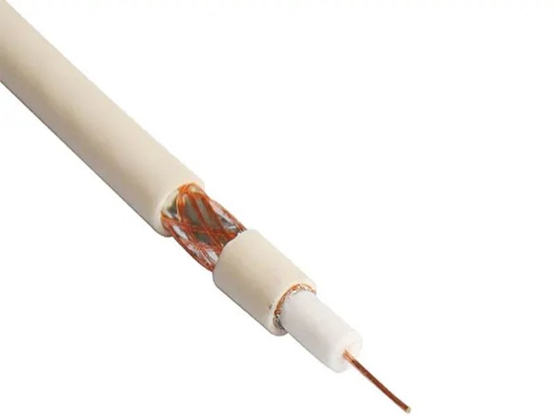
When signal problems show up in real systems—unstable data, unexpected noise, reduced transmission range—most people first suspect chips, antennas, or software. But in many cases, the real issue is much simpler and more hidden: poor cable shielding. At high frequencies, signals are no longer just electrical currents—they behave like electromagnetic waves that can leak out, pick up noise, or interfere with nearby systems.
Coaxial cable shielding works by surrounding the signal path with conductive layers that block external electromagnetic interference (EMI) and prevent signal leakage. These shielding layers—typically foil, braided metal, or multiple combined layers—create a controlled environment where signals remain stable, protected, and efficient even in high-frequency or noisy conditions.
In real projects, many customers come to Sino-Conn after experiencing signal instability without knowing why. One OEM client once replaced a single-layer shielded cable with a double-shielded design and saw interference issues disappear immediately—without changing any electronics. That’s when shielding stops being a “detail” and becomes the difference between failure and performance. Let’s break it down.
What Is Coaxial Cable Shielding?
Coaxial cable shielding is the conductive layer (or layers) wrapped around the signal core of a coaxial cable, designed to protect the signal from external interference and prevent internal signal leakage. In practical terms, shielding is what keeps your signal “clean” as it travels through the cable—especially in environments filled with electrical noise, multiple devices, or high-frequency transmission.
For many buyers, shielding is often treated as a basic feature. But in real projects, it directly affects whether a system works reliably or not. A cable with insufficient shielding may look identical on the outside but can cause unstable signals, data errors, or reduced performance once installed.
What Is Coaxial Cable Shielding Made Of?
Coaxial cable shielding is typically made from conductive metals such as aluminum or copper, applied in different structures depending on performance requirements.
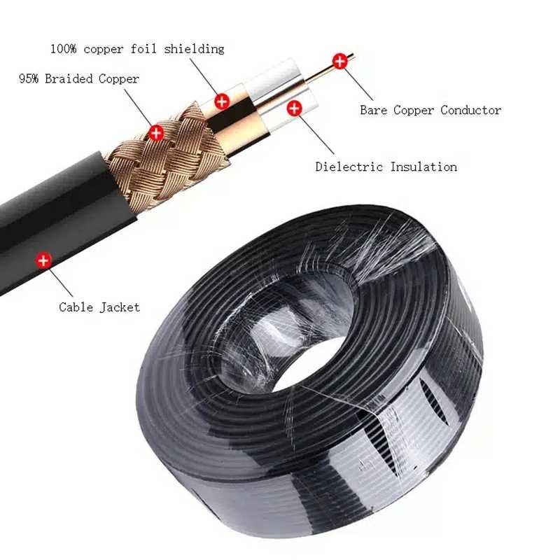
The most common shielding materials and structures include:
- Aluminum foil (often bonded with polyester film)
- Copper braid (bare copper or tinned copper)
- Combined foil + braid structures
- Multi-layer shielding (double or triple layers)
Each material serves a different purpose:
| Shield Type | Material | Key Advantage | Limitation |
|---|---|---|---|
| Foil | Aluminum | 100% coverage, strong EMI blocking | Lower flexibility |
| Braid | Copper | Flexible, durable | Small gaps in coverage |
| Foil + braid | Combined | Balanced performance | Slightly higher cost |
| Multi-layer | Multiple materials | Maximum protection | Higher complexity |
From a real-use perspective:
- Foil is good at blocking high-frequency interference
- Braid provides mechanical strength and flexibility
- Combining both gives more reliable performance in most applications
At Sino-Conn, shielding material is selected based on how the cable will actually be used. For example, cables used in outdoor telecom systems may require corrosion-resistant materials, while industrial cables may need stronger mechanical protection.
Why Is Coaxial Cable Shielding Important?
Shielding is critical because RF signals are highly sensitive to their environment. Without proper shielding, signals can be affected by external noise or even interfere with nearby systems.
Here are the main problems shielding solves:
- Blocks electromagnetic interference (EMI) from external sources
- Prevents signal leakage from the cable
- Maintains consistent signal transmission
- Reduces noise and improves system reliability
To understand the impact, consider this comparison:
| Condition | Poor Shielding | Proper Shielding |
|---|---|---|
| Signal clarity | Unstable | Stable |
| Noise level | High | Low |
| Data accuracy | Reduced | Reliable |
| System performance | Inconsistent | Consistent |
In real projects:
- Industrial environments often have motors and power systems generating EMI
- Telecom systems operate in crowded signal environments
- Medical devices require low-noise conditions
One common situation is that a system works fine during testing but fails in real deployment. In many cases, this is due to insufficient shielding that cannot handle real-world interference.
Sino-Conn often helps customers upgrade shielding design after identifying these issues during evaluation.
What Is Single vs Double Coaxial Cable Shielding?
The difference between single and multi-layer shielding is mainly about how much protection the cable provides.
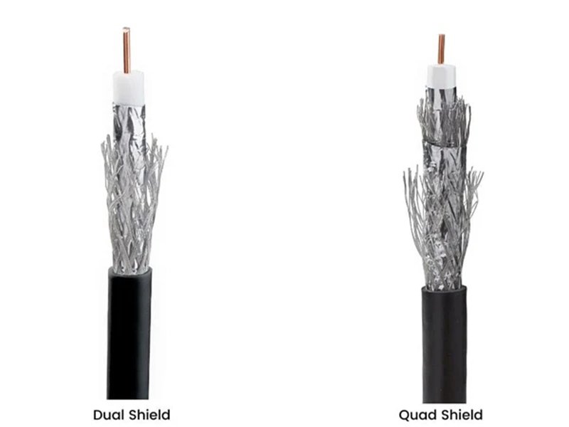
Single shielding uses one conductive layer, either foil or braid. It is suitable for basic applications where interference levels are low.
Double shielding combines two layers—typically foil + braid—to improve protection and stability.
Here is a practical comparison:
| Type | Structure | EMI Protection | Flexibility | Cost |
|---|---|---|---|---|
| Single shield | Foil or braid | Moderate | High | Lower |
| Double shield | Foil + braid | High | Medium | Moderate |
| Triple shield | Multi-layer | Very high | Lower | Higher |
In real-world use:
- Single shielding is often used in low-frequency or low-noise environments
- Double shielding is the most common choice for general RF applications
- Triple shielding is used in high-precision or high-interference systems
From customer experience:
- OEM factories often start with single shielding to reduce cost
- Engineers usually recommend double shielding for reliability
- High-end applications may require triple shielding
Sino-Conn provides all these options and helps customers choose based on actual operating conditions, not just initial cost.
How Does Coaxial Cable Shielding Work?
Coaxial cable shielding works by creating a conductive barrier around the signal path that both blocks external electromagnetic interference (EMI) and keeps the internal signal from leaking out. In real applications, this means your signal stays stable even when the cable runs next to motors, power lines, or other RF systems.
How Does Coaxial Cable Shielding Block EMI?
Every electrical device generates electromagnetic fields. When these fields reach a cable, they can induce unwanted signals (noise) into the conductor. Shielding acts as the first line of defense.

The shielding layer blocks EMI in two main ways:
- Reflection: The conductive surface reflects incoming interference away
- Absorption: Part of the interference is absorbed and dissipated
Here is what happens in practice:
| Environment | Without Shielding | With Shielding |
|---|---|---|
| Industrial (motors, drives) | Frequent signal noise | Stable signal |
| Office electronics | Minor interference | Clean signal |
| RF systems | Cross interference | Controlled performance |
From real customer feedback:
- Systems located near power equipment often experience noise spikes
- After switching to better-shielded cables, these issues are reduced or eliminated
For example, in an industrial automation project, replacing a low-coverage braided cable with a foil + braid design reduced interference-related signal errors significantly.
Sino-Conn typically asks about the installation environment early in the project, because shielding requirements depend heavily on where the cable will be used.
How Does Coaxial Cable Shielding Stop Signal Leakage?
At high frequencies, signals behave like electromagnetic waves. Without proper containment, part of the signal energy can escape from the cable.
Signal leakage leads to:
- Reduced signal strength at the destination
- Potential interference with nearby devices
- Lower overall system efficiency
Shielding acts like a closed channel that keeps the signal inside.
Here is a simplified comparison:
| Condition | Signal Behavior | Result |
|---|---|---|
| No shielding | Signal radiates outward | High loss |
| Partial shielding | Some leakage | Moderate loss |
| Full shielding | Signal contained | Efficient transmission |
Leakage becomes more critical as frequency increases:
| Frequency | Leakage Risk | Shielding Importance |
|---|---|---|
| <500 MHz | Low | Moderate |
| 1–3 GHz | Medium | High |
| >3 GHz | High | Critical |
In real use:
- Communication systems may lose range due to leakage
- High-frequency applications may fail performance tests
One Sino-Conn customer working on RF modules found that improving shielding reduced signal loss enough to avoid adding amplifiers, saving both cost and complexity.
How Does Coaxial Cable Shielding Improve Signal Stability?
Signal stability is about consistency over time and across environments. A stable signal does not fluctuate due to external conditions.

Shielding improves stability by:
- Reducing random noise fluctuations
- Preventing interference from nearby cables
- Maintaining consistent transmission conditions
In systems where multiple cables are routed together, poor shielding can cause cross-talk, where signals from one cable affect another.
Here is a real comparison:
| Condition | Poor Shielding | Good Shielding |
|---|---|---|
| Signal fluctuation | Frequent | Minimal |
| Noise spikes | Common | Rare |
| System reliability | Low | High |
From practical experience:
- Engineers often notice measurement variations when shielding is insufficient
- OEM factories report fewer field issues after upgrading shielding
Sino-Conn designs shielding structures based on real usage conditions, helping customers achieve stable long-term performance rather than just passing initial tests.
How Do Different Shielding Layers Work Together?
Most real-world RF cables do not rely on a single shielding layer. Instead, they combine multiple layers to improve performance.
Typical combinations include:
- Foil + braid
- Braid + foil + braid
- Multiple foil layers
Each layer serves a different role:
| Layer | Function |
|---|---|
| Foil | Provides full coverage, blocks high-frequency EMI |
| Braid | Adds mechanical strength and grounding |
| Additional layers | Improve overall shielding effectiveness |
Why combine layers?
- Foil alone provides coverage but lacks durability
- Braid alone provides flexibility but has small gaps
- Combining both balances performance and usability
Performance comparison:
| Structure | EMI Protection | Flexibility | Typical Use |
|---|---|---|---|
| Foil only | High | Low | Static installations |
| Braid only | Moderate | High | მოძრავი systems |
| Foil + braid | Very high | Medium | Most RF applications |
| Multi-layer | Maximum | Lower | High-precision systems |
In practice:
- Double shielding is the most common choice
- Multi-layer shielding is used in high-noise environments
Sino-Conn helps customers choose the right structure based on actual needs, avoiding both under-design and unnecessary cost.
How Does Shielding Connect to Ground?
Shielding only works effectively when it is properly grounded. Without grounding, the shielding layer cannot fully dissipate interference.
Grounding provides a path for unwanted signals to flow away from the cable instead of affecting the signal conductor.
Key points:
- Shield must be electrically connected to ground
- Connectors must maintain shielding continuity
- Poor grounding reduces shielding effectiveness
Common issues:
| Problem | Result |
|---|---|
| Incomplete grounding | Reduced EMI protection |
| Poor connector contact | Signal instability |
| Broken shield continuity | Increased noise |
In real applications:
- Connector quality plays a major role in maintaining shielding continuity
- Poor assembly can break the shielding path
Sino-Conn ensures proper grounding through:
- Precision connector assembly
- Continuous shielding design
- Full inspection during production
This ensures that shielding works as intended in real conditions, not just in theory.
Which Coaxial Cable Shielding Types Are Used?
Coaxial cable shielding types mainly include foil shielding, braided shielding, and multi-layer combinations such as double or triple shielding. Each type has its own strengths in terms of EMI protection, flexibility, durability, and cost. In real projects, the right choice depends less on theory and more on where and how the cable will be used.

For most customers, the key is not choosing the “best” shielding, but choosing the most suitable shielding for their environment, frequency range, and budget. Over-specifying increases cost, while under-specifying leads to performance problems later.
What Is Foil Coaxial Cable Shielding?
Foil shielding is made from a thin layer of aluminum laminated with polyester film. It wraps completely around the cable, providing nearly 100% coverage.
This full coverage is the main advantage of foil shielding. It is especially effective at blocking high-frequency interference where even small gaps can allow noise to enter.
Key characteristics:
- Close to 100% coverage
- Strong EMI blocking at high frequencies
- Lightweight and compact
- Lower flexibility compared to braid
Here is a practical overview:
| Feature | Foil Shielding |
|---|---|
| Coverage | ~100% |
| EMI protection | High (especially high-frequency) |
| Flexibility | Low |
| Durability | Moderate |
| Cost | Low to medium |
Typical use cases:
- High-frequency RF systems
- Signal-sensitive devices
- Compact electronic assemblies
However, foil shielding has limitations:
- It can crack under repeated bending
- It is less suitable for dynamic or მოძრავი applications
In real projects, foil is rarely used alone for demanding environments. Sino-Conn often combines foil with braided shielding to improve durability while maintaining performance.
What Is Braided Coaxial Cable Shielding?
Braided shielding is made from woven copper strands that form a mesh around the cable. Unlike foil, it does not provide full coverage, but it offers excellent flexibility and mechanical strength.
Coverage depends on braid density and typically ranges from 60% to 95%.
Key characteristics:
- High flexibility
- Strong mechanical durability
- Good grounding capability
- Moderate EMI protection
Comparison:
| Feature | Braided Shielding |
|---|---|
| Coverage | 60–95% |
| EMI protection | Moderate |
| Flexibility | High |
| Durability | High |
| Cost | Medium |
Typical use cases:
- Industrial equipment
- Moving or flexible cable applications
- Environments with mechanical stress
From real customer experience:
- OEM factories prefer braided shielding for cables that need to bend frequently
- Engineers use it where durability is more important than maximum EMI blocking
One common mistake is assuming that higher braid coverage always solves EMI issues. While increasing coverage helps, it cannot fully replace the performance of foil in high-frequency scenarios.
Sino-Conn often recommends combining braid with foil to achieve better overall results.
What Is Double Coaxial Cable Shielding?
Double shielding combines two layers—typically foil + braid—to deliver both full coverage and mechanical strength. This is one of the most widely used shielding configurations in real-world applications.
Structure:
- Inner foil layer (100% coverage)
- Outer braided layer (strength and flexibility)
Advantages:
- High EMI protection
- Good balance between performance and flexibility
- Reliable for most RF applications
Performance comparison:
| Feature | Double Shielding |
|---|---|
| Coverage | 85–100% |
| EMI protection | High |
| Flexibility | Medium |
| Durability | High |
| Cost | Medium |
Typical applications:
- Telecom systems
- RF communication equipment
- Industrial automation
In practice, double shielding is often the “safe choice”:
- It handles most EMI environments effectively
- It avoids the limitations of single-layer designs
Many Sino-Conn customers choose double shielding as their default solution because it provides stable performance without excessive cost.
What Is Multi-Layer (Triple) Coaxial Cable Shielding?
Multi-layer shielding (often called triple shielding) adds additional shielding layers to further improve EMI protection.
Common structures include:
- Foil + braid + foil
- Braid + foil + braid
Key characteristics:
- Extremely high shielding effectiveness (100 dB+)
- Suitable for high-noise or high-frequency environments
- Higher cost and reduced flexibility
Here is a practical comparison:
| Feature | Multi-Layer Shielding |
|---|---|
| Coverage | 95–100%+ |
| EMI protection | Very high |
| Flexibility | Lower |
| Cost | Higher |
Typical applications:
- Medical equipment
- Aerospace systems
- High-frequency RF (>6 GHz)
- Environments with strong EMI
From real-world experience:
- Multi-layer shielding is often required in systems where even small interference cannot be tolerated
- However, it is not always necessary for standard applications
Over-design is a common issue. Some customers choose triple shielding without real need, increasing cost without improving performance.
Sino-Conn helps customers evaluate whether multi-layer shielding is truly required, ensuring the design matches actual usage conditions.
How Do You Choose Between Different Coaxial Cable Shielding Types?
Choosing the right shielding type is about matching the cable to the application—not choosing the most expensive option.
Here is a practical selection guide:
| Scenario | Recommended Shielding |
|---|---|
| Low-noise environment | Single (foil or braid) |
| General RF use | Double shielding |
| Industrial environment | Braid or double shielding |
| High-frequency (>3 GHz) | Foil + braid |
| High-EMI environment | Multi-layer shielding |
Key decision factors:
- Frequency range
- EMI environment
- Cable movement (flexibility needs)
- Cost constraints
From customer behavior:
- Engineers focus on performance and reliability
- OEM factories focus on cost and scalability
- Traders need flexible options for different markets
Sino-Conn supports all these needs by offering:
- Multiple shielding configurations
- Flexible material options
- Fast design and quotation
- Custom solutions based on real use cases
Even when customers only provide a sample or photo, Sino-Conn can recommend the appropriate shielding structure and deliver a working solution quickly.
What Affects Coaxial Cable Shielding Performance?
Coaxial cable shielding performance is not determined by a single factor. It depends on how well multiple elements work together—shield coverage, material type, frequency range, cable structure, and installation conditions. In real projects, shielding problems usually don’t come from one big mistake, but from several small mismatches that add up.

For many customers, cables that look similar externally can perform very differently once installed. That difference often comes down to shielding design details that are not visible but directly affect EMI protection and signal stability.
How Does Shield Coverage Affect Coaxial Cable Shielding?
Shield coverage refers to how much of the cable surface is physically covered by the shielding layer. This is especially important for braided shielding, where small gaps naturally exist between woven strands.
Coverage is typically expressed as a percentage:
| Coverage Level | EMI Protection | Practical Result |
|---|---|---|
| 60–70% | Basic | Suitable for low-noise environments |
| 70–85% | Moderate | General applications |
| 85–95% | High | Industrial environments |
| 95%+ | Very high | Critical systems |
The key point is simple:
Higher coverage reduces gaps, and fewer gaps mean less interference can pass through.
However, higher coverage is not always better in every case:
- It increases material cost
- It can slightly reduce flexibility
- It may not be necessary for low-EMI environments
From real customer scenarios:
- OEM factories often choose 70–85% coverage to balance cost and performance
- Engineers working on sensitive systems usually require 90%+ coverage
Sino-Conn helps customers choose coverage levels based on actual installation conditions, avoiding unnecessary over-specification.
How Do Materials Affect Coaxial Cable Shielding?
Shielding material affects conductivity, corrosion resistance, and long-term reliability.
The most common materials include:
- Bare copper
- Tinned copper
- Aluminum (foil)
- Silver-plated copper
Each material has different characteristics:
| Material | Conductivity | Corrosion Resistance | Cost | Typical Use |
|---|---|---|---|---|
| Bare copper | High | Moderate | Medium | General RF |
| Tinned copper | High | High | Medium | Industrial environments |
| Aluminum foil | Moderate | High | Low | Lightweight shielding |
| Silver-plated copper | Very high | Moderate | High | High-frequency systems |
In real applications:
- Tinned copper is preferred in humid or corrosive environments
- Aluminum foil is widely used for full coverage at lower cost
- Silver-plated conductors are used when performance at high frequency is critical
Material choice also affects durability. For example:
- Industrial cables exposed to oil or moisture need corrosion-resistant materials
- Outdoor cables may require UV-resistant jackets combined with proper shielding
Sino-Conn provides multiple material options and helps customers match material selection with actual usage conditions.
How Does Frequency Affect Coaxial Cable Shielding?
Frequency is one of the most important factors in shielding performance. As frequency increases, signals become more sensitive to interference and leakage.
At higher frequencies:
- Small gaps in shielding become more critical
- Signal leakage increases
- EMI impact becomes more noticeable
Here is a practical guideline:
| Frequency Range | Shielding Requirement | Risk Level |
|---|---|---|
| <500 MHz | Basic shielding | Low |
| 1–3 GHz | Improved shielding | Medium |
| 3–6 GHz | High-performance shielding | High |
| >6 GHz | Multi-layer shielding | Very high |
From real-world experience:
- Many issues appear only after systems move to higher frequency ranges
- Shielding that worked at lower frequencies may fail at higher frequencies
For example, a cable used in a 1 GHz system may perform well, but when upgraded to 5 GHz, interference issues may appear due to insufficient shielding.
Sino-Conn evaluates frequency requirements early and recommends appropriate shielding structures to avoid these problems.
How Does Cable Structure Affect Coaxial Cable Shielding?
Shielding performance is not only about materials—it also depends on how the cable is constructed.
Key structural factors include:
- Number of shielding layers
- Layer ترتيب (foil + braid sequence)
- Shield thickness
- Cable diameter
Different structures provide different levels of protection:
| Structure | Performance | Use Case |
|---|---|---|
| Single layer | Basic | Low-noise environments |
| Foil + braid | Balanced | General RF systems |
| Multi-layer | Maximum | High EMI environments |
Structure also affects flexibility:
- More layers → less flexible
- Fewer layers → more flexible
In real applications:
- Cables in tight spaces may require flexible designs
- Fixed installations can use more rigid, high-performance structures
Sino-Conn designs cable structures based on both electrical and mechanical requirements, ensuring the cable fits the application physically and performs correctly electrically.
How Do Installation Conditions Affect Coaxial Cable Shielding?
Even the best shielding design can fail if installation conditions are not considered.
Key external factors include:
- Proximity to EMI sources (motors, power lines)
- Cable routing (parallel vs separated from power cables)
- Bending and movement
- Connector quality and grounding
Here is a practical comparison:
| Installation Condition | Impact on Shielding |
|---|---|
| Near power cables | Increased EMI exposure |
| Tight bending | Possible shielding damage |
| Poor grounding | Reduced shielding effectiveness |
| High vibration | Mechanical wear |
Common real-world issues:
- Cables routed alongside power lines pick up interference
- Repeated bending damages foil shielding
- Poor connector installation breaks shielding continuity
From customer feedback:
- Many shielding problems appear only after installation
- Lab testing may not reflect real operating conditions
Sino-Conn often asks about installation environment during the design stage, helping customers choose shielding that performs reliably in real use—not just in theory.
How to Choose Coaxial Cable Shielding?
Choosing the right coaxial cable shielding is less about picking the highest specification and more about matching the cable to your actual working conditions. In real projects, over-specifying increases cost without real benefit, while under-specifying leads to signal instability, field failures, and repeated troubleshooting.
Most customers face three common questions:
- How much shielding is enough?
- Which structure fits the application?
- How to balance cost, performance, and lead time?
A practical approach is to evaluate shielding based on environment, frequency, installation method, and budget, then select the simplest design that reliably meets those requirements.
Which Coaxial Cable Shielding Fits Your Industry?
Different industries have very different shielding needs. Using the same shielding design across all applications is one of the most common mistakes.
Here is a practical selection guide based on real use cases:
| Industry | Recommended Shielding | Reason |
|---|---|---|
| Telecom | Foil + braid (double shield) | Stable signal over distance |
| Medical | Double or triple shield | Low noise requirement |
| Industrial | Braid or double shield | Durability + EMI resistance |
| Consumer electronics | Single or foil shield | Cost efficiency |
From real customer behavior:
- Engineers focus on signal stability and long-term reliability
- OEM factories focus on cost control and production scalability
- Traders need flexible options for different markets
For example:
- A telecom project operating above 3 GHz will typically require double shielding
- A factory environment with heavy machinery may need higher braid coverage
- A consumer device may work well with a simpler shielding design
Sino-Conn helps customers match shielding to real application conditions, avoiding unnecessary cost while ensuring performance.
How to Balance Cost and Coaxial Cable Shielding?
Cost is always a key factor, especially for OEM production and large-volume orders. The challenge is finding the right balance between performance and budget.
Main cost drivers include:
- Number of shielding layers
- Material type (copper vs aluminum, standard vs plated)
- Shield coverage percentage
- Cable complexity
Here is a simple comparison:
| Shielding Option | Cost Level | Performance | Typical Use |
|---|---|---|---|
| Single shielding | Low | Basic | Low-noise environments |
| Double shielding | Medium | High | Most RF applications |
| Triple shielding | High | Very high | High-precision systems |
In real decision-making:
- Double shielding is often the best balance for most applications
- Triple shielding is only needed in high EMI or high-frequency scenarios
- Single shielding is suitable when cost is the main priority and conditions are stable
A common mistake is choosing triple shielding “just to be safe.” In many cases, this increases cost by 20–40% without improving real performance.
Sino-Conn provides multiple configuration options, allowing customers to choose based on actual needs rather than assumptions.
How Do You Choose Shielding Based on Frequency and Environment?
Frequency and environment are the two most important technical factors when selecting shielding.
Here is a practical reference:
| Condition | Recommended Shielding |
|---|---|
| <500 MHz, low EMI | Single shielding |
| 1–3 GHz, moderate EMI | Foil + braid |
| >3 GHz, high EMI | Double or triple shielding |
| Industrial environment | High braid coverage + foil |
| Outdoor installation | Corrosion-resistant materials |
From real projects:
- Systems operating above 3 GHz are much more sensitive to shielding gaps
- Industrial environments often require stronger shielding due to EMI sources
- Outdoor systems need materials that resist corrosion and UV exposure
For example:
- A communication system upgrade from 1 GHz to 5 GHz may require upgrading from single to double shielding
- A cable installed near power lines may require higher coverage braid
Sino-Conn evaluates both frequency and environment during the design stage to recommend appropriate shielding.
How Does Cable Flexibility Affect Shielding Choice?
Shielding design also affects how flexible the cable is, which is important in many real-world applications.
General relationship:
- More shielding layers → lower flexibility
- Fewer layers → higher flexibility
Comparison:
| Shield Type | Flexibility | Use Case |
|---|---|---|
| Foil only | Low | Fixed installations |
| Braid only | High | Moving cables |
| Double shield | Medium | General applications |
| Multi-layer | Low | High-performance systems |
In real applications:
- Cables in moving equipment need flexible designs
- Fixed installations can use more rigid, high-performance shielding
One common issue is using foil-heavy shielding in applications where the cable bends frequently. This can lead to shielding damage over time.
Sino-Conn considers mechanical requirements along with electrical performance, ensuring the cable works reliably in actual use.
How Does Sino-Conn Customize Coaxial Cable Shielding?
Customization is where many projects succeed or fail. Standard cables do not always meet specific requirements, especially in OEM or specialized applications.
Sino-Conn provides flexible customization options:
- Shielding structure (foil, braid, multi-layer)
- Coverage level (70%–95%+)
- Material selection (copper, tinned copper, aluminum)
- Cable length and structure
- Connector compatibility
Key advantages:
| Capability | Benefit |
|---|---|
| Fast drawing (as fast as 30 minutes) | Quick project start |
| Sample lead time 2–3 days | Faster validation |
| No MOQ | Flexible ordering |
| Full customization | Fits exact requirements |
| 100% inspection | Reliable quality |
In many cases, customers only provide:
- A sample
- A photo
- A basic description
Sino-Conn can analyze the requirement, create drawings, and propose a solution quickly.
This is especially useful for:
- Traders who lack technical specifications
- OEM factories replacing existing products
- Engineers developing new designs
What Is a Practical Decision Process for Choosing Shielding?
Instead of guessing, customers can follow a simple decision process:
- Define frequency range
- Evaluate EMI environment
- Determine flexibility needs
- Set budget range
- Choose the simplest shielding that meets requirements
Here is a quick reference:
| Step | Question | Decision |
|---|---|---|
| 1 | What frequency? | Determines base shielding level |
| 2 | What environment? | Determines EMI protection level |
| 3 | Does cable move? | Determines structure |
| 4 | Budget? | Determines material and layers |
| 5 | Final choice | Balance all factors |
This structured approach helps avoid common mistakes and speeds up decision-making.
Sino-Conn supports this process by providing technical recommendations, drawings, and fast samples, helping customers move from idea to production efficiently.
Start Your Custom Coaxial Cable Shielding Project with Sino-Conn
In real projects, coaxial cable shielding is not just a technical detail—it directly affects whether your system performs reliably in actual working conditions. The right shielding design can eliminate interference, stabilize signal transmission, and reduce long-term maintenance issues. The wrong choice, on the other hand, often leads to hidden problems that only appear after installation, costing time and money to fix.
Whether you already have a complete specification, a detailed drawing, or just a sample or photo, the key is working with a supplier who understands both the technical side and the practical side of your application.
Sino-Conn supports customers at every stage:
- Fast quotation and drawing support (as fast as 30 minutes)
- Flexible customization (shielding layers, materials, structure)
- No MOQ, suitable for both prototypes and bulk orders
- Stable lead time (2–3 days for urgent samples, 2–4 weeks for production)
- Full quality control with 100% inspection
- Complete certifications (UL, ISO, RoHS, REACH, PFAS)
If you are unsure which shielding type fits your project, or if your current cable is causing signal issues, now is the right time to optimize your solution.
Send your drawing, sample, or even just a product photo to Sino-Conn. Our engineering team will help you design a coaxial cable shielding solution that works reliably, fits your budget, and is ready for production.


