 Skip to content
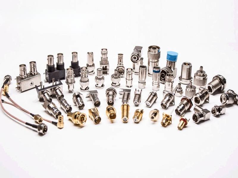
coaxial cable connectors, RF connector types, SMA connector, BNC connector, N-type connector, coaxial cable assemblies, RF cable connectors, coaxial connector guide, RF cable assembly manufacturer, coaxial cable impedance, RF signal connectors, coax cable connectors types, RF connector selection, telecom coax connectors, antenna cable connectors, custom RF cables, coaxial cable assembly supplier, RF engineering connectors, RF connector frequency range, Sino-Conn cable assemblies
Coaxial cable assemblies are a core component of modern communication systems. They connect antennas, transmitters, receivers, testing equipment, and countless electronic devices that rely on stable radio-frequency (RF) signals. While the cable itself carries the signal, the connector is the critical interface that links the cable to electronic equipment. If the connector is poorly chosen or incorrectly installed, signal reflections, attenuation, or interference may occur.
In RF systems, connectors must maintain stable impedance, strong shielding, and reliable mechanical connections. Engineers selecting connectors must consider factors such as frequency range, cable type, installation environment, and system impedance. Because each application has different requirements, several connector types have become industry standards in coaxial cable assemblies.
The most commonly used connectors in coaxial cable assemblies include SMA, BNC, N-type, TNC, and F connectors. Each connector type is designed for specific frequency ranges, impedance requirements, and applications such as telecommunications, broadcast systems, RF testing equipment, and antenna connections. Choosing the correct connector ensures stable signal transmission, minimal signal loss, and long-term reliability in RF communication systems.
For engineers designing RF systems, the connector often determines whether a coaxial cable assembly will perform reliably over time. Many equipment failures attributed to cables are actually caused by incorrect connector selection. One telecom engineer once shared that replacing a mismatched connector reduced signal loss by nearly 20% in their antenna system. Understanding connector types and their applications can therefore make a measurable difference in system performance.
What Are Coaxial Cable Connectors?
Coaxial cable connectors are precision components used to terminate coaxial cables and connect them to RF equipment such as antennas, transmitters, receivers, routers, base stations, testing instruments, and communication modules. Their main function is to create a stable electrical and mechanical interface between the coaxial cable and the device while maintaining the cable’s electrical characteristics, especially impedance and shielding continuity.

In RF transmission systems, signals are carried through the center conductor of the coaxial cable and protected by the outer shielding layer. The connector must extend this structure without changing the internal geometry of the cable. If the connector structure is poorly designed or incorrectly installed, signal reflections, interference, and power loss can occur. Because RF signals often operate at high frequencies, even small dimensional changes inside the connector can influence signal performance.
For engineers designing RF systems, coaxial connectors are not simply mechanical accessories. They are part of the signal transmission path and must match the cable type, frequency range, and impedance of the system.
What Is the Structure of Coaxial Cable Connectors
A coaxial connector typically follows the same structural concept as the cable itself. It maintains concentric alignment between the signal conductor and the shielding layer to preserve signal integrity.
A standard coaxial connector includes the following elements.
| Connector Component | Function |
|---|---|
| Center contact (pin or socket) | Carries the RF signal |
| Dielectric insulator | Maintains spacing between conductors |
| Outer conductor | Provides shielding continuity |
| Connector body | Mechanical support and grounding |
| Coupling mechanism | Secures connection to equipment |
The center conductor transfers the RF signal, while the outer conductor provides electromagnetic shielding. Between these two conductors is a dielectric material, often PTFE (Teflon), which maintains the correct spacing required to achieve a stable impedance.
Maintaining this structure is critical because RF systems rely on consistent impedance. If the distance between the conductors changes inside the connector, impedance will change and signal reflections can occur.
Why Coaxial Connectors Must Match System Impedance
Most coaxial cable systems are designed around specific impedance values. The two most common standards are 50 ohms and 75 ohms.
| Application | Typical Impedance |
|---|---|
| RF communication equipment | 50 Ω |
| Antenna systems | 50 Ω |
| Broadcast video systems | 75 Ω |
| Cable television networks | 75 Ω |
A connector must match the impedance of the cable and equipment. When the impedance is inconsistent, signal reflections occur. This can reduce transmission efficiency and affect system stability.
Engineers often evaluate impedance matching using Voltage Standing Wave Ratio (VSWR).
| VSWR Range | Performance |
|---|---|
| 1.0 – 1.2 | Excellent signal transmission |
| 1.2 – 1.5 | Acceptable performance |
| Above 1.5 | Significant signal reflection |
High-quality connectors are manufactured with precise internal dimensions so they maintain impedance consistency with the coaxial cable.
How Coaxial Connectors Maintain RF Signal Integrity
RF signals behave differently from low-frequency electrical signals. At high frequencies, signals travel along the surface of conductors and are highly sensitive to mechanical changes in the transmission path.
For example, if the connector interface is not perfectly aligned with the cable shielding, the RF signal may leak or reflect. Even small gaps in the shielding can allow electromagnetic interference to enter the system.
Several connector design features help preserve signal integrity.
| Design Feature | Benefit |
|---|---|
| Continuous shielding | Reduces electromagnetic interference |
| Precision center contacts | Maintains stable signal path |
| Controlled dielectric spacing | Maintains impedance |
| Threaded or locking coupling | Ensures stable mechanical connection |
These design elements allow coaxial connectors to transmit RF signals efficiently across wide frequency ranges.
Where Coaxial Cable Connectors Are Used
Coaxial connectors are widely used in industries that depend on stable RF signal transmission.
| Industry | Example Applications |
|---|---|
| Telecommunications | Base stations, wireless infrastructure |
| Satellite communication | Ground stations and receivers |
| Broadcast systems | RF transmitters and antennas |
| Aerospace and defense | Radar and navigation systems |
| Electronics testing | Oscilloscopes and spectrum analyzers |
For example, telecommunications base stations often rely on N-type connectors to connect antenna cables because they provide strong mechanical stability and weather resistance. Laboratory test equipment frequently uses SMA connectors due to their excellent high-frequency performance.
How Engineers Specify Coaxial Connectors
In most RF projects, engineers determine connector specifications during the system design phase. Several parameters are considered before selecting the connector type.
| Parameter | Why It Matters |
|---|---|
| Operating frequency | Determines connector capability |
| Cable diameter | Must match connector size |
| Impedance | Must match cable and device |
| Environment | Indoor or outdoor use |
| Mechanical durability | Number of mating cycles |
For example, an RF communication module operating at 10 GHz will likely require connectors such as SMA or N-type because lower-frequency connectors may introduce signal loss at those frequencies.
In many real-world projects, customers initially contact manufacturers with only partial information. Sometimes they provide a connector model number, and sometimes only a photo of an existing cable assembly. Engineers then identify the connector type and determine the appropriate cable specification based on system requirements.
Which Connectors Are Common in Coaxial Cable Assemblies?
Several connector types have become standard in coaxial cable assemblies because they provide stable impedance control, reliable shielding, and durable mechanical connections. Different connectors are designed for different frequency ranges, installation environments, and cable types. Engineers typically select connector types based on system frequency, cable diameter, installation conditions, and long-term reliability requirements.
In real RF projects, the connector choice often depends on the device interface. For example, laboratory test instruments frequently use SMA connectors, while antenna infrastructure often relies on N-type connectors. Broadcast and measurement equipment often use BNC connectors because they allow quick installation.
The most widely used connectors in coaxial cable assemblies include SMA, BNC, N-type, TNC, and F connectors. Each type has unique electrical characteristics and mechanical structures.
| Connector Type | Typical Frequency Range | Impedance | Common Applications |
|---|---|---|---|
| SMA | Up to 18 GHz | 50 Ω | RF modules, testing equipment |
| BNC | Up to 4 GHz | 50 / 75 Ω | Video systems, oscilloscopes |
| N-type | Up to 11 GHz | 50 Ω | Antennas, telecom systems |
| TNC | Up to 11 GHz | 50 Ω | Wireless communication |
| F-type | Up to 3 GHz | 75 Ω | Cable TV, broadcast systems |
Understanding how these connectors work helps engineers choose the right interface for their coaxial cable assemblies.
Which SMA Connectors
SMA connectors are widely used in high-frequency coaxial cable assemblies. They are compact threaded connectors designed for RF systems that require stable signal transmission at microwave frequencies.
Typical SMA connectors support frequencies up to 18 GHz, and precision versions can operate even higher depending on the design and cable type.
| Parameter | SMA Connector |
|---|---|
| Frequency capability | Up to 18 GHz |
| Impedance | 50 Ω |
| Coupling mechanism | Threaded |
| Size | Compact |
| Typical cables | RG316, RG174 |

SMA connectors are commonly used in:
- RF modules
- wireless communication equipment
- signal generators
- spectrum analyzers
- laboratory testing systems
The threaded coupling mechanism ensures a secure mechanical connection that resists vibration. Because of their small size and high-frequency capability, SMA connectors are often used in equipment where space is limited but signal performance is critical.
However, SMA connectors require careful installation. Overtightening the connector can damage the center contact, which may affect signal transmission.
Which BNC Connectors
BNC connectors are among the most recognizable coaxial connectors and are widely used in measurement equipment and broadcast systems. The name “BNC” refers to Bayonet Neill–Concelman, which describes the connector’s locking mechanism.
Unlike threaded connectors, BNC connectors use a bayonet locking system that allows quick connection and disconnection.
| Parameter | BNC Connector |
|---|---|
| Frequency capability | Up to 4 GHz |
| Impedance options | 50 Ω or 75 Ω |
| Coupling mechanism | Bayonet lock |
| Typical cables | RG58, RG59 |

BNC connectors are commonly found in:
- oscilloscopes
- video signal equipment
- laboratory test instruments
- surveillance systems
The quick-lock design makes BNC connectors convenient in testing environments where cables are frequently connected and disconnected.
However, because the locking mechanism is not threaded, BNC connectors are less resistant to vibration compared with threaded connectors like SMA or N-type.
Which N-Type Connectors
N-type connectors are designed for higher power RF applications and outdoor installations. They feature a threaded coupling mechanism that provides strong mechanical stability and good environmental resistance.
N-type connectors were originally developed for military radar systems and later became widely used in telecommunications infrastructure.
| Parameter | N-Type Connector |
|---|---|
| Frequency capability | Up to 11 GHz |
| Impedance | 50 Ω |
| Coupling mechanism | Threaded |
| Typical cables | LMR400, RG213 |

N-type connectors are commonly used in:
- cellular base stations
- antenna systems
- RF transmitters
- wireless infrastructure
Because of their larger size and durable construction, N-type connectors are well suited for outdoor environments where connectors must withstand vibration, moisture, and temperature variations.
Many telecom antenna cables use N-type connectors because they maintain stable impedance and shielding even in harsh conditions.
Which TNC Connectors
TNC connectors are essentially a threaded version of the BNC connector. The threaded coupling provides improved mechanical stability and better performance at higher frequencies.
| Parameter | TNC Connector |
|---|---|
| Frequency capability | Up to 11 GHz |
| Impedance | 50 Ω |
| Coupling mechanism | Threaded |
| Typical cables | RG58, RG142 |

TNC connectors are commonly used in:
- wireless communication equipment
- mobile radio systems
- GPS antennas
Because of their threaded design, TNC connectors provide better resistance to vibration compared with BNC connectors. This makes them suitable for applications such as vehicle-mounted communication systems where connectors may experience movement or mechanical stress.
Which F Connectors
F connectors are widely used in consumer coaxial cable systems, especially for television and broadband communication networks. They are designed primarily for 75-ohm systems.
| Parameter | F Connector |
|---|---|
| Frequency capability | Up to 3 GHz |
| Impedance | 75 Ω |
| Coupling mechanism | Threaded |
| Typical cables | RG6, RG59 |

F connectors are commonly used in:
- cable television systems
- satellite receivers
- broadband internet installations
One unique feature of F connectors is that the cable’s center conductor often serves as the connector pin. This simplifies installation and reduces manufacturing cost.
Although F connectors are widely used in residential systems, they are less common in professional RF engineering applications because they are optimized primarily for lower frequency broadcast signals.
Why Different Connectors Are Used in Different Systems
The reason multiple connector types exist is that RF systems operate under very different conditions. A connector that performs well in one application may not perform well in another.
For example:
| Application | Preferred Connector |
|---|---|
| RF test equipment | SMA |
| Antenna infrastructure | N-type |
| Video signal equipment | BNC |
| Mobile radio systems | TNC |
| Cable television | F-type |
Engineers therefore select connectors not only based on electrical specifications but also on installation environment, durability requirements, and compatibility with existing equipment.
When selecting connectors for coaxial cable assemblies, manufacturers must also ensure that the connector is compatible with the cable type and termination method. Proper connector selection and installation are essential to maintain signal integrity and long-term system reliability.
How Do You Choose the Right Coaxial Cable Connector?
Choosing the right coaxial cable connector is one of the most important decisions in RF cable assembly design. Even if the cable itself meets electrical specifications, using an incompatible connector can introduce signal reflections, power loss, or unstable connections. Engineers therefore evaluate several practical factors before selecting a connector, including operating frequency, system impedance, cable type, installation environment, and mechanical durability.
In real engineering projects, connector selection usually starts from the equipment interface. Many devices already define the connector interface on the equipment side. The cable assembly must match that connector type while also ensuring compatibility with the selected coaxial cable.
When selecting connectors, engineers typically review the following parameters.
| Selection Factor | Why It Matters |
|---|---|
| Operating frequency | Determines connector electrical capability |
| System impedance | Must match cable and equipment |
| Cable diameter | Ensures correct connector termination |
| Installation environment | Influences connector durability |
| Mechanical reliability | Determines long-term connection stability |
Making the correct connector choice ensures the cable assembly will transmit RF signals efficiently and operate reliably in its intended environment.
How Frequency Affects Connector Choice
Frequency range is one of the first factors engineers consider when selecting a coaxial cable connector. RF connectors are designed with specific internal geometries that allow them to operate efficiently within certain frequency ranges.
As signal frequency increases, connectors must maintain tighter dimensional tolerances to prevent signal reflections and attenuation.
| Connector Type | Maximum Typical Frequency |
|---|---|
| F-type | ~3 GHz |
| BNC | ~4 GHz |
| N-type | ~11 GHz |
| TNC | ~11 GHz |
| SMA | ~18 GHz |

For example, a wireless communication system operating at 5 GHz would generally require SMA, TNC, or N-type connectors rather than BNC connectors, which are more commonly used at lower frequencies.
Higher-frequency connectors typically use threaded coupling mechanisms and more precise internal structures to maintain impedance control. These connectors also often include high-quality dielectric materials such as PTFE to stabilize signal transmission.
When engineers design RF systems, they usually select connectors with frequency ratings higher than the system’s operating frequency. This helps maintain signal stability and reduces the risk of performance degradation over time.
How Impedance Matching Affects Connector Selection
Impedance matching is critical in coaxial cable systems because RF signals behave like waves traveling through a transmission line. If the impedance changes at any point in the system—such as the connector interface—part of the signal will reflect back toward the source.
Most RF communication systems use 50-ohm impedance, while broadcast and video systems typically use 75-ohm impedance.
| Application Type | Standard Impedance |
|---|---|
| RF communication equipment | 50 Ω |
| Antenna systems | 50 Ω |
| Broadcast video systems | 75 Ω |
| Cable television networks | 75 Ω |
Using the wrong impedance connector can cause signal reflections that reduce system efficiency. Engineers often evaluate this effect using return loss or Voltage Standing Wave Ratio (VSWR) measurements.
| VSWR Value | Performance Level |
|---|---|
| 1.0–1.2 | Excellent signal match |
| 1.2–1.5 | Acceptable performance |
| >1.5 | Signal reflection likely |
For example, installing a 75-ohm connector in a 50-ohm RF communication system can introduce impedance mismatch and increase signal loss.
Connector manufacturers therefore design connectors with precise internal dimensions to maintain consistent impedance across the cable assembly.
How Cable Type Determines Connector Compatibility
Coaxial cables vary widely in diameter, conductor size, shielding structure, and dielectric materials. Connectors must be specifically designed to terminate the selected cable type.
Each cable has a specific outer diameter and conductor structure that must match the connector termination method.
| Cable Type | Typical Use |
|---|---|
| RG174 | Compact RF devices |
| RG316 | High-frequency equipment |
| RG58 | General RF communication |
| LMR400 | Long-distance RF transmission |

If the connector does not match the cable structure, the termination may damage the shielding or dielectric layer, leading to signal leakage or increased attenuation.
Proper connector termination techniques are also important. These may include:
- crimp termination
- solder termination
- compression fittings
Professional cable assembly manufacturers use calibrated crimp tools and controlled assembly procedures to ensure reliable connector installation.
How Installation Environment Influences Connector Choice
The operating environment can strongly influence which connector type is most appropriate. Connectors used indoors in laboratory equipment may prioritize convenience, while outdoor connectors must withstand harsh environmental conditions.
| Environment Condition | Connector Requirement |
|---|---|
| Outdoor installations | Weather-resistant connectors |
| High vibration areas | Threaded coupling |
| Frequent reconnections | Quick-lock connectors |
| High humidity | Corrosion-resistant materials |
For example, N-type connectors are widely used in antenna installations because they provide strong mechanical stability and good sealing performance against moisture.
In contrast, BNC connectors are commonly used in laboratory equipment because they allow quick connection and disconnection during testing.
Understanding the operating environment helps engineers choose connectors that will remain reliable under real operating conditions.
How Mechanical Reliability Affects Connector Selection
Mechanical durability is another important factor when choosing coaxial cable connectors. Some connectors are designed for frequent connection cycles, while others are optimized for permanent installations.
Connector durability is often measured by the number of mating cycles it can withstand.
| Connector Type | Typical Mating Cycles |
|---|---|
| SMA | ~500 cycles |
| BNC | ~500 cycles |
| N-type | ~500 cycles |
| TNC | ~500 cycles |
In applications such as laboratory testing, connectors may be connected and disconnected many times per day. In these cases, connectors must maintain stable electrical contact even after repeated use.
Mechanical reliability also includes resistance to vibration and accidental cable movement. Threaded connectors generally provide stronger mechanical retention than bayonet-style connectors.
Because connectors are often the most mechanically stressed component in a cable assembly, selecting a durable connector design can significantly extend the service life of the entire cable system.
How Engineers Finalize Connector Selection
In real-world projects, engineers rarely select connectors based on a single factor. Instead, they evaluate the entire system to determine the most suitable connector type.
A typical connector selection process includes the following steps.
| Step | Evaluation |
|---|---|
| Step 1 | Determine system frequency |
| Step 2 | Confirm impedance requirement |
| Step 3 | Identify compatible cable type |
| Step 4 | Evaluate installation environment |
| Step 5 | Verify mechanical durability |
Once these parameters are confirmed, engineers select the connector type that best matches the application requirements.
In many cases, customers approach cable assembly manufacturers with only partial information—sometimes only a connector model number or a picture of an existing cable. Experienced manufacturers can analyze these inputs and recommend suitable connectors and cable combinations.
Choosing the right coaxial connector ensures that the cable assembly will maintain stable signal transmission, reliable mechanical performance, and long service life within the RF system.
What Connector Features Affect Coaxial Cable Performance?
In coaxial cable assemblies, the connector is not just a mechanical interface—it is part of the RF transmission path. Every RF signal that travels through a coaxial cable must pass through the connector interface before entering a device or antenna. If the connector is poorly designed, improperly installed, or incompatible with the cable, the entire system may experience signal loss, interference, or unstable performance.
Several structural and electrical characteristics of connectors directly affect coaxial cable performance. Engineers therefore pay close attention to parameters such as impedance consistency, shielding structure, connector materials, and mechanical durability.
In many real-world RF systems, signal problems are not caused by the cable itself but by connector-related issues such as poor termination, impedance mismatch, or shielding discontinuity. Understanding these connector features helps engineers design cable assemblies that maintain stable signal transmission across the entire system.
| Connector Feature | Impact on Performance |
|---|---|
| Impedance control | Prevents signal reflections |
| Shielding continuity | Reduces electromagnetic interference |
| Contact materials | Maintains stable conductivity |
| Mechanical structure | Ensures reliable connection |
These features work together to maintain the electrical integrity of the coaxial cable assembly.
What Impedance Matching Does
Impedance matching is one of the most important electrical characteristics of coaxial connectors. Coaxial cable systems are designed to maintain a constant impedance along the entire transmission path. If the impedance changes at any point—such as inside a connector—the RF signal will partially reflect back toward the source.
This reflection reduces transmission efficiency and can introduce noise into the system.
Most RF communication systems operate at 50 ohms, while broadcast and video systems typically use 75 ohms impedance.
| System Type | Standard Impedance |
|---|---|
| RF communication systems | 50 Ω |
| Antenna systems | 50 Ω |
| Broadcast video | 75 Ω |
| Cable TV networks | 75 Ω |

Connector manufacturers maintain impedance by carefully controlling the internal geometry of the connector. The spacing between the center conductor and the outer conductor must match the structure of the coaxial cable.
Even small variations in this spacing can affect impedance. At high frequencies, these variations can cause significant signal reflections.
Engineers often measure impedance performance using return loss or VSWR.
| VSWR Value | Signal Quality |
|---|---|
| 1.0 – 1.2 | Excellent |
| 1.2 – 1.5 | Good |
| Above 1.5 | Signal reflection likely |
Precision RF connectors maintain tight manufacturing tolerances so that the impedance remains consistent throughout the connector and cable interface.
What Shielding Design Does
Shielding plays a critical role in protecting RF signals from electromagnetic interference (EMI). Coaxial cables are designed with an outer conductor that shields the internal signal path from external electrical noise.
The connector must extend this shielding structure without creating gaps or weak points.
If shielding continuity is interrupted at the connector interface, external electromagnetic signals may enter the cable assembly and degrade signal quality.
Common shielding problems include:
| Shielding Issue | Result |
|---|---|
| Shield discontinuity | Increased EMI noise |
| Weak connector body | Reduced shielding effectiveness |
| Poor termination | Signal leakage |
High-quality RF connectors maintain continuous shielding between the cable braid and the connector body. This ensures that the signal path remains protected from external interference.
Shielding is especially important in environments where multiple electronic devices operate close together, such as telecommunications equipment rooms or industrial control systems.
What Connector Materials Matter
The materials used in coaxial connectors directly affect electrical performance, corrosion resistance, and long-term reliability.
Several materials are commonly used in connector construction.
| Connector Component | Common Material |
|---|---|
| Connector body | Brass or stainless steel |
| Center contact | Gold-plated brass |
| Dielectric insulator | PTFE (Teflon) |
| Plating layer | Nickel or gold |
Gold plating is widely used on the center contact because it provides excellent electrical conductivity and corrosion resistance. This helps maintain stable signal transmission over time.
PTFE dielectric materials are used inside many RF connectors because they maintain consistent electrical properties across wide temperature ranges.
Connector body materials such as brass or stainless steel provide mechanical strength and durability.
Material selection becomes especially important in environments where connectors may be exposed to moisture, temperature changes, or corrosive conditions.
What Connector Durability Matters
Mechanical durability also influences the long-term performance of coaxial cable assemblies. Connectors must maintain stable electrical contact even after repeated use, vibration, or cable movement.
Connector durability is often measured by the number of mating cycles the connector can withstand.
| Connector Type | Typical Mating Cycles |
|---|---|
| SMA | ~500 cycles |
| BNC | ~500 cycles |
| N-type | ~500 cycles |
| TNC | ~500 cycles |
In laboratory environments, connectors may be connected and disconnected many times during testing. Durable connectors maintain reliable electrical contact even after repeated cycles.
Mechanical durability also includes resistance to vibration. Threaded connectors such as SMA or N-type generally provide stronger retention than quick-lock connectors.
A connector that loosens during operation can cause intermittent signal interruptions, which may lead to unreliable system performance.
Why Connector Termination Quality Matters
Even the best connector design cannot deliver reliable performance if the connector is not properly installed on the cable.
Connector termination involves attaching the cable’s center conductor, dielectric, and shielding layers to the connector structure. This process must maintain the coaxial geometry of the cable.
Common termination problems include:
| Termination Issue | Performance Impact |
|---|---|
| Poor crimping | Increased resistance |
| Misaligned center pin | Signal distortion |
| Damaged dielectric | Impedance variation |
| Incomplete shielding contact | EMI interference |
Professional cable assembly manufacturers use specialized tools and controlled procedures to ensure accurate connector termination.
In many production environments, manufacturers perform several inspections during assembly to verify connector quality.
For example, cable assembly factories may conduct:
- process inspection during connector termination
- electrical testing after assembly
- final inspection before shipment
These inspection steps help ensure that each coaxial cable assembly maintains stable electrical and mechanical performance.
How Do Manufacturers Support Custom Coaxial Cable Assemblies?
Custom coaxial cable assemblies are rarely “off-the-shelf” products. In most RF systems—such as telecommunications equipment, antennas, signal testing instruments, radar systems, or industrial electronics—the cable assembly must match very specific connector models, cable structures, impedance requirements, and installation environments. Because of these variables, cable assembly manufacturers play an important role in translating a customer’s technical requirements into a reliable, production-ready cable solution.
In real projects, customers often approach manufacturers with different levels of technical information. Some engineers provide full drawings, impedance requirements, and connector specifications. Others may only provide a connector model number, cable type, or even a photo of an existing cable assembly. Manufacturers must analyze these inputs and determine the appropriate cable structure, connector termination method, and production process.
A professional coaxial cable assembly manufacturer typically supports customization through engineering consultation, drawing development, prototype production, and strict quality control.
| Development Stage | What the Manufacturer Provides |
|---|---|
| Requirement review | Evaluate connectors, cables, and system requirements |
| Engineering drawing | Provide detailed cable assembly drawings |
| Sample production | Produce prototype cable assemblies |
| Testing verification | Confirm electrical and mechanical performance |
| Mass production | Manufacture stable, repeatable assemblies |
This process helps ensure that the final cable assembly meets both electrical performance standards and practical installation requirements.
How Connector and Cable Matching Works
One of the first tasks manufacturers perform is ensuring that the selected connectors are compatible with the chosen coaxial cable. Coaxial cables differ in outer diameter, shielding structure, conductor size, and dielectric materials. If a connector does not match the cable structure, the termination may damage the cable or compromise signal integrity.
For example, the following cable types require different connector sizes and termination methods.
| Cable Type | Typical Outer Diameter | Common Connector Types |
|---|---|---|
| RG174 | ~2.8 mm | SMA, BNC |
| RG316 | ~2.5 mm | SMA, TNC |
| RG58 | ~5 mm | BNC, TNC |
| LMR400 | ~10 mm | N-type |

If the connector inner dimensions do not match the cable, several problems may occur:
- shielding may not properly contact the connector body
- the center conductor may not align with the connector pin
- impedance discontinuities may occur
Manufacturers therefore verify the compatibility between cable type and connector model before assembly begins.
This matching process ensures that the coaxial cable maintains consistent impedance and shielding performance across the connector interface.
How Engineering Drawings Help Define Cable Assemblies
Engineering drawings are essential for ensuring that both the manufacturer and the customer understand the exact cable assembly configuration before production begins.
A typical coaxial cable assembly drawing includes several important parameters.
| Drawing Element | Description |
|---|---|
| Connector model | Specific connector part number |
| Cable type | RG or LMR cable specification |
| Cable length | Overall assembly length |
| Termination type | Crimp, solder, or compression |
| Assembly structure | Straight or right-angle connectors |
These drawings help engineers verify that the cable assembly will fit within the equipment and perform as expected.

In many projects, drawings also show the pin configuration and shielding structure, allowing engineers to review how the RF signal will travel through the cable assembly.
At Sino-Conn, engineering teams typically prepare cable assembly drawings within 1–3 days depending on complexity. In urgent situations, preliminary drawings can sometimes be provided within 30 minutes to help customers quickly confirm design details.
Customers usually review and approve the drawing before production begins, ensuring that the final cable assembly matches the intended system configuration.
How Rapid Sample Production Supports Engineering Projects
Prototype samples are an important step in RF cable development. Before committing to large production volumes, engineers often test sample cable assemblies in their equipment to verify performance.
Sample testing allows customers to evaluate several aspects of the cable assembly.
| Test Category | Purpose |
|---|---|
| Electrical testing | Verify RF signal performance |
| Mechanical fit | Confirm connector compatibility |
| Environmental durability | Evaluate resistance to vibration or temperature |
| System integration | Test cable inside real equipment |
For example, when integrating a new antenna system, engineers may test several cable assemblies with different connector types to determine which configuration delivers the best signal performance.
Rapid sample production helps shorten product development timelines. Waiting several weeks for prototypes can delay equipment development or system integration testing.
At Sino-Conn, standard sample lead times are typically around two weeks, while urgent prototype requests can sometimes be completed within 2–3 days, depending on connector availability and project complexity.
This flexibility helps engineers quickly validate cable designs and move forward with system development.
How Manufacturers Maintain Consistent Cable Assembly Quality
Quality control is critical in coaxial cable assembly manufacturing because small defects can significantly affect RF performance. Improper connector installation, shielding gaps, or damaged dielectric materials can introduce signal reflections or interference.
Professional cable assembly manufacturers therefore implement several inspection steps during production.
| Inspection Stage | Purpose |
|---|---|
| Process inspection | Verify connector termination accuracy |
| Electrical testing | Confirm impedance and signal continuity |
| Final inspection | Check assembly structure and connectors |
| Pre-shipment inspection | Ensure product reliability |
These inspections help identify potential defects before the cable assemblies reach the customer.
Electrical testing often includes measurements such as continuity testing and impedance verification to ensure the cable assembly maintains stable signal transmission.
Mechanical inspection may also confirm that connectors are securely attached and that the cable jacket has not been damaged during assembly.
At Sino-Conn, the production process includes three inspection stages: process inspection, final inspection, and pre-shipment inspection, ensuring that each coaxial cable assembly meets both electrical and mechanical requirements.
How Sino-Conn Supports Custom Cable Assembly Projects
Custom cable assembly projects often involve multiple technical considerations, including connector selection, cable compatibility, impedance requirements, and installation conditions. Manufacturers that understand these factors can help customers avoid common design mistakes.
Sino-Conn works with customers from various industries including telecommunications, industrial electronics, and RF testing equipment. Many customers approach the company with different types of requests.
Some customers provide detailed engineering drawings and specifications. Others may only send a connector model number or a photo of an existing cable assembly.
The engineering team evaluates these requests and recommends appropriate cable assembly solutions based on the application requirements.
Several capabilities help support these projects.
| Capability | Description |
|---|---|
| Rapid quotation | Accurate quotation within about 30 minutes |
| Engineering support | Assistance selecting connectors and cables |
| Drawing support | CAD-to-PDF drawings provided quickly |
| Flexible MOQ | Production starting from a single piece |
| Lead time flexibility | Fast sample and production schedules |
Conclusion
Coaxial cable assemblies play a vital role in modern communication systems, RF equipment, testing instruments, and antenna installations. While the cable itself carries the signal, the connector determines how efficiently that signal enters and exits the system.
Understanding the differences between common connectors such as SMA, BNC, N-type, TNC, and F connectors allows engineers and procurement teams to select the right interface for their applications. Factors such as operating frequency, impedance matching, cable compatibility, and environmental conditions all influence connector selection.
Equally important is choosing a reliable cable assembly manufacturer. Proper connector termination, precise impedance control, and strict quality inspection procedures ensure that cable assemblies deliver consistent performance over time.
Sino-Conn works closely with engineers, OEM manufacturers, and distributors to provide customized coaxial cable assemblies tailored to specific project requirements. Whether customers provide detailed engineering drawings or only a connector reference, the engineering team helps transform these requirements into production-ready cable assemblies.
With rapid drawing support, flexible customization, and comprehensive quality control, Sino-Conn helps customers develop reliable RF cable solutions for telecommunications, electronics, and industrial applications.
If you are developing a new RF system or searching for a reliable coaxial cable assembly supplier, Sino-Conn welcomes your inquiry. Share your connector models, cable requirements, or project drawings, and our engineering team will help design a cable assembly solution that fits your application.


