 Skip to content
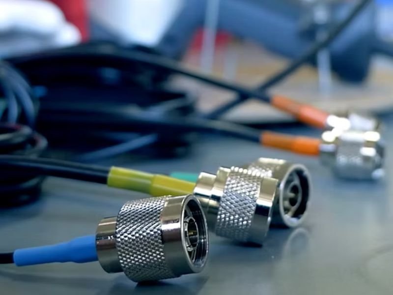
High-frequency signals are extremely sensitive to material quality. A small change in conductor plating, insulation material, or shielding structure can dramatically influence impedance stability, attenuation, and electromagnetic interference. That is why RF cable assemblies are not simply wires with connectors attached. They are carefully engineered transmission systems where each material choice affects signal performance, durability, and reliability.
For engineers and procurement teams sourcing RF cable assemblies, understanding the materials inside the cable is critical. It helps evaluate product quality, predict signal behavior, and ensure compatibility with demanding applications such as wireless infrastructure, medical equipment, aerospace electronics, and high-speed communication systems.
RF cable assemblies are typically built using several key materials: copper or silver-plated conductors for signal transmission, dielectric insulation such as PTFE or PE to maintain impedance, shielding layers like aluminum foil and braided copper to block EMI, metal connectors often plated with gold or nickel for signal integrity, and protective outer jackets such as PVC, FEP, or LSZH for environmental protection.
In practice, these materials must work together as a system. An experienced RF cable assembly manufacturer understands how to balance electrical performance, mechanical flexibility, cost, and lead time. At Sino-conn, many customers approach us with only a connector model number—or sometimes just a photo of a cable. By analyzing the application requirements, our engineers quickly determine the correct materials and provide a confirmed drawing within hours.
Understanding these materials will help you choose the right RF cable assembly supplier and ensure your design performs exactly as expected.
What Are RF Cable Assemblies?
RF cable assemblies are engineered signal paths made from coaxial cable and RF connectors. Their job is to carry radio frequency signals with controlled impedance, low loss, and strong resistance to external interference. Good RF cable assemblies are not defined by appearance alone. They are defined by how well their internal materials work together under electrical, mechanical, and environmental stress.

What Components Form RF Cable Assemblies
An RF cable assembly is composed of several integrated components working together to maintain signal quality. These components include the center conductor, dielectric insulation, shielding layer, outer jacket, and RF connectors. Each element plays a specific role in maintaining impedance consistency and protecting signals from noise.
The center conductor carries the RF signal. The dielectric maintains spacing and impedance control. Shielding blocks interference, while the outer jacket protects the cable from environmental damage.
For high-frequency applications such as 5G communication, satellite equipment, and radar systems, even minor variations in material thickness or conductivity can affect performance. This is why professional RF cable assembly manufacturers must strictly control materials and production processes.
The table below shows the core structure in a practical way.
| RF Cable Assemblies Part | Main Function | Common Material Choices | Why Customers Should Care |
|---|---|---|---|
| Center conductor | Carries RF signal | Bare copper, silver-plated copper, copper-clad steel | Affects conductivity, attenuation, flexibility |
| Dielectric | Controls spacing and impedance | PTFE, PE, foam PE, FEP | Affects impedance stability and heat resistance |
| Shielding | Reduces EMI and leakage | Copper braid, aluminum foil, silver-plated braid | Affects signal integrity and noise control |
| Connector body/contact | Creates interface with device | Brass, stainless steel, gold plating, nickel plating | Affects mating life, corrosion resistance, contact quality |
| Outer jacket | Protects cable externally | PVC, FEP, PE, LSZH | Affects UV, flame, oil, and temperature resistance |

This structure is consistent across many commercial and industrial RF products, although the exact build changes by frequency, bend requirement, and environment. Amphenol’s coaxial cable guide describes the same core construction, including conductor, dielectric, shield, and jacket.
How Do RF Cable Assemblies Work
RF cable assemblies operate based on the principle of controlled impedance transmission. Most RF cables are designed to maintain a characteristic impedance of 50 ohms or 75 ohms, depending on the application.
The coaxial structure ensures that the electromagnetic field remains contained between the inner conductor and the shielding layer. This design minimizes signal leakage and protects the signal from external interference.
The performance of an RF cable assembly is influenced by several measurable factors:
| Parameter | Typical Value |
|---|---|
| Impedance | 50Ω / 75Ω |
| Frequency Range | DC – 18 GHz or higher |
| Shielding Effectiveness | >90 dB |
| Operating Temperature | -40°C to +200°C |
When these parameters are carefully controlled through proper material selection, RF cable assemblies can transmit signals with extremely low attenuation and high stability.
Where Are RF Cable Assemblies Used
RF cable assemblies appear in far more places than many customers realize. They are common in antennas, wireless equipment, test systems, routers, repeaters, GPS systems, medical electronics, radar equipment, industrial control systems, and aerospace electronics. Amphenol lists telecommunications, test and measurement, industrial connectivity, antenna connections, and patch panels among common RF cable assembly applications.

Different applications push material decisions in different directions. A medical customer may care most about consistency, compliance, and documentation. A military or aerospace project may push for higher shielding performance, better heat resistance, and tighter electrical tolerance. An OEM factory may focus first on price, then lead time, then production capacity. A distributor may mainly need quick identification from an existing part number and a reliable spec sheet.
That is why one RF cable assembly article cannot be only technical. It also needs to be commercial. Customers do not buy conductor metal in isolation. They buy confidence that the assembly will fit their product, arrive on schedule, and perform as promised. In real projects, these are linked.
The table below reflects how different customer types often evaluate RF cable assemblies.
| Customer Type | Main Concern | Material Questions Usually Raised |
|---|---|---|
| Engineer | Performance and feasibility | What conductor, dielectric, and shielding are used? |
| OEM factory | Cost and repeatability | Can material specs stay stable in volume production? |
| Distributor | Fast identification | Is there a matching alternative to the original model? |
| General procurement | Price and lead time | Can this build be quoted quickly with a clear drawing? |
For a supplier like Sino-Conn, understanding these priorities helps close more RF projects. The material explanation must fit the customer’s level of technical depth. Engineers want design logic. Procurement wants risk reduction. OEM clients want a workable cost structure. A good RF cable assembly supplier knows how to speak to all three.
What Conductor Materials Are Used in RF Cable Assemblies?
RF cable assemblies usually use bare copper, silver-plated copper, tinned copper, or copper-clad steel conductors. The right conductor depends on frequency, attenuation target, flexibility, corrosion resistance, and budget. In many higher-frequency RF cable assemblies, silver-plated copper is chosen because surface conductivity matters more as frequency rises.
Which Metals Are Used in RF Cable Assemblies
The conductor is the first place many technical customers look, and for good reason. If the conductor material is weak, the rest of the cable cannot fully compensate for it. In RF cable assemblies, the most common conductor materials are bare copper, silver-plated copper, tinned copper, and copper-clad steel. Each one has a practical reason for being used.
Bare copper is the most common starting point because it offers high conductivity and good flexibility at a reasonable cost. Tinned copper adds corrosion resistance and can be useful in more demanding environments where oxidation is a concern. Silver-plated copper is widely used in higher-frequency assemblies because RF current tends to flow near the conductor surface. Copper-clad steel is sometimes selected when mechanical strength matters, though it is not the first choice for many high-performance low-loss applications.
The data sheets returned by Times Microwave and Pasternack repeatedly show silver-plated copper in RF and microwave cable constructions, especially where frequency, shielding quality, and temperature performance are critical.
The most widely used conductor materials in RF cable assemblies include:
| Conductor Material in RF Cable Assemblies | Main Strength | Main Limitation | Good Fit For |
|---|---|---|---|
| Bare copper | High conductivity, good flexibility, cost-effective | Surface oxidation over time | General RF assemblies, commercial equipment |
| Silver-plated copper | Excellent surface conductivity, strong high-frequency performance | Higher cost | Microwave, aerospace, test systems |
| Tinned copper | Better corrosion resistance | Not the best choice for top RF performance | Harsh environments, general industrial use |
| Copper-clad steel | Higher tensile strength | Lower conductivity than copper-rich options | Certain long-run or mechanically demanding builds |
For a customer asking for a quote, this matters because conductor choice can change both price and electrical behavior. A cable that seems cheaper at first may lose that advantage if it creates more attenuation or fails environmental testing later.

How Does Copper Improve RF Cable Assemblies
Copper is widely used in RF cable assemblies because it offers a strong balance of conductivity, mechanical flexibility, and cost efficiency.
Its conductivity rating is approximately 58 MS/m, making it one of the best materials for signal transmission. Copper also allows cables to bend repeatedly without cracking, which is important in applications where cables must move or flex during operation.
From a manufacturing perspective, copper conductors are easy to process during cable drawing, plating, and connector termination. This reduces production complexity and ensures stable quality.
For many OEM manufacturers, copper conductors also provide a reliable cost-performance ratio. While alternative materials exist, few offer the same balance of electrical performance and manufacturability.
Are Silver Conductors Used in RF Cable Assemblies
Yes, silver-plated conductors are widely used in RF cable assemblies, especially when performance expectations are high. This is not because the whole cable suddenly becomes exotic. It is because high-frequency current concentrates near the conductor surface. If the surface is more conductive, the signal path becomes more efficient. That is why silver-plated copper shows up repeatedly in RF and microwave cable data sheets from established manufacturers. Times Microwave lists silver-plated copper center conductors in products such as SF-316, RG-223, and MAXGAIN cable families.
This does not mean every project needs silver plating. That would raise cost without always creating real customer value. The right question is where silver-plated conductors actually help enough to justify the premium. In many projects, the answer is high-frequency test systems, aerospace electronics, radar, satellite hardware, military communication, and other applications where performance margin is tight and electrical consistency matters more than lowest unit price.
There is another practical advantage. Silver plating also helps resist oxidation better than plain untreated surfaces in certain service conditions. Over time, that can support more stable performance and easier long-term qualification.
For Sino-Conn customers, the discussion often comes down to three points. What frequency range must the assembly support? What environment will it live in? What cost target must the project meet? Once those three are clear, conductor choice becomes much easier. Sometimes the right answer is original-spec silver-plated construction. Sometimes a more economical alternative can meet the real application need without overdesigning the product.
Here is a quick reference many customers find useful.
| Project Need | More Suitable Conductor Direction |
|---|---|
| Lowest reasonable cost | Bare copper |
| Better corrosion resistance | Tinned copper |
| Higher RF performance | Silver-plated copper |
| Higher mechanical strength | Copper-clad steel |
What Dielectric Materials Are Used in RF Cable Assemblies?
Dielectric insulation is the material placed between the center conductor and the shielding layer in an RF cable assembly. Its main role is to maintain stable spacing between conductors and to control the cable’s characteristic impedance. Without a stable dielectric material, RF signals can suffer from impedance fluctuation, increased attenuation, and signal reflection.
Common dielectric materials used in RF cable assemblies include PTFE, polyethylene (PE), foam polyethylene, and FEP. Each of these materials offers different advantages in terms of electrical stability, temperature resistance, flexibility, and cost. The choice depends heavily on the cable’s operating frequency, environmental conditions, and mechanical requirements.
For customers selecting RF cable assemblies, dielectric materials often determine the cable’s long-term reliability. While conductors carry the signal, the dielectric ensures that the signal travels in a controlled electromagnetic field. Poor dielectric stability can cause signal distortion even if the conductor itself is high quality.
What Is Dielectric in RF Cable Assemblies
In an RF cable assembly, the dielectric material fills the space between the center conductor and the shielding layer. This spacing is critical because the impedance of a coaxial cable is determined by the relationship between conductor diameter, shield diameter, and the dielectric constant of the insulation material.
A stable dielectric ensures that the cable maintains its designed impedance, most commonly 50 ohms or 75 ohms. If the dielectric compresses, melts, or changes structure under temperature or mechanical stress, impedance can shift and signal reflections increase.
Dielectric materials also influence signal propagation speed. The velocity factor of a cable describes how fast signals travel compared with the speed of light. Different dielectric materials produce different velocity factors.
| Dielectric Material | Typical Dielectric Constant | Velocity Factor | Temperature Range |
|---|---|---|---|
| Polyethylene (PE) | ~2.25 | ~66% | -40°C to 80°C |
| Foam Polyethylene | ~1.5 | ~80–85% | -40°C to 85°C |
| PTFE | ~2.1 | ~70% | -65°C to 200°C |
| FEP | ~2.1 | ~70% | -65°C to 200°C |
For engineers designing RF systems, dielectric stability is essential for maintaining consistent electrical performance. A cable that performs well at room temperature may behave very differently in a high-temperature enclosure if the dielectric is not suitable.
Which Insulation Materials RF Cable Assemblies Use
Several dielectric materials are widely used in RF cable assemblies, each serving a specific range of applications.
Polyethylene (PE) is one of the most common dielectric materials. It offers good electrical stability at a relatively low cost and is widely used in general communication cables and standard RF assemblies.
Foam polyethylene is used when lower signal attenuation is needed. By introducing microscopic air pockets into the dielectric, the effective dielectric constant is reduced. Lower dielectric constant means faster signal propagation and lower loss.
PTFE (Polytetrafluoroethylene) is often chosen for high-performance RF applications. It provides excellent electrical stability and can withstand extremely high temperatures. PTFE is frequently used in aerospace electronics, microwave equipment, and laboratory testing cables.
FEP (Fluorinated Ethylene Propylene) is similar to PTFE but easier to process during cable manufacturing. It also provides strong resistance to chemicals, moisture, and high temperatures.
For many customers, the real decision is between PE-based cables and PTFE-based cables.
| Comparison Factor | PE Dielectric | PTFE Dielectric |
|---|---|---|
| Cost | Lower | Higher |
| Temperature resistance | Moderate | Very high |
| RF performance | Good | Excellent |
| Flexibility | Good | Moderate |
| Industrial durability | Standard | High |
In practical RF cable assembly projects, PE cables often serve commercial communication systems, while PTFE constructions appear in high-frequency testing, defense electronics, and harsh industrial environments.
How Does PTFE Improve RF Cable Assemblies
PTFE is widely recognized as one of the best dielectric materials available for RF cable assemblies. It combines excellent electrical properties with outstanding temperature and chemical resistance.
One of the main advantages of PTFE is its stable dielectric constant across a wide temperature range. This stability allows RF cables to maintain consistent impedance even in environments where temperatures fluctuate significantly.
PTFE also offers extremely high melting temperatures, typically above 327°C, which makes it suitable for environments where standard insulation materials would degrade. For applications such as aerospace electronics, military communication systems, and high-frequency test equipment, this level of thermal resistance is essential.
Another benefit is PTFE’s chemical resistance. Many industrial environments expose cables to oils, solvents, and cleaning agents. PTFE resists these substances and helps protect the internal conductor and shielding structure.
However, PTFE cables are more expensive to manufacture and slightly more difficult to process. Because of this, they are usually reserved for applications where electrical performance or environmental durability justifies the additional cost.
For customers developing new equipment, PTFE dielectric cables are often chosen when signal integrity and reliability must remain stable over long operational lifetimes.
What Shielding Materials Are Used in RF Cable Assemblies?
Shielding materials are responsible for protecting RF signals from electromagnetic interference and preventing signal leakage. Without effective shielding, external electrical noise can enter the cable and degrade signal quality, especially in high-frequency applications.
Most RF cable assemblies use multiple shielding layers, typically combining aluminum foil with braided copper shielding. This layered design provides both high coverage and mechanical durability.
For customers working with wireless communication systems, radar equipment, and industrial electronics, shielding performance is one of the most important factors when selecting an RF cable assembly.
What Shielding Do RF Cable Assemblies Use
RF cable assemblies commonly use two types of shielding structures: foil shielding and braided shielding.
Foil shielding typically consists of a thin aluminum or aluminum-polyester layer wrapped around the dielectric. It provides nearly complete coverage and is highly effective at blocking high-frequency interference.
Braided shielding is made from woven copper wires surrounding the dielectric. It provides mechanical strength and protects against lower-frequency interference while maintaining cable flexibility.
Most high-quality RF cable assemblies combine both shielding methods. The foil layer blocks high-frequency EMI while the braided layer provides structural support and broader interference protection.
| Shield Type | Coverage | Strength | Main Purpose |
|---|---|---|---|
| Aluminum foil | Nearly 100% | Low | High-frequency EMI protection |
| Copper braid | 70–95% | High | Mechanical strength and EMI control |
| Double braid | 95%+ | Very high | High-performance RF cables |

This layered shielding structure helps ensure stable signal transmission even in electrically noisy environments.
Which EMI Materials RF Cable Assemblies Use
Shielding materials in RF cable assemblies are usually based on highly conductive metals. Copper remains the most widely used shielding metal because of its excellent electrical conductivity and flexibility.
In many cable designs, copper braid is paired with aluminum foil to create a dual-layer shielding structure. The aluminum foil offers near-perfect coverage, while the copper braid maintains structural durability.
Some high-performance cables also use silver-plated copper braid, which improves conductivity and corrosion resistance. This type of shielding is often found in aerospace or defense communication systems.
Shielding performance is typically measured in decibels (dB). A well-constructed RF cable assembly can achieve shielding effectiveness greater than 90 dB, meaning that external interference is reduced by a factor of billions.
| Shielding Material | Conductivity | Typical Use |
|---|---|---|
| Copper braid | Very high | General RF cables |
| Aluminum foil | High | High-frequency EMI protection |
| Silver-plated copper braid | Extremely high | Aerospace and military RF systems |
| Dual shielding | Very high | Industrial communication cables |
For many customers, shielding performance determines whether a cable will pass electromagnetic compatibility testing.
How Do RF Cable Assemblies Reduce Signal Noise
Signal noise in RF systems usually originates from electromagnetic interference generated by nearby electrical equipment, motors, power lines, or wireless transmitters.
RF cable assemblies reduce this noise through several structural techniques.
First, the coaxial cable design itself confines the electromagnetic field between the center conductor and the shielding layer. This prevents signal radiation and reduces sensitivity to external noise.
Second, the shielding layers act as a barrier against interference. When external electromagnetic energy reaches the cable, the shielding reflects or absorbs the energy before it can reach the signal conductor.
Third, proper connector termination ensures that shielding remains continuous across the entire assembly. If shielding is interrupted at connector joints, interference can enter the cable.
For customers installing RF systems in industrial environments, shielding design can significantly affect system reliability.
In practice, a high-quality RF cable assembly often includes:
- High coverage copper braid
- Aluminum foil shielding layer
- Properly terminated RF connectors
- Controlled impedance construction
When these elements work together, signal noise is greatly reduced, and the RF system can operate with higher stability.
What Connector Materials Are Used in RF Cable Assemblies?
RF connectors form the interface between the cable assembly and electronic equipment. Even when a cable uses high-quality conductors and dielectric materials, poor connector materials can degrade signal performance or reduce mechanical reliability. Because RF signals operate at high frequencies, connector materials must provide stable conductivity, corrosion resistance, and consistent mechanical contact.
Most RF cable assemblies use connectors made from brass, stainless steel, or beryllium copper, with surface plating such as gold, nickel, or silver. These materials ensure low contact resistance, strong mechanical durability, and stable signal performance during repeated connections.
For customers designing communication equipment or industrial systems, connector material selection often determines how well the cable performs over long operating cycles.
Which Metals RF Cable Assemblies Connectors Use
RF connector bodies are usually manufactured from brass or stainless steel because these materials combine strength with good electrical conductivity.
Brass is widely used because it is easy to machine, cost-effective, and provides good electrical performance. Many standard RF connectors such as SMA, BNC, and TNC use brass connector bodies with plated surfaces.
Stainless steel connectors are typically used in harsh environments or applications requiring higher mechanical strength. Aerospace equipment, outdoor communication devices, and military electronics often specify stainless steel connectors because of their corrosion resistance and durability.
Connector contacts are often made from beryllium copper, which provides excellent spring elasticity and conductivity. This material ensures stable contact pressure during repeated mating cycles.
| Connector Component | Common Material | Reason for Use |
|---|---|---|
| Connector body | Brass | Good conductivity and machinability |
| Connector body (harsh environments) | Stainless steel | Strong corrosion resistance |
| Center contact | Beryllium copper | Excellent spring elasticity |
| Contact plating | Gold or silver | Low contact resistance |
| Body plating | Nickel | Corrosion protection |
These material combinations allow connectors to maintain electrical performance even after thousands of mating cycles.
How Do Gold Plated RF Cable Assemblies Work
Gold plating is commonly used on RF connector contacts because it provides excellent conductivity and corrosion resistance. Unlike many metals, gold does not oxidize easily. This means the contact surface remains stable even after long periods of exposure to air or humidity.
Gold plating also reduces contact resistance. When connectors are mated, the gold surface ensures that electrical signals pass smoothly between contacts without introducing additional loss.
Another advantage of gold plating is its durability under repeated connections. Many RF connectors are designed for 500 to 1000 mating cycles, and gold plating helps maintain stable electrical performance throughout that lifespan.
However, gold plating is more expensive than other plating options. For projects where cost is critical, nickel plating may be used on connector bodies while reserving gold plating for the center contact only.
For customers ordering custom RF cable assemblies, the plating choice often balances three factors:
- Electrical performance requirements
- Environmental exposure
- Budget constraints
A well-designed connector plating structure ensures the cable assembly performs reliably without unnecessary cost.
Are Original Connectors Better for RF Cable Assemblies
Many RF cable assembly customers ask whether original branded connectors are necessary or if compatible alternatives can be used.
Original connectors from major manufacturers often offer excellent consistency and strict manufacturing tolerances. These connectors are commonly used in aerospace systems, high-precision laboratory equipment, and defense electronics where reliability is critical.
However, compatible connectors manufactured by experienced cable assembly factories can also meet electrical performance requirements while offering faster delivery and lower cost.
For example, original connectors may have long lead times or require large purchase quantities. Alternative connectors can often be sourced more quickly and adapted to specific project requirements.
At Sino-Conn, both options are available. Some customers prefer original connectors for compliance or brand specification reasons. Others choose compatible connectors to reduce cost or shorten production lead times. The key point is that the connector must match the electrical and mechanical requirements of the system.
A professional RF cable assembly supplier should be able to provide both options and explain the practical differences clearly.
What Jacket Materials Are Used in RF Cable Assemblies?
The outer jacket is the protective layer that surrounds the entire RF cable assembly. While it does not directly affect signal transmission, it plays a crucial role in protecting the internal structure from environmental damage.
Common RF cable jacket materials include PVC, polyethylene (PE), fluoropolymers such as FEP, and low-smoke halogen-free compounds (LSZH). Each material offers different levels of flexibility, chemical resistance, flame retardancy, and temperature tolerance.
Customers selecting RF cable assemblies should consider the environment where the cable will be installed, including temperature, UV exposure, moisture, and mechanical stress.
Which Jacket Materials RF Cable Assemblies Use
PVC is one of the most widely used jacket materials in RF cable assemblies. It is cost-effective, flexible, and suitable for general indoor use.
Polyethylene jackets offer improved moisture resistance and are commonly used in outdoor communication cables.
Fluoropolymer jackets such as FEP provide exceptional heat resistance and chemical stability. These jackets are often used in aerospace electronics and high-temperature industrial environments.
Low-smoke halogen-free materials are used in environments where fire safety regulations are strict, such as transportation systems or public buildings.
| Jacket Material | Key Advantages | Typical Application |
|---|---|---|
| PVC | Flexible, economical | Indoor equipment cables |
| Polyethylene | Moisture resistance | Outdoor communication systems |
| FEP | High temperature resistance | Aerospace and industrial electronics |
| LSZH | Low smoke emission | Public safety installations |
Selecting the correct jacket material ensures the cable assembly remains reliable throughout its operational life.
Are Halogen-Free Jackets Used in RF Cable Assemblies
Halogen-free jackets are increasingly used in modern electronic systems because of fire safety requirements. Traditional cable jackets containing halogen compounds can produce toxic gases when exposed to fire.
Low-smoke halogen-free materials reduce this risk by limiting both smoke density and corrosive gas release.
These materials are commonly required in:
- Rail transportation systems
- Commercial aircraft electronics
- Data centers
- Public infrastructure installations

For customers working in regulated industries, specifying halogen-free cable assemblies may be necessary for compliance with safety standards.
Although LSZH materials are generally more expensive than PVC, they provide additional protection for both equipment and personnel in emergency situations.
How Do RF Cable Assemblies Resist Heat and UV
Environmental resistance is another important factor when selecting RF cable jacket materials. Many installations expose cables to high temperatures, sunlight, oils, or industrial chemicals.
Fluoropolymer jackets such as FEP and PTFE offer excellent resistance to extreme heat. These materials can operate continuously at temperatures exceeding 200°C, making them suitable for demanding industrial or aerospace applications.
UV resistance is also critical for outdoor communication systems. Polyethylene jackets provide good protection against ultraviolet radiation and prevent cracking caused by long-term sunlight exposure.
For industrial installations near machinery or motors, oil-resistant jacket materials are often recommended.
When selecting RF cable assemblies for harsh environments, customers should evaluate the full operating conditions rather than focusing only on electrical parameters.
How Do Materials Affect RF Cable Assemblies Performance?
The overall performance of an RF cable assembly depends on how well its materials work together. Conductors, dielectric insulation, shielding layers, connectors, and jacket materials all contribute to signal quality and reliability.
Choosing the correct materials can reduce signal loss, improve shielding effectiveness, and extend the cable’s service life.
How Materials Affect RF Cable Assemblies Signal Loss
Signal loss, also known as attenuation, occurs when part of the RF signal energy is dissipated as heat while traveling through the cable.
Conductor conductivity is a major factor affecting attenuation. Higher conductivity materials such as copper and silver-plated copper reduce resistance and help preserve signal strength.
Dielectric materials also influence signal loss. Lower dielectric constant materials allow signals to propagate more efficiently and reduce attenuation.
| Material Factor | Effect on RF Performance |
|---|---|
| Conductor conductivity | Determines signal resistance |
| Dielectric constant | Influences propagation speed |
| Shielding coverage | Reduces signal leakage |
| Connector contact quality | Prevents additional insertion loss |
Selecting the correct material combination helps maintain signal integrity across the entire cable assembly.
How Materials Affect RF Cable Assemblies Flexibility
Mechanical flexibility is another important consideration in cable assembly design. Some applications require cables that can bend repeatedly without damaging the internal conductor or shielding layers.
Stranded copper conductors are commonly used in flexible RF cables because they tolerate repeated bending better than solid conductors.
Braided shielding structures also improve flexibility compared with rigid foil shielding alone.
Flexible cable assemblies are often used in:
- Test equipment connections
- Mobile communication devices
- Industrial robotics
When designing flexible RF cables, manufacturers must balance flexibility with shielding coverage and electrical stability.
How to Choose Materials for RF Cable Assemblies
Choosing the right materials for an RF cable assembly requires evaluating several factors:
- Frequency range of the signal
- Required impedance
- Operating temperature
- Environmental exposure
- Mechanical flexibility
- Cost constraints
For many customers, the best approach is to work closely with an experienced cable assembly manufacturer during the design stage.
At Sino-Conn, engineering teams often review the application first and recommend suitable conductor, dielectric, shielding, connector, and jacket materials. This collaborative approach helps customers avoid unnecessary design revisions later in the project.
Because RF cable assemblies rarely exist as off-the-shelf products, customization is often required to meet specific system requirements.
Request Custom RF Cable Assemblies from Sino-Conn
Selecting the right materials for RF cable assemblies is essential for achieving reliable signal transmission and long service life. Conductors, insulation, shielding, connectors, and jacket materials must all work together to meet electrical and environmental requirements.
For companies developing communication systems, test equipment, or industrial electronics, working with an experienced manufacturer can simplify the process.
Sino-Conn specializes in custom RF cable assemblies and wire harness solutions. Our engineering team supports customers with:
- Rapid drawing generation from part numbers or sample photos
- Custom cable length and connector configuration
- Alternative connector options for cost optimization
- Full technical documentation including CAD drawings and specifications
- Fast sample production and flexible order quantities

Many customers contact us during early development stages when design parameters are still evolving. By reviewing the application requirements and recommending suitable materials, we help projects move quickly from concept to production.
If you are developing a new RF system or looking for a reliable cable assembly supplier, our team is ready to assist.
Send your connector model, cable type, drawing, or sample photo, and our engineers will review your requirements and provide a quotation with technical documentation.


