 Skip to content
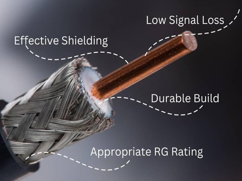
When people search “coaxial cable specifications,” they usually want a simple answer—Which cable should I buy? But in real projects, coax specs decide something more important: whether your signal stays clean, whether your assembly fits, and whether your product passes compliance without surprises. A coax cable that “looks right” can still be wrong inside—wrong impedance, the wrong shielding coverage, or a jacket that cracks after heat and oil exposure.
At Sino-Conn, we often see three starting points from customers: a part number, a short requirement list, or just a photo. The photo cases are common with traders and distributors. Engineers usually send clearer parameters, sometimes drawings. OEM factories focus on price, lead time, and stable production. If these different expectations are not aligned early, the project slows down—re-quoting, re-sampling, and re-confirming.
Coaxial cable specifications are the measurable definitions of a coax cable’s electrical performance, structure, and environmental limits. They include impedance, attenuation, shielding type and coverage, conductor and dielectric materials, outer diameter, bend radius, voltage rating, and compliance needs (UL, RoHS, REACH, etc.). Good specifications prevent signal loss, EMI problems, and assembly mismatch before production starts.
Here’s the truth: most delays don’t happen in manufacturing—they happen in the “spec gap” between what a customer imagines and what a factory can build. Close that gap, and everything gets faster.
What Are Coaxial Cable Specifications?
Coaxial cable specifications are the complete set of parameters that define how a coax cable performs and how it is built. They cover electrical targets (impedance, loss), mechanical limits (OD, bend radius), shielding structure (foil/braid), materials, and environmental/compliance needs. A complete spec allows a supplier to quote accurately, draw correctly, and produce consistently without guesswork.

What do coaxial cable specifications include?
If you want a coax cable that behaves predictably in mass production, the specs must cover electrical + mechanical + materials + compliance—not just one line like “50 ohm coax.”
Below is the practical checklist we use when customers ask for a spec sheet (cable + connector), especially when the customer only sends a photo or model number:
Core specification blocks (what customers usually care about most):
- Impedance: 50Ω / 75Ω (and tolerance)
- Frequency range / use case: RF, video, GPS, Wi-Fi, antenna, test cable
- Attenuation: loss per meter at key frequencies
- Shielding: foil, braid, double braid; coverage %
- Outer diameter (OD): affects routing + connector fit
- Bend radius / flexibility: static or dynamic movement
- Temperature rating: normal vs high-temp (e.g., 105°C / 200°C class)
- Jacket properties: flame resistance, oil resistance, UV resistance, corrosion resistance
- Compliance: UL, RoHS, REACH, PFAS requirements, halogen-free/no-fluorine needs
What’s often missing in customer inquiries (and causes mistakes):
- exact OD tolerance and connector interface
- shielding coverage (people say “shielded” but don’t say how)
- whether the cable must survive repeated bending (dynamic)
- whether “no halogen” or “no fluorine” is required (important for some markets)
Specification checklist
| Spec Item | What You Provide | What Sino-Conn Can Confirm |
|---|---|---|
| Cable model or photo | Part number / picture | Reverse check structure + OD |
| Impedance | 50Ω / 75Ω | Match cable + connector design |
| Attenuation targets | frequency points | Recommend construction options |
| Shielding | foil/braid coverage | Offer EMI-focused structures |
| OD | max OD allowed | Ensure connector compatibility |
| Bend requirement | static/dynamic | Suggest jacket + strand type |
| Environment | temp/oil/UV/fire | Material recommendation |
| Compliance | UL/RoHS/REACH/PFAS | Document set planning |
Why are coaxial cable specifications important?
Because coax problems rarely show up as “broken.” They show up as unstable performance—and that’s the worst kind of problem to debug.
Here are the failure patterns we see most often when specifications are incomplete or loosely defined:
1) Signal issues that appear only after installation
- attenuation too high at real operating frequency
- impedance mismatch causing reflections (especially in RF)
- intermittent noise because shielding coverage is too low

2) Assembly issues that waste time on the production line
- OD slightly larger than expected → connector doesn’t fit
- jacket hardness too high → routing and bending become difficult
- bend radius not suitable → cable kinks, inner dielectric deforms
3) Compliance surprises
- material not acceptable for halogen-free requirement
- flame rating or UL style needed but not specified early
- PFAS concerns in certain materials or applications
What customers gain from clear specs:
- faster quotation (less back-and-forth)
- faster drawing turnaround (we can convert CAD to PDF quickly and accurately)
- fewer samples and fewer revisions
- stable mass production lots
Where Sino-Conn fits in:
If you only have a photo or a model number, we can still move forward—by rebuilding a manufacturable specification, issuing drawings for approval, and then producing after confirmation. That process is often the difference between a smooth project and weeks of rework.
Coaxial cable specification elements
| Category | Example | What It Controls |
|---|---|---|
| Impedance | 50Ω ±2Ω | matching, reflection risk |
| Attenuation | dB/m at 1GHz, 3GHz | signal reach and stability |
| Shielding | foil + braid, 85–95% | EMI noise rejection |
| OD | 2.2 / 2.8 / 5.0 mm | routing and connector fit |
| Bend radius | 10×OD / 6×OD | kink risk, dynamic life |
| Temperature | -40 to 105°C | reliability in heat/cold |
| Jacket feature | oil/UV/flame resistant | long-term durability |
| Compliance | UL, RoHS, REACH, PFAS | market access, approvals |
Which Electrical Coaxial Cable Specifications Matter Most?
The most important electrical coaxial cable specifications are impedance accuracy, attenuation across working frequencies, voltage rating, and electrical stability over temperature. These parameters decide whether a cable delivers clean signals in real conditions, not just in lab tests. If any one of them is unclear or mismatched, performance problems usually appear after installation.
Which impedance values define coaxial cable specifications?
Most customers know they need 50 ohm or 75 ohm, but that knowledge alone is not enough.
What actually matters is:
- nominal impedance
- impedance tolerance
- impedance stability along the full cable length
Typical use cases:
- 50Ω → RF, antennas, GPS, Wi-Fi, telecom, test systems
- 75Ω → video, CCTV, broadcast, imaging

Here is the key point many customers miss:
Two cables both labeled “50Ω” can behave very differently if one has loose tolerance or inconsistent dielectric control.
Why impedance drifts in real production
- uneven dielectric thickness
- center conductor not perfectly concentric
- inconsistent extrusion speed
These issues do not always show up in short samples but appear in longer assemblies or mass production.
What Sino-Conn checks when impedance matters
- whether the application is sensitive to reflections
- whether tighter impedance control is needed or not
- whether the original design is over-specified (cost can sometimes be reduced safely)
Practical advice
If your cable connects to RF modules, antennas, or test equipment, impedance tolerance matters more than brand or appearance.
How does attenuation affect coaxial cable specifications?
Attenuation is where many sourcing decisions quietly fail.
Attenuation is not:
- a single number
- independent of frequency
- irrelevant for short cables
Attenuation is always:
- frequency-dependent
- affected by conductor material and surface quality
- cumulative over length
Example of how loss increases with frequency:
| Frequency | Typical Loss Trend |
|---|---|
| 100 MHz | Low |
| 1 GHz | Moderate |
| 3 GHz | High |
| 6 GHz+ | Very high |
Common real-world mistake
A cable works in testing but fails in the final product because:
- the frequency increased
- the cable length increased
- routing introduced tighter bends
Attenuation rises faster than most people expect.
At Sino-Conn, we often re-evaluate attenuation based on:
- actual operating frequency
- real cable length
- routing environment
This avoids a common situation where a cable “meets the datasheet” but fails in use.
How do voltage ratings influence coaxial cable specifications?
Many customers underestimate voltage requirements because coaxial cables are often seen as “signal only.”
In reality, voltage rating still matters because:
- insulation stress increases with temperature
- spikes can occur during power-up or discharge
- compact designs reduce safety margin
Typical voltage ranges:
- 300–600V → standard signal applications
- 600–1000V → industrial or higher safety margin
- 1000V+ → special test or harsh environments
Voltage rating depends mainly on:
- dielectric material (PE vs FEP vs PTFE)
- insulation thickness
- manufacturing consistency
Cost reality
Higher voltage rating usually means:
- thicker insulation
- higher material cost
- larger OD
Sino-Conn often helps customers confirm whether the original voltage rating is truly required or simply inherited from an older design.
How does temperature affect electrical coaxial cable specifications?
Electrical performance does not stay constant as temperature changes.
As temperature increases:
- dielectric loss increases
- attenuation rises
- impedance stability can shift
Common temperature classes:
- –20°C to +80°C → indoor electronics
- –40°C to +105°C → industrial / automotive
- –55°C to +200°C → high-temperature environments
Typical hidden issue
A cable passes electrical tests at room temperature but shows higher loss or instability after long-term heat exposure.
This is why Sino-Conn always asks:
- continuous operating temperature
- peak exposure temperature
- whether heat is constant or intermittent
Temperature is not just an environmental spec—it directly affects electrical behavior.
Which electrical specs are often misunderstood or ignored?
Some electrical specifications cause problems simply because customers don’t realize they matter.
Commonly overlooked items:
- impedance tolerance (not just nominal value)
- attenuation change after bending
- electrical stability over long cable runs
- interaction between cable and connector
Example scenario
A customer replaces a cable with a “same-looking” version:
- impedance listed the same
- OD looks similar
- connector fits
But EMI issues appear because attenuation and shielding effectiveness differ slightly.
Electrical specs must always be considered as a system, not as isolated numbers.
Electrical coaxial cable specifications that affect real performance
| Spec | What It Controls | Why Customers Care |
|---|---|---|
| Impedance | Signal matching | RF stability |
| Impedance tolerance | Reflection risk | Performance consistency |
| Attenuation | Signal strength | Max usable length |
| Voltage rating | Safety margin | Reliability |
| Temp stability | Loss drift | Long-term performance |
How Do Physical Coaxial Cable Specifications Affect Use?
Physical coaxial cable specifications determine whether a cable can be installed, routed, bent, and assembled without damage. Outer diameter, bend radius, flexibility, and material hardness directly affect connector fit, assembly yield, and long-term reliability. Ignoring physical specs often leads to installation failures rather than electrical faults.
How does OD impact coaxial cable specifications?
Outer diameter (OD) seems simple, but it affects more decisions than almost any other spec.
OD directly influences:
- connector compatibility
- routing through housings or panels
- weight and stiffness
- bundle density
A difference of 0.2–0.3 mm can:
- prevent a connector from crimping correctly
- cause interference in tight assemblies
- increase stress at bend points
When customers send photos only, OD is often unknown. Sino-Conn typically:
- measures reference samples
- estimates OD from connector interface
- confirms maximum allowable OD before finalizing structure
Important reality:
Reducing OD often increases cost because it requires tighter tolerances and thinner dielectric layers. OD is not just a cosmetic choice—it’s a structural one.

How does flexibility relate to coaxial cable specifications?
Flexibility is not a single parameter. It depends on:
- conductor strand count
- dielectric hardness
- jacket material and thickness
Two cables with the same OD can behave very differently.
Use cases:
- Static installation: routing once, no repeated movement
- Dynamic installation: repeated bending, vibration, or motion
Dynamic applications require:
- finer conductor stranding
- softer jacket materials
- larger bend radius margin
Common sourcing mistake:
Customers request “soft cable” without defining whether the cable will move during use. Sino-Conn always asks this question because dynamic use changes the internal structure significantly.
Which materials are used in coaxial cable specifications?
Material selection defines durability, flexibility, and compliance.
Common choices:
- Conductor: bare copper, tinned copper, silver-plated copper
- Dielectric: PE (cost-effective), FEP (heat resistant), PTFE (high performance)
- Jacket: PVC, PU, FEP, LSZH

Material decisions affect:
- temperature range
- chemical resistance
- flame behavior
- regulatory acceptance
Market differences we see:
- US & EU: higher demand for flame retardant and compliance
- Japan: strong focus on consistency and material stability
- OEM factories: cost-sensitive but volume-driven
Sino-Conn typically provides two or more material options—one optimized for performance, one optimized for cost—so customers can choose based on real priorities.
Physical coaxial cable specification considerations
| Spec | Low Impact | High Impact |
|---|---|---|
| OD | loose routing | tight connectors |
| Bend radius | static use | dynamic motion |
| Jacket hardness | fixed install | vibration |
| Material choice | indoor use | harsh environment |
What Shielding and EMI Coaxial Cable Specifications Are Used?
Shielding and EMI coaxial cable specifications define how effectively a cable blocks external noise and prevents signal leakage. These specifications include shielding structure, coverage density, grounding continuity, and termination quality. Correct EMI specs are critical in RF, medical, industrial, and test systems where unstable signals cannot be corrected after installation.
What shielding structures are used in coaxial cable specifications?
In real sourcing conversations, “shielded coax” is not a specification—it is only a starting point. What actually matters is how the shield is built and how dense it is.
The most common shielding structures used in coaxial cable specifications are:
- Single braided shield One layer of copper or tinned copper braid. Typical coverage: 70–85% Used in low-noise or cost-sensitive applications where EMI exposure is limited.
- Foil + braid Aluminum or copper foil combined with a braided layer. Typical coverage: 90–95% This is the most common structure for RF, antennas, GPS, and data signal cables.
- Double braided shield Two braided layers without foil. Typical coverage: 90–95%, with higher mechanical strength. Often used where vibration or repeated bending is expected.
- Foil + double braid The highest EMI protection level used in standard coaxial assemblies. Coverage often exceeds 95%. Common in medical equipment, industrial control systems, and sensitive test instruments.
What customers often miss:
Two cables with the same outer diameter and same connector can have completely different EMI behavior simply because braid density differs. This difference is invisible in photos and only appears during operation.
How does shielding coverage affect EMI performance?
Shielding coverage percentage is one of the few EMI parameters that can be quantified and compared, yet many buyers never ask for it.
Typical coverage ranges and what they mean:
| Shield Coverage | EMI Resistance | Practical Result |
|---|---|---|
| 70–75% | Low | Signal easily affected by nearby noise |
| 80–85% | Medium | Acceptable for basic electronics |
| 90–95% | High | Stable RF and data performance |
| >95% | Very High | Required for medical / test systems |
Higher coverage:
- reduces electromagnetic leakage
- stabilizes signal amplitude
- improves consistency across production batches
Trade-off reality:
Higher coverage usually means:
- thicker braid
- slightly higher stiffness
- higher material cost
At Sino-Conn, we often offer two shielding options during quotation:
- One optimized for cost
- One optimized for EMI stability
This allows customers to make a decision based on actual risk, not assumptions.
How do grounding and termination affect EMI specifications?
Many EMI failures are not caused by the cable itself—but by how the shield is terminated.
Even a well-designed shield can fail if:
- the braid is damaged during stripping
- foil is not bonded correctly
- connector shell does not make full 360° contact
Key termination factors that affect EMI:
- consistency of braid contact with connector body
- crimp height and compression force
- solder vs crimp method selection
- alignment between cable OD and connector internal dimensions
Common field issue:
Customers test a sample cable and approve it, but EMI performance changes in mass production. In most cases, the root cause is termination variation, not cable structure.
Sino-Conn controls this by:
- matching cable OD tightly to connector design
- using defined termination work instructions
- inspecting shielding continuity during process checks
This is why cable and connector should always be specified as a complete assembly, not as separate parts.
Which applications require stricter EMI coaxial cable specifications?
Not every application needs the highest EMI shielding—but some absolutely do.
Applications that typically require 90%+ shielding coverage:
- RF antennas and communication modules
- GPS and GNSS systems
- medical imaging and monitoring equipment
- industrial sensors near motors or power lines
- automated test and measurement systems

Applications that may accept lower shielding levels:
- short internal connections
- consumer electronics with low noise exposure
- fixed installations away from EMI sources
Sourcing mistake we often see:
Customers copy shielding specs from a previous project without considering whether the environment changed. EMI requirements should be tied to where the cable is used, not just what it connects.
EMI-related coaxial cable specification checklist
| Item | Why It Matters |
|---|---|
| Shield type | Determines base EMI resistance |
| Coverage % | Predicts noise suppression level |
| Braid material | Affects durability and grounding |
| Foil overlap | Prevents high-frequency leakage |
| Termination method | Controls real-world EMI outcome |
| Connector fit | Ensures full shield continuity |
What Environmental Coaxial Cable Specifications Are Required?
Environmental coaxial cable specifications define where and how a cable can safely operate. These include temperature range, flame resistance, oil and UV resistance, corrosion protection, and material compliance. Environmental specs are critical for passing certification, surviving real conditions, and avoiding early failure in long-term use.
What temperature ratings belong to coaxial cable specifications?
Temperature rating is one of the first specs engineers check—and one of the first specs traders overlook.
Common temperature classes include:
- –20°C to +80°C: indoor commercial use
- –40°C to +105°C: industrial and automotive
- –55°C to +200°C: high-temperature or PTFE-based designs
Temperature affects:
- dielectric stability
- jacket aging
- attenuation drift over time
Real-world issue:
A cable may pass initial testing but fail after months if the jacket hardens or the dielectric deforms under heat.
Sino-Conn always confirms:
- continuous operating temperature
- peak exposure temperature
- whether heat comes from environment or nearby components
What fire and chemical specs appear in coaxial cable specifications?
Fire and chemical resistance are often market-specific.
Common requirements include:
- flame retardant jackets
- oil resistance (industrial machinery)
- UV resistance (outdoor routing)
- corrosion resistance (humid or chemical environments)
Material choices play a big role:
- PVC: cost-effective, limited heat resistance
- PU: better abrasion and oil resistance
- FEP / PTFE: excellent heat and chemical stability
- LSZH: low smoke, halogen-free environments
Important note:
“Halogen-free” and “no fluorine” are not the same thing. Some markets care deeply about this distinction, and Sino-Conn confirms it early to avoid compliance issues later.
Which certifications support coaxial cable specifications?
Certification requirements vary by country and industry.
Commonly requested documents:
- UL
- RoHS
- REACH
- PFAS statements
- COC / COO
Sino-Conn prepares documentation in parallel with production, not after. This avoids shipment delays and repeated audits.
Environmental specification focus by market
| Market | Key Focus |
|---|---|
| United States | UL, flame resistance |
| Europe | RoHS, REACH, chemical control |
| Japan | material stability, consistency |
| Medical | high EMI + documentation |
| Military | durability, traceability |
How Can Coaxial Cable Specifications Be Customized?
Most coaxial cable specifications can be customized, including length, connector type, pin-out, materials, shielding level, and compliance targets. Customization works best when specifications are confirmed with drawings before production, ensuring the final cable matches both performance and assembly requirements.
Which parts of coaxial cable specifications can be customized?
At Sino-Conn, nearly every project involves customization.
Common adjustable elements:
- cable length (no MOQ, 1 piece accepted)
- connector type (original or alternative)
- pin-out and interconnection logic
- cable material and structure
- shielding level
- labeling and marking
Customers often ask whether original connectors are required.
Reality:
- original connectors cost more and have longer lead times
- alternatives offer similar performance, faster delivery, and flexibility
We explain both options clearly so customers can choose based on budget, schedule, and application, not guesswork.
How are coaxial cable specifications confirmed before production?
Specification confirmation is where many suppliers slow down. Sino-Conn treats it as a speed advantage.
Our workflow:
- clarify missing parameters
- prepare drawings (CAD → PDF)
- send for customer confirmation
- begin production only after approval
Typical timing:
- drawings in 30 minutes to 3 days
- samples in as fast as 3 days
- mass production in 2–4 weeks

Every order follows this process—no exceptions.
Request Custom Coaxial Cable Specifications from Sino-Conn
If you already have a model number, drawing, or datasheet—send it.
If you only have a photo—send it.
If you only know the application—send that.
Sino-Conn helps customers turn unclear ideas into clear coaxial cable specifications, confirmed by drawings and supported by fast sampling, flexible customization, and full inspection.
- No MOQ (1 piece accepted)
- Fast drawings and quotations
- Original or alternative connectors
- Full documentation support
- 100% inspection before shipment
Contact Sino-Conn today to discuss your coaxial cable specifications and start a custom solution built for your real application—not assumptions.


